manuals.online logo
Brands
  1. Home
  2. •
  3. Brands
  4. •
  5. Flowserve
  6. •
  7. Control Unit
  8. •
  9. Flowserve Valtek CavControl Trim Guide

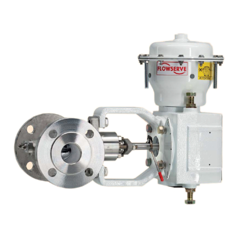
Flowserve Valtek CavControl Trim Guide

Valtek No. 10003460 15-1
Flowserve Corporation, Valtek Control Products, Tel. USA 801 489 8611
Valtek CavControl Trim
GENERAL INFORMATION
The following instructions are designed to assist in
assembling, disassembling and troubleshooting
Valtek® globe valves equipped with CavControl™ trim.
Product users should thoroughly review this bulletin in
conjunction with Installation, Operation, Maintenance
Instruction 1 (Mark One and Mark Two Control Valves)
and Installation, Operation, Maintenance Instruction 24
(Valtek Beta Positioner) before installing, operating or
performing any maintenance on the valve.
To avoid possible injury to personnel or dam-
age to valve parts, WARNING and CAUTION
notes must be strictly followed. Modifying this
product, substituting non-factory or inferior
parts, or using maintenance procedures other
than outlined could drastically affect perfor-
mance and be hazardous to personnel and
equipment.
Installation
Standard unpacking and installation instructions are
outlined in Installation, Operation, Maintenance Instruc-
tion 1. Regardless of the air-action, valves equipped
with CavControl trim must be installed in the line with the
flow direction over the plug.
CAUTION: Improper installation will result in severe
cavitation damage to the valve.
NOTE: Flowserve recommends a strainer be installed
upstream of the valve prior to start-up. This will help
prevent debris build-up and trim fouling.
DISASSEMBLY AND REASSEMBLY
Disassembling CavControl Trim
When disassembling valves with CavControl trim, refer
to either figure 1 or 2 and proceed as follows:
WARNING: Depressurize line to atmospheric pres-
sure or remove valve from line and drain all process
fluids and decontaminate the valve (if caustic or
hazardous materials are present). Failure to follow
this warning can cause serious injury.
1. Stroke the valve to the full open position by applying
air to the lower cylinder port.
2. Remove the bonnet flange bolting and lift the ac-
tuator/plug assembly out of the valve body.
CAUTION: Lift the actuator/plug assembly
straight out of the valve body to avoid damage
to the plug head, seat ring or trim. If the actuator
is not provided with a lifting ring, use lifting
straps around the yoke legs.
WARNING: With pressure-balanced trim,
danger exists in removing the actuator/plug
assembly out of the valve body, especially if
PTFE pressure seals are used on the plug. The
pressure-balanced sleeve could bind on the
plug, allowing the sleeve to be lifted out of the
body along with the actuator/plug assembly. If
the sleeve should loosen and fall, it could cause
personal injury and damage valve parts or
nearby equipment. Step 3 outlines the correct
procedure for removing the sleeve from the
plug.
15-2 Flowserve Corporation, Valtek Control Products, Tel. USA 801 489 8611
3. If the pressure-balanced sleeve binds with the plug,
carefully lift the sleeve out with the actuator/plug
assembly. Place several sturdy, soft supports (pref-
erably wood) underneath the sleeve after it clears
the body. Lower the actuator/plug assembly until
the sleeve and the supports are resting on top of the
body.
NOTE: The above procedure is designed to prevent
damage to the body should the sleeve fall during
disassembly.
To free the sleeve from the plug, apply air above the
actuator piston, extending the plug. This creates a
gap between the bonnet and sleeve. Insert wood
blocks of equal thickness in at least three positions
in this gap. Blocks should be at least 1-inch thick and
should be positioned so as to not interfere with the
plug head. Finally, retract the plug until the sleeve is
free of the plug.
4. If the sleeve has not been removed with the plug, lift
it out of the valve body.
5. Remove the seat ring and gaskets from the valve
body.
6. If the plug is pressure-balanced, remove the plug
seals.
7. If necessary, the plug may be removed from the
actuator and bonnet in accordance with the basic
valve instructions.
Reassembling CavControl Trim
When reassembling valves with CavControl trim, refer
to either Figure 1 or 2 and proceed as follows:
1. Install new bonnet and seat ring gaskets.
2. Reinstall seat ring and sleeve.
3. For pressure-balanced trim, install a new sleeve
gasket on sleeve and new plug seals on plug head.
Figure 1: Unbalanced CavControl Trim
NOTE: Item numbers correspond directly to the item numbers on the bill of material; refer to it for specific part numbers.
Bonnet Flange Bolting
(Item No. 108/114)
Bonnet Gasket
(Item No. 58)
Sleeve
(Item No. 30)
Seat Ring
(Item No. 20)
Seat Gasket
(Item No. 55)
Body
(Item No. 1)
Bonnet
(Item No. 40)
Bonnet Flange
(Item No. 70)
Plug
(Item No. 50)
Flowserve Corporation, Valtek Control Products, Tel. USA 801 489 8611 15-3
4. Retract plug to the full-open position by applying air
to the lower cylinder port.
5. Lower the actuator/plug assembly squarely into
the valve body.
CAUTION: Lower plug squarely into sleeve to
prevent galling and scoring of trim parts. Plug
seals must be compressed, using an appropri-
ate ring compressor, until they enter the
pressure-balanced sleeve. Stagger the cuts on
the PTFE seals or the gaps on the piston ring
seals 180O(for 2 rings) or 120O(for 3 rings) to
minimize leakage.
6. Hand-tighten the bonnet flange bolting.
7. For pressure-balanced trim with PTFE seals, drive
the plug into the sleeve by applying air to the
actuator until the plug seats. Repeat operation, if
necessary, to bring the bonnet fully down into the
body.
8. Stroke the valve two or three times to ensure that
the plug and seat ring are concentrically aligned for
proper seating.
9. Apply air pressure above the actuator piston (or to
the top port) to seat the plug. This ensures that the
plug and seat ring remain concentrically aligned
during the tightening of the bonnet flange bolting.
Tighten two opposing bonnet flange bolts or nuts
1/6of a turn (one flat). Tighten all bolting in this
manner evenly and completely. Proper bonnet
gasket compression occurs when the bonnet is
seated metal-to-metal in the body. This requires
considerable force; however, the bottoming of the
bonnet metal-to-metal in the body can easily be felt
through the wrench.
CAUTION: Insufficient tightening will result in
improper seat ring gasket compression.
10. If the valve has been removed from the line, make
sure flow direction is correct upon reinstallation.
Figure 2: Pressure-balanced CavControl Trim
NOTE: Item numbers correspond directly to the item numbers on the bill of material; refer to it for specific part numbers.
Bonnet Flange Bolting
(Item No. 108/114)
Sleeve Gasket
(Item No. 56)
Bonnet Gasket
(Item No. 58)
Seat Ring
(Item No. 20)
Seat Gasket
(Item No. 55)
Body
(Item No. 1)
Plug Seal
(Item No. 65)
Pressure-balancing
Vent
Bonnet
(Item No. 40)
Bonnet Flange
(Item No. 70)
Pressure-balanced Sleeve
(Item No. 30)
Plug
(Item No. 50)
© 2000 Flowserve Corporation. Flowserve Corporation, Valtek Control Products, Tel. USA 801 489 8611
FCD VLAIM015-07
Troubleshooting Chart
Failure Probable Cause Corrective Action
Jerky stem 1. Overtightened graphite packing 1. Graphite packing is often associated with jerky
movement stem movement
2. Galling or scoring between plug 2. Superficial scoring or galling may be removed
andsleeve with a light application of emery cloth; if more
serious damage exists, contact factory
CAUTION: Trim parts are machined to close
tolerances, which are essential for correct
functioning of the valve. Attempting to remove
deep scratches could result in high leakage
rates or improper functioning of the valve
3. Overtightened packing 3. Adjust the packing box nuts to just slightly over
finger-tight (over-tightening will also cause
excessive packing wear and high stem friction)
4. Service temperature is beyond 4. Reconfirm service conditions and contact factory
operating parameter of trim design
5. Inadequate air supply 5. Check for leaks in air supply or instrument
signal system; tighten any loose connections
and replace any leaking lines
6. Malfunctioning positioner 6. Refer to positioner maintenance instruction
Excessive 1. Loose bonnet flange bolting 1. Refer to step 9 of “Reassembly”section for
leakage correct tightening procedure
2. Worn or damaged seat ring 2. Disassemble and replace or repair seat ring
(for correct procedure on remachining seat
surfaces, see Maintenance Instruction 1)
3. Worn or damaged pressure- 3. Disassemble and replace plug seals
balanced plug seals
4. Worn or damaged seat, 4. Disassemble and replace gaskets
bonnet or sleeve gaskets
5. Inadequate actuator thrust 5. Check for adequate air supply to the actuator; if
supply is OK, reconfirm service conditions and
contact factory
6. Incorrectly adjusted plug 6. Refer to Installation, Operation, Maintenance,
Instruction 1 for correct plug adjustment
7. Improper flow direction 7. Confirm flow direction is always over the plug
Excessive 1. Worn or damaged plug seals 1. Disassemble and replace plug seals
cavitation causing excessive trim vibration
damage 2. Misapplication of trim design 2. Reconfirm service conditions and contact factory
3. Improper flow direction 3. Reinstall with flow direction over the plug
4. Severe corrosive service 4. Reconfirm service conditions and contact factory
exceeds trim material limitations
Inadequate 1. Improper plug adjustment 1. Refer to Installation, Operation, Maintenance
flow limiting stroke Instruction 1 for correct plug adjustment
2. Malfunctioning positioner 2. Refer to positioner maintenance instruction
3. Blocked pressure-balanced plug 3. Eliminate matter from line, disassemble and
vents or sleeve holes clean plug vents and sleeve
4. Service conditions exceeding 4. Verify service conditions and consult factory
trim design capacity
Plugslams 1. Incorrect plug adjustment allowing 1. Refer to Maintenance Instruction 1 for correct
improper cushion of air between plug adjustment
actuator piston and yoke
2. Inadequate air supply 2. Check air supply to actuator; repair leaks and
remove any restrictions in the supply line
3. Trim sized too large for flow rate 3. Install reduced trim to provide greater plug-to-seat
clearance

Other Flowserve Control Unit manuals

Flowserve AKH2A User manual

Flowserve

Flowserve AKH2A User manual

Flowserve AKH6 User manual

Flowserve

Flowserve AKH6 User manual

Flowserve AKH2 User manual

Flowserve

Flowserve AKH2 User manual

Flowserve NAF ProCap Installation instructions

Flowserve

Flowserve NAF ProCap Installation instructions

Flowserve Valtek Three-way Guide

Flowserve

Flowserve Valtek Three-way Guide

Flowserve Durco Sleeveline G4XZ User manual

Flowserve

Flowserve Durco Sleeveline G4XZ User manual

Flowserve 818 Series Manual

Flowserve

Flowserve 818 Series Manual

Flowserve 94 Series Manual

Flowserve

Flowserve 94 Series Manual

Flowserve McCANNA User manual

Flowserve

Flowserve McCANNA User manual

Flowserve CPT 44 Manual

Flowserve

Flowserve CPT 44 Manual

Flowserve MASTER STATION IV EEP-SN4001 User manual

Flowserve

Flowserve MASTER STATION IV EEP-SN4001 User manual

Flowserve Valtek GS User manual

Flowserve

Flowserve Valtek GS User manual

Flowserve FlowTop V726 Installation instructions

Flowserve

Flowserve FlowTop V726 Installation instructions

Flowserve Series 081000 User manual

Flowserve

Flowserve Series 081000 User manual

Flowserve Valtek Tek-Check Guide

Flowserve

Flowserve Valtek Tek-Check Guide

Flowserve Valtek Mark 100 User manual

Flowserve

Flowserve Valtek Mark 100 User manual

Flowserve ARL User manual

Flowserve

Flowserve ARL User manual

Flowserve atomac ARV/SG Series User manual

Flowserve

Flowserve atomac ARV/SG Series User manual

Flowserve Valtek MaxFlo 3 Owner's manual

Flowserve

Flowserve Valtek MaxFlo 3 Owner's manual

Flowserve GESTRA BB 1 Series User manual

Flowserve

Flowserve GESTRA BB 1 Series User manual

Flowserve Edward 602Y User manual

Flowserve

Flowserve Edward 602Y User manual

Flowserve NAF-Setball User manual

Flowserve

Flowserve NAF-Setball User manual

Flowserve ASG 3 User manual

Flowserve

Flowserve ASG 3 User manual

Flowserve T4E-1 User manual

Flowserve

Flowserve T4E-1 User manual

Popular Control Unit manuals by other brands

Stone STWC050LT-01 Equipment manual

Stone

Stone STWC050LT-01 Equipment manual

Trane Tracer MP503 Installation, operation and maintenance

Trane

Trane Tracer MP503 Installation, operation and maintenance

Tigo TS4-A-2F Installation & quick start guide

Tigo

Tigo TS4-A-2F Installation & quick start guide

Smartgen CMM366B-4G user manual

Smartgen

Smartgen CMM366B-4G user manual

GGM GUD Series Operation manual

GGM

GGM GUD Series Operation manual

Tektronix MultiPaq VX4101A user manual

Tektronix

Tektronix MultiPaq VX4101A user manual

Linear 300 Series quick start guide

Linear

Linear 300 Series quick start guide

Intertronic IDMHDV-130 user manual

Intertronic

Intertronic IDMHDV-130 user manual

Kemper Protect BA Figure 366 Installation instruction

Kemper

Kemper Protect BA Figure 366 Installation instruction

Crestron FT2A-PWR-UK-1-C14 installation guide

Crestron

Crestron FT2A-PWR-UK-1-C14 installation guide

Balcrank Synergy 3110-019 Service bulletin

Balcrank

Balcrank Synergy 3110-019 Service bulletin

Assa Abloy Securitron B100 quick start guide

Assa Abloy

Assa Abloy Securitron B100 quick start guide

CM RIESE SAFE X4 Original operating instructions

CM

CM RIESE SAFE X4 Original operating instructions

BrassCraft 2000 installation instructions

BrassCraft

BrassCraft 2000 installation instructions

Cistermiser IRC installation guide

Cistermiser

Cistermiser IRC installation guide

Congatec SMARC conga-SMX8-X user guide

Congatec

Congatec SMARC conga-SMX8-X user guide

IRIS IRIS-RS232 Short manual

IRIS

IRIS IRIS-RS232 Short manual

Ingersoll-Rand Sierra Series General information

Ingersoll-Rand

Ingersoll-Rand Sierra Series General information

manuals.online logo
manuals.online logoBrands
  • About & Mission
  • Contact us
  • Privacy Policy
  • Terms and Conditions

Copyright 2025 Manuals.Online. All Rights Reserved.