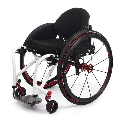
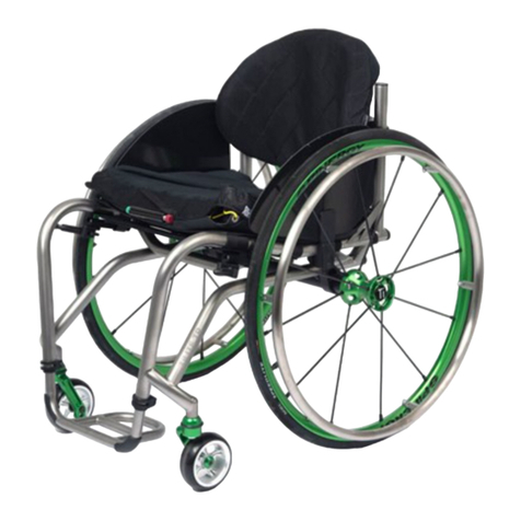
TiLite ZR User manual

DLC:GHB6CJ6AHJEEA:B:CI
SERIES 2
SERIAL NUMBER ______________________
SERIES 2
Z2SUPP_0211Rev B

Z2SUPP_0211RevB Z Series 2_Supplement
i
I WARNING - READ THIS MANUAL
DO NOT OPERATE THIS WHEELCHAIR WITHOUT FIRST READING AND UNDERSTANDING THIS TiLITE
OWNERS MANUAL SUPPLEMENT. IF YOU ARE UNABLE TO UNDERSTAND THE WARNINGS, CAUTIONS
AND INSTRUCTIONS, CONTACT YOUR TiLITE DEALER OR TiLITE CUSTOMER SUPPORT AT (800) 545-2266
BEFORE ATTEMPTING TO USE THIS WHEELCHAIR.
IF YOU IGNORE THIS WARNING, YOU MAY FALL, TIP
OVER OR LOSE CONTROL OF THE WHEELCHAIR AND SERIOUSLY INJURE YOURSELF OR OTHERS OR
DAMAGE THE WHEELCHAIR.
IWARNING - READ TiLITE AERO Z, ZR AND ZRA OWNERS MANUAL
THIS TiLITE OWNERS MANUAL SUPPLEMENT IS INTENDED TO SUPPLEMENT THE TiLITE AERO Z, ZR AND
ZRA OWNERS MANUAL. PLEASE READ ALL WARNINGS CONTAINED IN THE AERO Z, ZR AND ZRA OWNERS
MANUAL BEFORE USING THE TiLITE ZR SERIES 2, ZRA SERIES 2 AND AERO Z SERIES 2.
IF YOU IGNORE
THIS WARNING, YOU MAY FALL, TIP OVER OR LOSE CONTROL OF THE WHEELCHAIR AND SERIOUSLY
INJURE YOURSELF OR OTHERS AND DAMAGE THE WHEELCHAIR.

Z Series 2_Supplement Z2SUPP_0211RevB
ii
CONTENTS
CHAPTER 1: BACKRESTS 1-1
FOLDING ADJUSTABLE HEIGHT AND ANGLE BACKREST (Titanium or Aluminum) 1-1
Folding the Backrest 1-1
Unfolding the Backrest 1-1
Unfolding the Lock-Down Backrest 1-1
Adjusting the Backrest Mount 1-1
Changing the Backrest Angle 1-2
Adjusting the Backrest Height 1-3
Replacing the Backrest 1-4
FOLDING ADJUSTABLE DEPTH, HEIGHT & ANGLE BACKREST (Titanium or Aluminum)
(Aero Z Series 2 and ZRA Series 2) 1-5
Adjusting the Depth 1-5
CHAPTER 2: ARMRESTS 2-1
ANGLE ADJUSTABLE SWING AWAY AND SWING AWAY-FLIP BACK ARMREST 2-1
SWING AWAY ARMREST 2-1
Adjusting the Angle 2-1
Adjusting the Height of the Swing Away Armrest 2-2
SWING AWAY-FLIP BACK ARMREST 2-2
Adjusting the Armrest Height 2-3
Adjusting the Armrest Angle 2-3
CHAPTER 3: SIDE GUARDS 3-1
ADJUSTABLE FENDERED SIDE GUARD (Aluminum) 3-1
Mounting 3-1
Adjusting 3-2
CHAPTER 4: AXLE PLATES AND CAMBER TUBES (CENTER OF GRAVITY;
REAR SEAT HEIGHT) 4-1
Adjusting the Center of Gravity (ZR Series 2) 4-1
Replacing the Camber Tube (ZR Series 2) 4-2
Adjusting the Rear Seat Height (Aero Z Series 2 and ZRA Series 2) 4-2
Adjusting the Center of Gravity (Aero Z Series 2 and ZRA Series 2) 4-3
Replacing the Camber Tube (Aero Z Series 2 and ZRA Series 2) 4-4
CHAPTER 5: CASTERS WITH STANDARD FORKS 5-1
Replacing Casters 5-1
Replacing Forks 5-2
CASTERS WITH MONO FORKS 5-2
Replacing Casters 5-2
Replacing Forks 5-3
ANGLE ADJUSTABLE SPEEDLOADER CASTER MOUNT (Aero Z Series 2 and ZRA Series 2) 5-4
Adjusting the Angle 5-4
CHAPTER 6: ACCESSORIES 6-1
REAR ANTI-TIPS 6-1
Adjusting 6-1
Mounting (ZR Series 2) 6-1

Z2SUPP_0211RevB Z Series 2_Supplement
iii
Mounting (Aero Z Series 2 and ZRA Series 2) 6-2
USER-FRIENDLY ANTI-TIPS 6-3
Engaging 6-3
Disengaging 6-4
Adjusting 6-4
Removing 6-5
Mounting 6-5
VELCRO®-STYLE ADJUSTABLE SEAT BELT 6-7
Installation 6-7
Adjustment 6-8
Safety Check 6-8
Maintenance 6-8

1-1
Z Series 2_Supplement Z2SUPP_0211RevB
CHAPTER 1: BACKRESTS
FOLDING ADJUSTABLE HEIGHT AND ANGLE BACKREST (Titanium or Aluminum)
I WARNING
Before using your wheelchair, make sure the Folding Adjustable Height & Angle Backrest is locked securely in place
in the upright position and all mounting hardware is securely tightened.
If you ignore this Warning, you may fall, tip
over or lose control of the wheelchair and seriously injure yourself or others or damage the wheelchair.
Folding the Backrest
1. Grasp the TiShaft Release Bar and pull up. See Figure 1-1.
2. Push the backrest forward toward the front of the chair.
Note: If you have a Lock-Down backrest, make sure the backrest is locked securely in the folded position.
Unfolding the Backrest
1. Lift up on the backrest and pull towards the rear of the chair.
2. Make sure the backrest locks securely into place.
Unfolding the Lock-Down Backrest
1. Push up the TiShaft Release Bar and pull the backrest towards the rear of the chair.
2. Make sure the backrest locks securely into place.
Adjusting the Back Mount
Tools Needed:
• Two7/16”OpenEndWrenches
Ifyourbackrestisdifculttofoldandunfoldoristooloose,followtheseprocedures:
1. Using an Open End Wrench, hold the pivot bolt in place and slightly loosen or tighten the nylock nut with the
second Open End Wrench. See Figure 1-2.
2. Repeat the procedure on each side of the chair until the desired tightness is achieved.
Figure 1-1
Folding Adjustable Backrest with TiShaft Release Bar
TiShaft
Release Bar
Backrest

1-2
Z Series 2_Supplement Z2SUPP_0211RevB
CHAPTER 1: BACKRESTS
Changing the Backrest Angle
Tools Needed:
• Two1/2”OpenEndWrenches
• 1/8”AllenWrench
1. On each side of the chair, using the Allen Wrench, remove the Buttom Head Cap Screw and lock washer. See
Figure 1-3.
2. On each side of the chair, using the Open End Wrenches, loosen but do not remove the stop bolt and nylock nut.
3. Adjust the backrest to the desired angle. On one side of the chair, while holding the backrest in place, align one
oftheveholesinthebackrestcamwithoneofthethreeholesinthebackmount.PlacetheButtonHeadCap
Screw through the lock washer, the backrest cam and into the back mount. Securely tighten.
4. Securely tighten the stop bolt and nylock nut.
5. Repeat Steps 3 and 4 on the other side of the chair.
Figure 1-2
Adjusting the Backrest Mount
Pivot Bolt
Nylock Nut
Figure 1-3
Changing the Back Angle
Backrest
Backrest
Cam
Button Head Cap Screw
Stop Bolt
Back
Mount
Nylock
Nut
Lock Washer

1-3
Z Series 2_Supplement Z2SUPP_0211RevB
CHAPTER 1: BACKRESTS
Adjusting the Backrest Height
Tools Needed:
• 5/32”AllenWrench
Note: In order to adjust the backrest height, it is helpful to remove the backrest upholstery. Therefore, make a note of
the tautness of the backrest upholstery before removing it so you can reinstall it to approximately the same degree of
tautness.
1. Remove the backrest pad. See “Velcro®-StyleAdjustableBackUpholstery”or“TensionAdjustablebyStraps
BackUpholstery”onpages7-1to7-3intheAeroZ,ZRandZRAOwnersManual.
2. On both sides of the chair, remove the Allen Screw that secures the backrest post inside the backrest. See Figure
1-4.
3. Reposition both backrest posts to the desired height inside the backrest, and reinsert and securely tighten the two
Allen Screws.
4. Make sure both backrest posts are at the same height in the backrest.
5. Reinstall the backrest upholstery. See “Velcro®-StyleAdjustableBackUpholstery”or“TensionAdjustableby
StrapsBackUpholstery”onpages7-1to7-3intheAeroZ,ZRandZRAOwnersManual.
I WARNING
The threads on the Allen Screws that secure the backrest posts to the backrest have been treated with a Vibra-TITE®
VC-3, a locking and sealing coating, to reduce the possibility that they will become loose. You should be able to adjust
the backrest height approximately four times without reapplying thread lock to these screws. TiLite requires that
you reapply Vibra-TITE®VC-3 after every fourth adjustment.
If you ignore this Warning, your backrest posts could
become loose or disconnected from the wheelchair, and you could fall, tip over or lose control of the wheelchair
and seriously injure yourself or others or damage the wheelchair.
Figure 1-4
Adjusting the Backrest Height
Backrest
Backrest
Post
Allen
Screw

1-4
Z Series 2_Supplement Z2SUPP_0211RevB
CHAPTER 1: BACKRESTS
Note:Ifyourbackrestissetto8-½”andyouneedtoadjustthebackrestheightto9”to11-½”,thefollowingprocedure
applies:
1. Remove the backrest upholstery. See “Velcro®-StyleAdjustableBackUpholstery”or“TensionAdjustableby
StrapsBackUpholstery”onpages7-1to7-3intheAeroZ,ZRandZRAOwnersManual.
2. Remove the top end caps. See Figure 1-5.
3. Install the backrest sleeve in each backrest tube.
4. Align the backrest posts inside the backrest so that the desired hole in the backrest post aligns with one of the
holes in the backrest.
5. Secure the backrest posts inside the backrest using the Allen Screws. See Figure 1-6.
6. Reinstall the backrest upholstery. See “Velcro®-StyleAdjustableBackUpholstery”or“TensionAdjustableby
StrapsBackUpholstery”onpages7-1to7-3intheAeroZ,ZRandZRAOwnersManual.
Note: Ifyourbackrestissetto9”to11-½”andyouneedtoadjustthebackrestheighttobe8-½”,reversethe
procedure in the preceding Note:
Replacing the Backrest
Tools Needed:
• 5/32”AllenWrench
1. Remove the backrest upholstery. See “Velcro®-StyleAdjustableBackUpholstery”or“TensionAdjustableby
StrapsBackUpholstery”onpages7-1to7-3intheAeroZ,ZR,ZRAOwnersManual.
2. Removethebackrestposts.See“AdjustingtheBackrestHeight”onpage1-3.
3. Remove the backrest sleeves. See Figure 1-5.
4. Remove the two Allen Screws (one on each side of the chair) and remove the backrest. See Figure 1-6.
5. Install the new backrest and securely tighten the two Allen Screws.
6. Install the backrest sleeves in the new backrest.
7. Reinstall the backrest posts.
8. Reinstall the backrest upholstery.
Figure 1-5
Adjusting the Backrest
Top End Cap
Backrest Sleeve
Backrest Post
Backrest

1-5
Z Series 2_Supplement Z2SUPP_0211RevB
CHAPTER 1: BACKRESTS
FOLDING ADJUSTABLE DEPTH, HEIGHT & ANGLE BACKREST (Titanium or Aluminum)
(Aero Z Series 2 and ZRA Series 2)
I WARNING
Before using your wheelchair, make sure the Folding Adjustable Depth, Height and Angle Backrest is securely in
place in the upright position and all mounting hardware is securely tightened.
If you ignore this Warning, you may fall,
tip over or lose control of the wheelchair and seriously injure yourself or others or damage the wheelchair.
Adjusting the Depth
Tools Needed:
• 7/16”OpenEndWrench
• 5/32”AllenWrench
1. Remove the four Allen Screws (two on each side) that secure the back mount to the seat tube. Note the order of
the saddles, washers and nylock nuts. See Figure 1-7.
2. Reposition the back mounts to the desired depth.
3. Reinstall the four Allen Screws through the back mount, seat tube, saddles, washers and securely tighten the
nylock nuts.
Note: If your chair has swing away armrests. See Figure 1-8. You may need to use the longer screw provided with
your chair in order to secure both the back mount and the armrest receiver.
I WARNING
Any changes to the depth of the backrest will affect the stability (
i.e.
center of gravity) of the chair. Use extreme
caution when using a new backrest depth as it may make the chair more prone to tip over. After adjusting the depth
ofthebackrest,youmustconsiderwhetheradditionalchangesneedtobemadetocompensateforthemodied
stability of the chair (
e.g.
, changing the rear axle position, backrest angle, rear seat height).
If you ignore this
Warning, your chair may not perform properly, which in turn, may cause you to fall, tip over or lose control of the chair
and seriously injure yourself or others or damage the chair.
Figure 1-6
Replacing the Backrest
Allen
Screw

1-6
Z Series 2_Supplement Z2SUPP_0211RevB
CHAPTER 1: BACKRESTS
Figure 1-7
Adjusting the Depth
Allen
Screws
Back
Mount
Saddles Nylock
Nuts
Washers
Seat
Tube
Figure 1-8
Adjusting the Depth with Swing Away Armrests
Nylock
Nuts
Allen
Screws
Back
Mount
Backrest
Saddle
Receiver
Locking Block
Seat
Tube
Washers

2-1
Z Series 2_Supplement Z2SUPP_0211RevB
CHAPTER 2: ARMRESTS
ANGLE ADJUSTABLE SWING AWAY AND SWING AWAY-FLIP BACK ARMREST
SWING AWAY ARMREST
To swing away the armrest, lift the armrest and rotate the armrest away from chair. See Figure 2-1. Make
sure to lift the armrest until the armrest stop is above the notch on the receiver.
To replace the armrest, rotate the armrest back towards the chair and gently push it down into place. See Figure 2-1.
Make sure the armrest stop is in the notch on the receiver.
Note: The swing away armrests pivot on nylon sleeves, located inside the receiver. If the armrest does not rotate
properly, remove the armrest, clean the armrest and inside the receiver thoroughly. If this does not solve the problem,
check the nylon sleeves for wear.
Adjusting the Angle
Tools Needed:
• 7/16”OpenEndWrench
• 5/32”AllenWrench
1. Remove the armrest from the receiver.
2. On one side of the chair, loosen, but do not remove,
the nylock nuts while holding the locking block in position
withyournger.SeeFigure2-2.
3. To change the angle of the armrest, move the locking
block one or more teeth up or down until the desired
armrest angle is achieved.
4. Make sure the locking block teeth are fully engaged with
the teeth on the receiver, and securely tighten the nylock
nuts.
5. Repeat this procedure on the other side of the chair.
Figure 2-1
Operating the Swing Away Armrest
Nylock Nuts
Locking
Block
Figure 2-2
Adjusting the Angle
Armrest
Armrest Stop
Notch
Receiver
Receiver

2-2
Z Series 2_Supplement Z2SUPP_0211RevB
CHAPTER 2: ARMRESTS
Adjusting the Height of the Swing Away Armrest
Tools Needed:
• 5/32”AllenWrench
1. Remove the armrest from the receiver.
2. Remove the Allen Screw and washer securing the
armrest stop. See Figure 2-3.
3. Reassemble the armrest stop in the desired location on
thearmrest(in3/4”increments).
4. Securely tighten the Allen Screw.
5. Reinstall the armrest in the receiver.
SWING AWAY - FLIP BACK ARMREST
Toipbackthearmrest,raisethefrontofthearmrestand
rotate it straight back as far as possible. Reverse this
procedure to return the armrest to its original position. See
Figure 2-4.
To swing away the armrest, lightly lift up on the armrest
and rotate the armrest away from the chair. See Figure 2-4.
To replace the armrest, swing it back towards the chair and
gently push it back down into place.
Note: The swing away armrests pivot on nylon sleeves
located inside the armrest receptacle. If the armrest does
not rotate properly, check the sleeves for wear.
Figure 2-3
Swing Away Armrest Adjustments
Figure 2-4
Swing Away Flip Back
Armrest
Receiver
Allen Screw
Washer
Armrest
Stop

2-3
Z Series 2_Supplement Z2SUPP_0211RevB
CHAPTER 2: ARMRESTS
Adjusting the Armrest Height
Tools Needed:
•5/32”AllenWrench
1. Remove the armrest from the receiver.
2. Remove the Allen Screw and washer securing the armrest stop. See Figure 2-5.
3. Reassemblethearmreststopinthedesiredlocationonthearmrestupright(in1/2”increments).
4. Securely tighten the Allen Screw.
5. Reinstall the armrest in the receiver.
Adjusting the Armrest Angle
Tools Needed:
• 5/32”AllenWrench
1. To adjust the angle at which the armrest sits when in the down position, loosen, but do not remove, the Allen
Screw that secures the stop clamp. See Figure 2-6.
2. Slide the stop clamp forward on the armrest to lower the angle at which the armrest sits in the down position, or
slide the stop clamp rearward on the armrest to raise the angle.
3. SecurelytightentheAllenScrewtoxthestopclampinplace.
I WARNING
Make sure that the stop clamp is securely tightened before applying weight to the armrest.
If you ignore this Warning,
you could fall, tip over or lose control of the wheelchair and seriously injure yourself or others or damage the
wheelchair.
Figure 2-5
Adjusting the Armrest Height
Figure 2-6
Adjusting the Armrest Angle
Allen
Screw
Stop
Clamp
Allen
Screw
Armrest
Upright
Armrest
Stop Washer


3-1
Z Series 2_Supplement Z2SUPP_0211RevB
CHAPTER 3: SIDE GUARDS
ADJUSTABLE FENDERED SIDE GUARD (Aluminum)
Mounting
Tools Needed:
• 7/16”OpenEndWrench
• 5/64”AllenWrench
• 5/32”AllenWrench
Note: You may need to adjust the tension adjustable seat sling to gain access to the seat tube hole. If this is
necessary,see“AdjustingtheTension”onpage7-4oftheAeroZ,ZRandZRAOwnersManual.
1. Insert Allen Screw #1 through the conical washer, the slot in the rear cam, the spacer and into the
back mount. Do not tighten. See Figure 3-1.
2. Insert Allen Screw #2 through the conical washer, the slot in the front cam, coved washer, seat tube, saddle,
washer and the nylock nut. Do not tighten.
3. Loosen but do not remove the eight Button Head Cap Screws (four in each cam).
4. Adjust the side guard to the desired position, rotating the cams as needed and allowing the Allen Screws to slide
within the cam slots.
5. Once the desired side guard position has been achieved, tighten the eight Button Head Cap Screws (four on
eachcam)usingthe5/64”AllenWrench.
6. Usingthe5/32”AllenWrench,securelytightenAllenScrew#1.
7. KeepingAllenScrew#2inplaceusingthe5/32”AllenWrench,securelytightenthenylocknutusingthe7/16”
Open End Wrench.
I WARNING
The threads on the button head cap screws and Allen Screw #1 that secure the cams to the cam covers and the
sideguard to the back mount have been treated with Vibra-TITE® VC-3, a locking and sealing coating, to reduce the
possibilitythattheywillbecomeloose.Youshouldbeabletoadjustthecamsand/orsideguardsapproximatelyfour
times without reapplying the coating to these screws. If you repeatedly adjust the cams or remove the sideguard,
TiLite requires that you reapply Vibra-TITE® VC-3 after every fourth adjustment.
If you ignore this Warning, you
could fall, tip over or lose control of the wheelchair and seriously injure yourself or others or damage the wheelchair.
Figure 3-1
Mounting/ Adjusting/ Removing
Back
Mount
Saddle
Nylock Nut
Washer
Spacer
Coved
Washer
Seat
Tube
Allen
Screw #1
Conical
Washer
Button Head
Cap Screw
Allen
Screw #2
Rear Cam
Front Cam
Conical
Washer

3-2
Z Series 2_Supplement Z2SUPP_0211RevB
CHAPTER 3: SIDE GUARDS
Adjusting
Tools Needed:
• 7/16”OpenEndWrench
• 5/64”AllenWrench
• 5/32”AllenWrench
1. Usingthe5/32”AllenWrench,loosenbutdonotremoveAllenScrew#1.SeeFigure3-1.
2. KeepingAllenScrew#2inplaceusingthe5/32”AllenWrench,loosenthenylocknutusingthe7/16”
Open End Wrench.
3. Adjust the side guard to the desired position.
4. Securely tighten the two Allen Screws.
Note: Ifyouareunabletoachievethedesiredposition,followtheinstructionsgivenunder“Mounting”on
page 3-1, Steps 3 through 7 .
I WARNING
The threads on the button head cap screws and Allen Screw #1 that secure the cams to the cam covers
and the sideguard to the back mount have been treated with Vibra-TITE® VC-3, a locking and sealing
coating,toreducethepossibilitythattheywillbecomeloose.Youshouldbeabletoadjustthecamsand/
or sideguards approximately four times without reapplying the coating to these screws. If you repeatedly
adjust the cams or remove the sideguard, TiLite requires that you reapply Vibra-TITE® VC-3 after every
fourth adjustment.
If you ignore this Warning, you could fall, tip over or lose control of the wheelchair and
seriously injure yourself or others or damage the wheelchair.

4-1
Z Series 2_Supplement Z2SUPP_0211RevB
CHAPTER 4: AXLE PLATES AND CAMBER TUBES
(CENTER OF GRAVITY; REAR SEAT HEIGHT)
I WARNING
Any changes to the position of the camber tube will affect the stability of the chair. Use extreme caution
when using a new camber tube position as the new position may make the chair more prone to tip over.
If
you ignore this Warning, your chair may not perform properly, which in turn, may cause you to fall, tip over
or lose control of the chair and seriously injure yourself or others or damage the chair.
I WARNING
Whenever you adjust the position of the camber tube (either to adjust the rear seat height or the center of
gravity),itmaybenecessarytoadjustthetoe-in/toeoutoftherearwheels.See“AdjustingToe-In/Toe-Out”
on page 8-4 in the Aero Z, ZR and ZRA Owners Manual. In addition, whenever you adjust the position of
thecambertubeorwhenyouadjustthetoe-in/toe-out,itmaybenecessarytosquarethecasterstothe
oor.
If you ignore this Warning, your chair may not perform properly, which, in turn, may cause you to fall,
tip over or lose control of the chair and seriously injure yourself or others or damage the chair.
Note: It is recommended that you remove the rear wheels and turn the chair upside down before
attempting to make any axle assembly adjustments described.
Adjusting the Center of Gravity
(ZR Series 2)
I WARNING
When repositioning the camber clamps on the CG Brackets, always leave as many open holes between
the two Allen Screws as your desired placement will permit. NEVER use two adjacent holes to attach the
camber clamps to the CG Brackets.
If you ignore this Warning, your camber clamp may fail, causing you to
fall, tip over or lose control of the chair and seriously injure yourself or others or damage the chair.
Tools Needed:
• 5/32”AllenWrench
• Ruler
1. Remove the rear wheels.
2. Remove the four Allen Screws (two on each side) that secure the camber clamps to the CG brackets.
See Figure 4-1.
3. Reposition the camber clamps to the desired position on the CG Brackets, making sure the positioning
is identical on both sides of the chair. You MUST leave one open hole between the two Allen Screws.
4. Reinstall the Allen Screws and lock washers and
securely tighten all four Allen Screws.
5. Reinstall the rear wheels.
6. Checkthetoe-in/toe-outandadjustasneeded.
See pages 8-4 to 8-5 in the Aero Z, ZR and ZRA
Owners Manual.
Figure 4-1
Adjusting the Center of Gravity
CG Bracket
Camber Clamp
Washers
Allen
Screws Open Hole
(Required)

4-2
Z Series 2_Supplement Z2SUPP_0211RevB
CHAPTER 4: AXLE PLATES AND CAMBER TUBES
(CENTER OF GRAVITY; REAR SEAR HEIGHT)
Replacing the Camber Tube
(ZR Series 2)
Tools Needed:
• 3/16”AllenWrench
• 5/64”AllenWrench
• Ruler
1. Remove the rear wheels.
2. Usingthe5/64”AllenWrench,removethebumperassembly,makingnoteoftheorderinwhichthepartsare
assembled.
3. Loosen, but do not remove, the Allen Screw that secures the camber tube to each camber clamp. See Figure
4-2.
4. Remove the camber tube.
5. Install the new camber tube, making sure the distance from the outside edge of the camber clamp to the end of
the camber tube is identical on each side of the chair.
6. Makesurethatthecamberplugatsareperpendiculartothegroundandthatthecamberisorientedproperly.
7. Securely tighten both Allen Screws.
8. Reinstall the bumper assembly.
9. Reinstalltherearwheels.
10. Checkthetoe-in/toe-outandadjustasneeded.Seepages8-4to8-5intheAeroZ,ZRandZRAOwnersManual.
Adjusting the Rear Seat Height
(Aero Z Series 2 and ZRA Series 2)
Tools Needed:
• 3/16”AllenWrench
1. Note the original position of the camber tube clamp relative to the notches on the vertical strut. See Figure 4-3.
2. Remove the two Allen Screws (one on each side) and washers that secure the camber tube clamps to the vertical
struts.
3. Repositionthecambertubeclamptothedesiredheight.Notchesare3/8”apart.
Note: Vertical struts come in three sizes, short, medium and long. If you are not able to achieve the desired seat
height with your existing vertical strut, you may need to purchase longer or shorter struts.
4. Make sure the identical notches are used in each of the two vertical struts.
Figure 4-2
Replacing the Camber Tube
Bumper
Assembly
Allen
Screw
Camber Clamp
Camber Tube
Flats

4-3
Z Series 2_Supplement Z2SUPP_0211RevB
CHAPTER 4: AXLE PLATES AND CAMBER TUBES
(CENTER OF GRAVITY; REAR SEAT HEIGHT)
5. Reinstall the two Allen Screws (one on each side) and washers and securely tighten.
6. Checkthetoe-in/toe-outandadjustasneeded,andsquarethecastersasneeded.Seepages8-4to8-5inthe
Aero Z, ZR and ZRA Owners Manual.
Adjusting the Center of Gravity
(Aero Z Series 2 and ZRA Series 2)
Tools Needed:
• 3/16”AllenWrench
• Ruler
1. Loosen, but do not remove, the four (two on each side) Allen Screws that secure the camber mount clamps to the
frame. See Figure 4-4.
2. Slide the camber mount clamps forward or rearward along the frame until it is positioned in the desired location.
Use a ruler to ensure the camber mount assemblies on
both sides of the chair are the same distance from the
ends of the frame tubes.
3. Securely tighten the four Allen Screws.
4. Check the rear seat height and adjust as needed.
5. Checkthetoe-in/toe-outandadjustasneededand
square the casters as needed. See pages 8-4 to 8-5
in the Aero Z, ZR and ZRA Owners Manual.
Figure 4-3
Adjusting the Rear Seat Height
Vertical Strut
Notches
Washer
Allen Screw
Camber Tube
Clamp
Figure 4-4
Adjusting the Center of Gravity
Camber Mount
Clamp
Allen
Screws

4-4
Z Series 2_Supplement Z2SUPP_0211RevB
CHAPTER 4: AXLE PLATES AND CAMBER TUBES
(CENTER OF GRAVITY; REAR SEAR HEIGHT)
Replacing the Camber Tube
(Aero Z Series 2 and ZRA Series 2)
Tools Needed:
• 3/16”AllenWrench
• 5/64”AllenWrench
• Ruler
1. Remove the rear wheels.
2. Usingthe5/64”AllenWrench,removethecambermountbumperassembly,makingnoteoftheorderinwhichthe
parts are assembled.
3. Loosen, but do not remove, the Allen Screw that secures the camber tube to each camber clamp. See Figure
4-5.
4. Remove the camber tube.
5. Install the new camber tube, making sure the distance from the outside edge of the camber clamp to the end of
the camber tube is identical on each side of the chair.
6. Makesurethatthecamberplugatsareperpendiculartothegroundandthatthecamberisorientedproperly.
7. Securely tighten both Allen Screws.
8. Reinstall the bumper assembly.
9. Reinstalltherearwheels.
10. Checkthetoe-in/toe-outandadjustasneededandsquarethecasters.Seepages8-4to8-5intheAeroZ,ZR
and ZRA Owners Manual.
Figure 4-5
Replacing the Camber Tube
Camber
Clamp
Flats
Camber
Tube
Washer
Allen
Screw
Bumper
Assembly
Other manuals for ZR
1
This manual suits for next models
2
Table of contents
Other TiLite Wheelchair manuals
TiLite
TiLite Aero 2GX User manual
TiLite
TiLite ZRA User manual

TiLite
TiLite aero 2gx User manual
TiLite
TiLite Rigid TR Series User manual

TiLite
TiLite Aero X User manual
TiLite
TiLite ZR User manual
TiLite
TiLite Twist User manual
TiLite
TiLite TRA AERO T User manual
TiLite
TiLite Aero R User manual

TiLite
TiLite Z Series User manual
