TILLQUIST LQT40A User manual


i
The LQT40A is a programmable multi transducer for power systems. All electrical
quantities for AC current and voltage (True RMS) are covered by one single unit. It can
measure single phase systems up to 4-wire unbalanced load systems. With its 4
analog and 2 digital outputs together with a serial interface RS 485, Modbus, LQT40A
offers almost unlimited possibilities.
Our free transducer configuration software “ConfigLQT” is used to easily program the
LQT40A via its USB-port.

ii
Table of contents
1Instructions...................................................................................................................................... 1
1.1 Purpose of this document ................................................................................................................ 1
1.2 Mounting ......................................................................................................................................... 1
1.3 Installation....................................................................................................................................... 1
1.4 Operation......................................................................................................................................... 1
1.5 Safety............................................................................................................................................... 1
1.6 Warning!......................................................................................................................................... 2
1.7 Maintenance .................................................................................................................................... 2
1.8 Symbols........................................................................................................................................... 2
2Connections..................................................................................................................................... 3
2.1 Connection diagram......................................................................................................................... 3
2.2 Electric connection.......................................................................................................................... 4
2.3 Connection diagrams –System connection..................................................................................... 4
3Measuring........................................................................................................................................ 7
3.1 Measured quantities......................................................................................................................... 7
3.2 Meassuring system .......................................................................................................................... 8
3.2.1 Phase-Locked loop - PLL ............................................................................................................. 8
3.2.2 Soft mode...................................................................................................................................... 8
3.2.3 Block diagram............................................................................................................................... 8
3.2.4 Frequency filter............................................................................................................................. 8
4Outputs ............................................................................................................................................ 9
4.1 Analog output.................................................................................................................................. 9
4.2 Digital outputs................................................................................................................................. 9
4.3 Modbus RS485................................................................................................................................ 9
4.3.1 Interface Modbus RTU................................................................................................................. 9
4.3.2 Modbus mapping ........................................................................................................................ 10
5Commissioning.............................................................................................................................. 12
5.1 Programming of the transducer ..................................................................................................... 12
5.2 LED functionality.......................................................................................................................... 12
6Technical Data............................................................................................................................... 13
1
1Instructions
1.1 Purpose of this document
This document describes how to use the LQT40A multi transducer. The user manual is intended to be
used by:
• installation personnel and commissioning engineers
• service and maintenance personnel
• planners
1.2 Mounting
The transducer can be mounted on a 35 mm DIN rail according EN50022, on a wall or device cabinet
for suitable protection. The enclosure shall not be accessible without tools.
1.3 Installation
The installation shall be made by trained personnel and in accordance with applicable regulations.
Before the installation, please check that the transducer is the correct type and complies with the
installation needs.
A marked external circuit breaker to turn off the power supply to the
transducer must be installed near. The OFF-position shall be clearly
marked.
Attention: Danger to life! Ensure that all leads are free of potential when
connection them!
Voltage measurements inputs must have circuit breakers or fuses rated 5
Amps or less.
The measuring circuits from the current transformers must be short-
circuited before disconnection. No fuses are allowed on the current inputs.
1.4 Operation
The transducer is intended for operation at an altitude not exceeding 2000 m and in an environment
that is not considered as wet location.
Operation temperature: -20…22…24…+55°C
Proper function is only guaranteed if the USB is not connected to the transducer and all the
instructions in this manual are followed for safety reasons.
1.5 Safety
All inputs and outputs are galvanically isolated from each other.
Protection class:
II, protective insulation, voltage inputs via protective
impedance.
Protection:
IP40 (housing), IP20 (terminals)
2
1.6 Warning!
Connection must comply with current regulations for systems with rated voltage up to 1000 V.
Before switching on or off and if the housing is removed, all voltages to the equipment must be
switched off and external currents circuit shorted before disconnected.
1.7 Maintenance
The transducer requires no maintenance. Any repairs shall be performed by trained personnel, or the
equipment shall be returned to the supplier for repair.
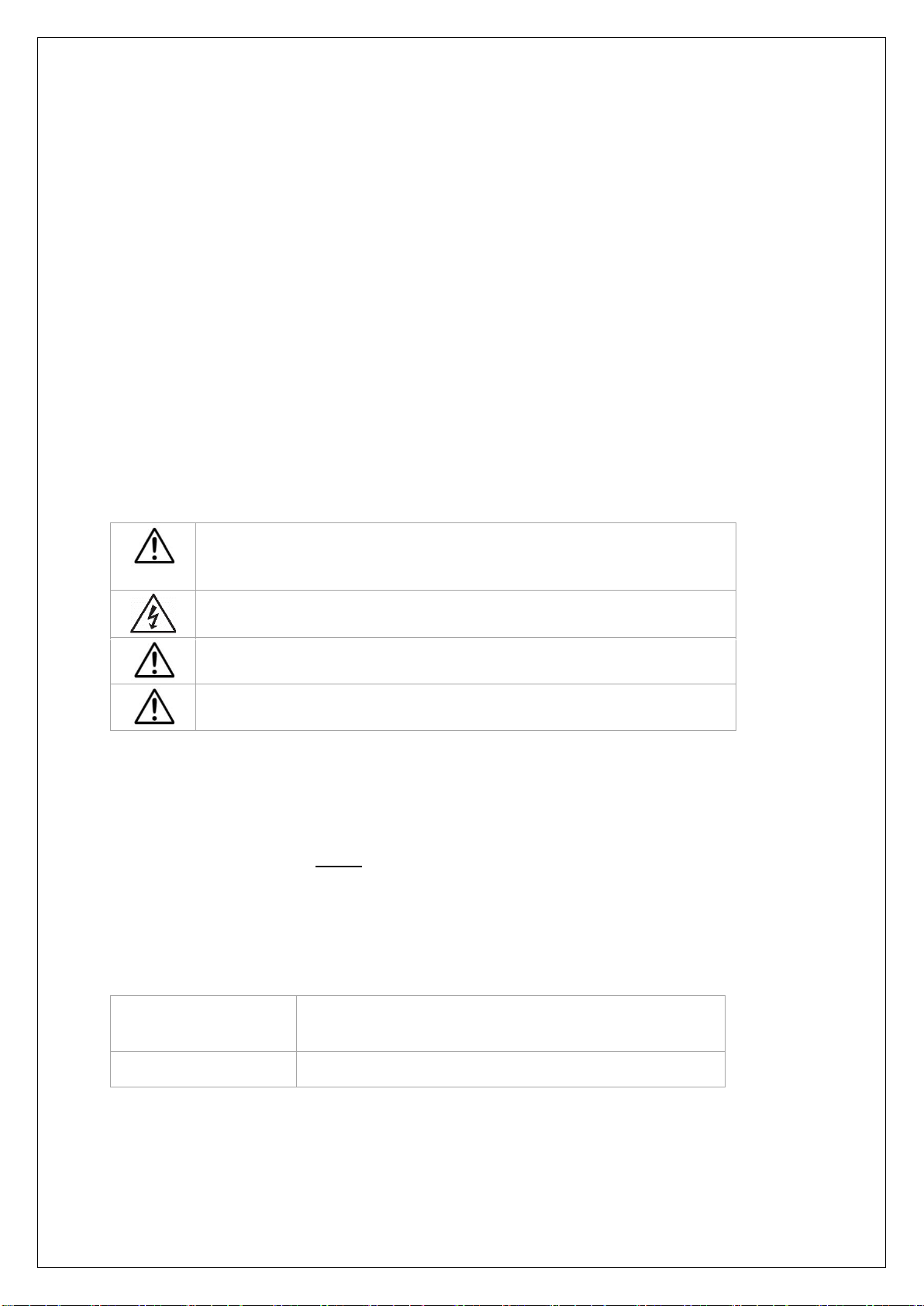
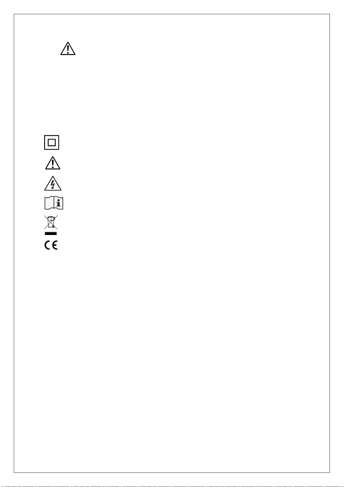
1.8 Symbols
Double insulated device, protection class 2.
Warning for life-threatening or hazardous for properties situations.
Caution, possibility of electric shock
Read the manual before use
The device must be discarded in a professional way
CE conformity mark
3
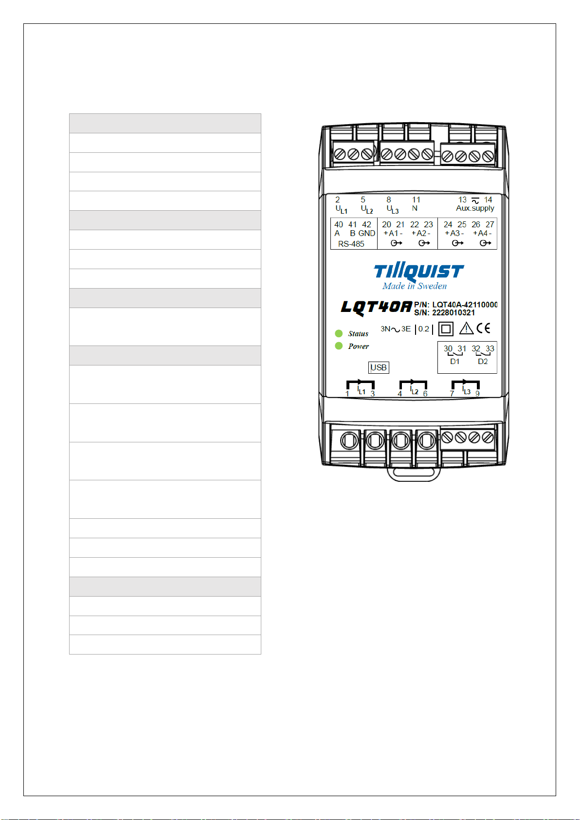
2Connections
2.1 Connection diagram
Voltage input
UL1
2
UL2
5
UL3
8
N
11
Current input
In
Out
IL1
1
3
IL2
4
6
IL3
7
9
Aux Power Supply
13
14
Analog Output
A1
20
21
+
-
A2
22
23
+
-
A3
24
25
+
-
A4
26
27
+
-
Digital Output
D1
30, 31
D2
32, 33
Modbus RS485
A
40
B
41
GND
42
4
2.2 Electric connection
The plug-in terminals needs to be removed before accessing the input terminals.
Inputs L1, L2, L3, N, I1, I2, I3, Aux.supply
Wire section:
6.0 mm² / 10 AWG
Clamp opening size:
3.2 × 3.9 mm
Wire stripping:
max 9 mm
Recommended torque:
0.8 - 0.88 Nm / 7.2 - 7.9 in.lbs
Analog Outputs, Digital Outputs, RS 485 (plug-in terminals)
Wire section:
2.5 mm² / 14 AWG
Clamp opening size:
2.8 × 3.1 mm
Wire stripping:
max 8 mm
Recommended torque:
0.5 - 0.55 Nm / 4.5 - 4.9 in.lbs
2.3 Connection diagrams –System connection
LQT40A system connection is programmable from single phase to 4-wire balanced or unbalanced
connection.
Configurable System Connection
System
connection
Application
I1
I2
I3
U1
U2
U3
N
U12
U23
U31
-00
4wire, 3 phase symmetric load
X
-
-
X
-
-
X
-
-
-
-01
1-wire, 1 phase
X
-
-
X
-
-
X
-
-
-
-02
3-wire, 3 phase symmetric load
X
-
-
-
-
-
-
X
-
-
-03
3-wire, 3 phase symmetric load
X
-
-
-
-
-
-
-
X
-
-04
3-wire, 3 phase symmetric load
X
-
-
-
-
-
-
-
-
X
-05
3-wire, 3 phase symmetric load
X
-
-
X
X
X
-
X
X
X
-09
3-wire, 3 phase asymmetric load
X
-
X
X
X
X
-
X
X
X
-11
4-wire, 3 phase asymmetric load
X
X
X
X
X
X
X
X
X
X
-11
4-wire, 3 phase asymmetric load Open Delta
X
X
X
X
X
X
-
X
X
X

5
-00
1-phase
1 element
4-wire
3-phase symmetric load
-01
1-phase
1 element
2-wire
Single-phase AC
-02
1-phase
1 element
3-wire
3-phase symmetric load phase-shift U12-I1
-03
1-phase
1 element
3-wire
3-phase symmetric load phase-shift U23-I1
-04
1-phase
1 element
3-wire
3-phase symmetric load phase-shift U31-I1

6
-05
3-phase
1 element
3-wire
3-phase symmetrical load
-09
3-phase
2 elements
3-wire
3-phase asymmetrical load
-11
3-phase
3 elements
4-wire
3-phase asymmetrical load

7
3Measuring
3.1 Measured quantities
Prefix
Quantity
Calculation
System / Phase
I
Input current
(I1+I2+I3)/3
System
I1
Phase current L1
L1
I2
Phase current L2
L2
I3
Phase current L3
L3
U
Input voltage
(U1+U2+U3)/3
System
U1
L1 Phase voltage
L1
U2
L2 Phase voltage
L2
U3
L3 Phase voltage
L3
P
Active power
P1+P2+P3
System
P1
Active power L1
L1
P2
Active power L2
L2
P3
Active power L3
L3
Q
Reactive power
Q1+Q2+Q3
System
Q1
Reactive power L1
L1
Q2
Reactive power L2
L2
Q3
Reactive power L3
L3
S
Apparent power
S1+S2+S3
System
S1
Apparent power L1
L1
S2
Apparent power L2
L2
S3
Apparent power L3
L3
U12
Main voltageL1-L2
L1 - L2
U23
Main voltage L2-L3
L2 - L3
U31
Main voltage L3-L1
L3 - L1
PF
Active power factor
P/S
System
PF1
Active power factor
COS(φ1)=P1/S1
L1
PF2
Active power factor
COS(φ2)=P2/S2
L2
PF3
Active power factor
COS(φ3)=P3/S3
L3
QF
Reactive power factor
Q/S
System
QF1
Reactive power factor
SIN(φ1)=Q1/S1
L1
QF2
Reactive power factor
SIN(φ2)=Q2/S2
L2
QF3
Reactive power factor
SIN(φ3)=Q3/S3
L3
LF
LF factor
sign(Q)*(1-|PF|)
System
LF1
LF factor
sign(Q1)*(1-|PF1|)
L1
LF2
LF factor
sign(Q2)*(1-|PF2|)
L2
LF3
LF factor
sign(Q3)*(1-|PF3|)
L3
PA
Phase angel
PA=(PA1+PA2+PA3)/3
System
PA1
Phase angel
φ1=ARCCOS(P1/S1)/PI*180*sign(P1)
L1
PA2
Phase angel
φ2=ARCCOS(P2/S2)/PI*180*sign(P2)
L2
PA3
Phase angel
φ3=ARCCOS(P3/S3)/PI*180*sign(P3)
L3
IS
Input current with sign
(IS1+IS2+IS3)/3
System
IS1
Phase current with sign
I1*sign(P1)
L1
IS2
Phase current with sign
I2*sign(P2)
L2
IS3
Phase current with sign
I3*sign(P3)
L3
P_I1_U12
Active power, System connection-02
System
P_I1_U23
Active power, System connection -03
System
P_I1_U31
Active power, System connection -04
System
Q_I1_U12
Reactive power, System connection -02
System
Q_I1_U23
Active power, System connection -03
System
Q_I1_U31
Active power, System connection -04
System
F
Frequency
System
8
3.2 Meassuring system
3.2.1 Phase-Locked loop - PLL
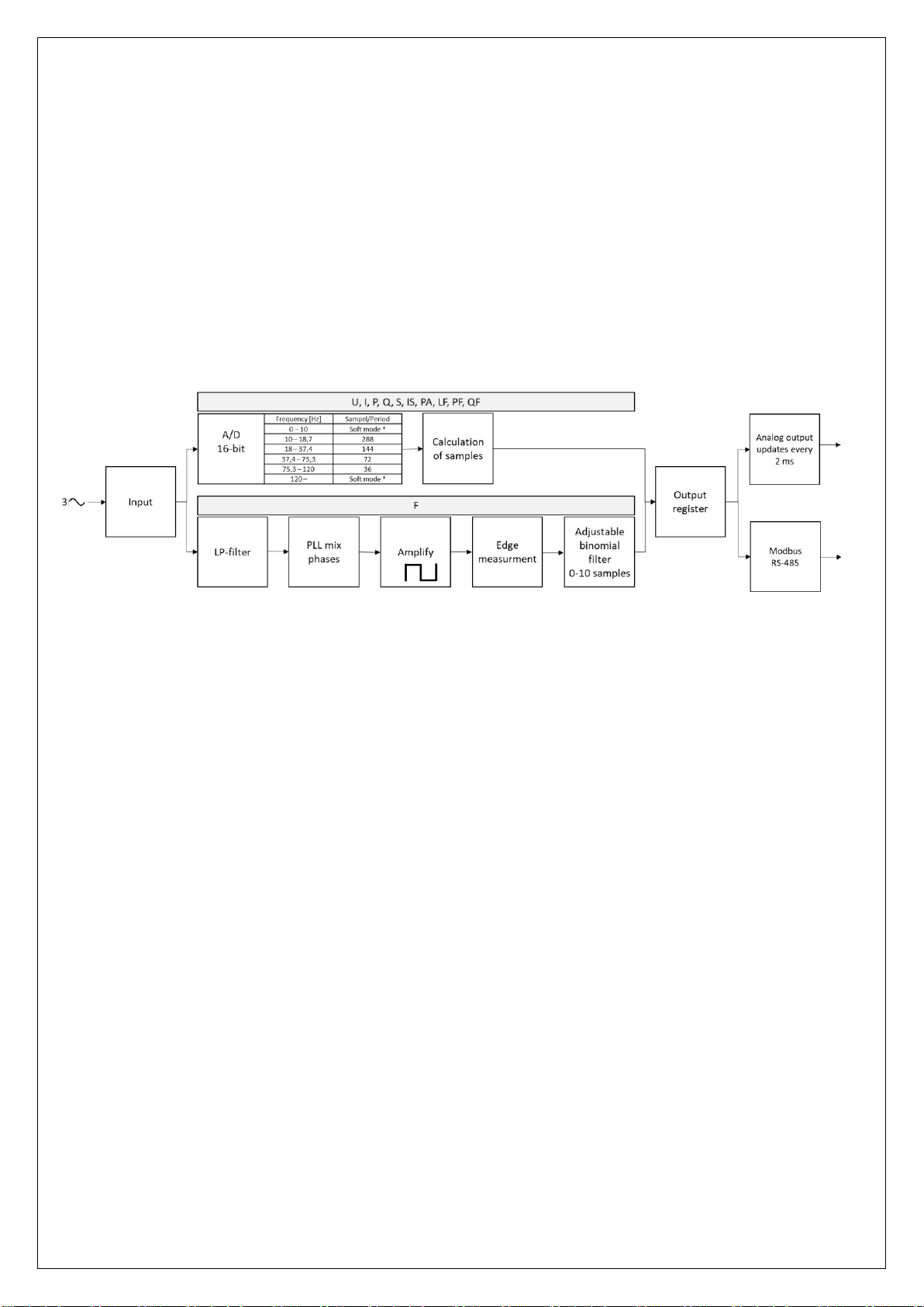
The measuring system use a phase-locked loop (PLL) between 10-120 Hz. All quantities are being
measured. The number of samples per period is deppending of the frequency.
3.2.2 Soft mode
A fixed sample rate of 1800 samples/second (soft mode) is used when the frequency is lower than
10 Hz or higher than 120 Hz. Measured quantities in soft mode are voltage (U), current (I) and
frequency (F).
3.2.3 Block diagram
Schematic block diagram of measure process.
*Soft mode = 1800 samples / second
3.2.4 Frequency filter
The frequency measurement is low-pass filtered with a binomial filter. This setting determines the
length of the filter in periods of the measured frequency. A shorter length gives a more responsive
measurement. A longer length gives a slower, more stable measurement.
Frequency filter is adjustable between 0 –10.
9
4Outputs
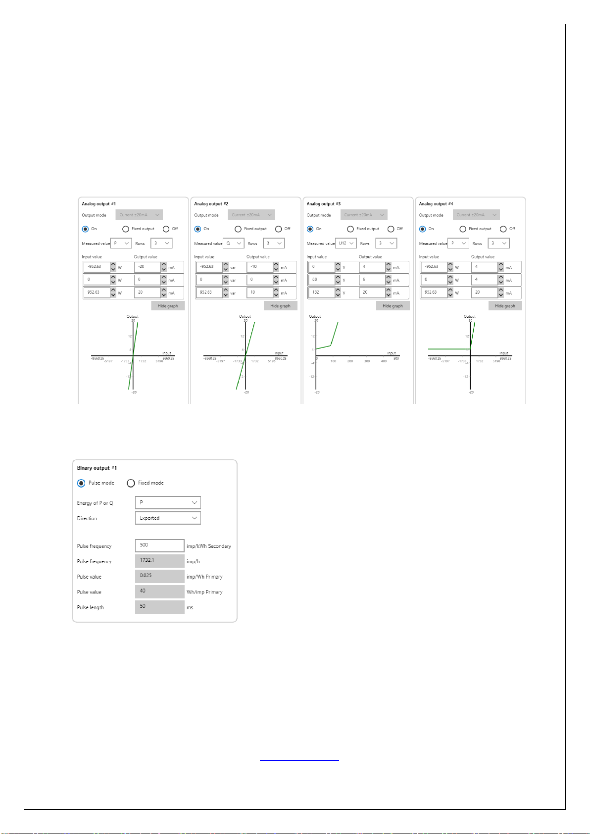
4.1 Analog output
The analog outputs can be assigned any measured quantity, see table ”3.1 Measured quantities”.
The output is available with three different ranges, ±20 mA, ±5 mA or ±10V. The resolution of the
output is 16 bits. 2 to 5 characteristic point can be programmed for each channel. It is possible to
set a fixed value for the output. Fixed output is useful when testing an installation. Off position is
the same as 0 mA or V.
4.2 Digital outputs
Digital output is used to pulse energy, P (active power) or Q (reactive power) as export or import.
4.3 Modbus RS485
4.3.1 Interface Modbus RTU
Protocol: Modbus RTU
Physics: RS-485, max 1200 m (4000 ft)
Baud rate: 2400, 4800, 9600, 19200, 38400 Baud
Number of participants: max 32
For additional information about Modbus: www.modbus.org

10
4.3.2 Modbus mapping
Different Modbus protocol profiles are available, depending of needs and the update frequency of
data.
Modbus protocol profile Mapping 001
The output registry for the measured quantities is updated every 100 ms with profile mapping 001.
adr
format
parameter
explanation
0
binary32
F
Hz
Frequency
system
2
binary32
I
A
Input current
system
I = (I1+I2+I3)/3
4
binary32
I1
A
Phase current
L1
6
binary32
I2
A
Phase current
L2
8
binary32
I3
A
Phase current
L3
10
binary32
U
V
Input voltage
system
U = (U1+U2+U3)/3
12
binary32
U1
V
Phase voltage
L1-N
14
binary32
U2
V
Phase voltage
L2-N
16
binary32
U3
V
Phase voltage
L3-N
18
binary32
U12
V
Main voltage
L1-L2
20
binary32
U23
V
Main voltage
L2-L3
22
binary32
U31
V
Main voltage
L3-L1
24
binary32
P
W
Active power
system
P = P1+P2+P3
26
binary32
P1
W
Active power
L1
28
binary32
P2
W
Active power
L2
30
binary32
P3
W
Active power
L3
32
binary32
Q
var
Reactive power
system
Q = Q1+Q2+Q3
34
binary32
Q1
var
Reactive power
L1
36
binary32
Q2
var
Reactive power
L2
38
binary32
Q3
var
Reactive power
L3
40
binary32
S
VA
Apparent power
system
S = S1+S2+S3
42
binary32
S1
VA
Apparent power
L1
S1 = U1*I1
44
binary32
S2
VA
Apparent power
L2
S1 = U1*I2
46
binary32
S3
VA
Apparent power
L3
S1 = U1*I3
48
binary32
LF
-
LF factor
system
LF = sign(Q)*(1-|PF|)
50
binary32
LF1
-
LF factor
L1
LF1 = sign(Q1)*(1-|PF1|)
52
binary32
LF2
-
LF factor
L2
LF2 = sign(Q2)*(1-|PF2|)
54
binary32
LF3
-
LF factor
L3
LF3 = sign(Q3)*(1-|PF3|)
56
binary32
PF
-
Active power factor
system
PF1 = P/S = COS(φ) = COS(PA)
58
binary32
PF1
-
Active power factor
L1
PF1 = P1/S1 = COS(φ1) = COS(PA1)
60
binary32
PF2
-
Active power factor
L2
PF2 = P2/S2 = COS(φ2) = COS(PA2)
62
binary32
PF3
-
Active power factor
L3
PF3 = P3/S3 = COS(φ3) = COS(PA3)
64
binary32
QF
-
Reactive power factor
system
QF1 = Q/S = SIN(φ) = SIN(PA)
66
binary32
QF1
-
Reactive power factor
L1
QF1 = Q1/S1 = SIN(φ1) = SIN(PA1)
68
binary32
QF2
-
Reactive power factor
L2
QF2 = Q2/S2 = SIN(φ2) = SIN(PA2)
70
binary32
QF3
-
Reactive power factor
L3
QF3 = Q3/S3 = SIN(φ3) = SIN(PA3)
72
binary32
PA
°el
Phase angle φ
system
PA=(PA1+PA2+PA3)/3
74
binary32
PA1
°el
Phase angle φ1
L1
PA1 = ARCCOS(P1/S1)/PI*180*sign(P1)
76
binary32
PA2
°el
Phase angle φ2
L2
PA1 = ARCCOS(P2/S2)/PI*180*sign(P2)
78
binary32
PA3
°el
Phase angle φ3
L3
PA1 = ARCCOS(P3/S3)/PI*180*sign(P3)
80
binary32
IS
A
Input current with sign
system
IS = (IS1+IS2+IS3)/3
82
binary32
IS1
A
Phase current with sign
L1
IS1 = I1*sign(P1)
84
binary32
IS2
A
Phase current with sign
L2
IS2 = I2*sign(P2)
86
binary32
IS3
A
Phase current with sign
L3
IS3 = I3*sign(P3)
120
binary32
CTR
A/A
primary to secondary current transformer ratio (i.e. 600A/1A)
122
binary32
PTR
V/V
primary to secondary potential (voltage) transformer ratio (i.e. 220kV/110V)

11
Modbus protocol profile Mapping 002
The output registry for the measured quantities is updated every 25 ms with profile mapping 002.
adr
format
parameter
explanation
0
binary32
F
Hz
Frequency
system
2
binary32
I
A
Input current
system
I = (I1+I2+I3)/3
4
binary32
I1
A
Phase current
L1
6
binary32
I2
A
Phase current
L2
8
binary32
I3
A
Phase current
L3
10
binary32
U
V
Input voltage
system
U = (U1+U2+U3)/3
12
binary32
U1
V
Phase voltage
L1-N
14
binary32
U2
V
Phase voltage
L2-N
16
binary32
U3
V
Phase voltage
L3-N
18
binary32
U12
V
Main voltage
L1-L2
20
binary32
U23
V
Main voltage
L2-L3
22
binary32
U31
V
Main voltage
L3-L1
24
binary32
P
W
Active power
system
P = P1+P2+P3
26
binary32
Q
var
Reactive power
system
Q = Q1+Q2+Q3
Modbus function code 04: Read Input Registers
The data format used is IEEE 754 single-precision binary floating-point format: binary32
Parameters are represented as two consecutive Modbus registers.
The value of a parameter is represented in SI unit as secondary values on transducer input.
To calculate primary values, use the primary to secondary transformer ratio of parameter CTR, PTR
The CTR and PTR parameter can be configured by the user by editing primary to secondary
current- and voltage-ratio in ConfigLQT.

12
5Commissioning
5.1 Programming of the transducer
”ConfigLQT”is a free configuration software, it is availible for download from Tillquist homepage,
www.tillquist.com. The software connects to the transducer and make it possible to change the
configuration of adjustable parameters and to visualize live readings.
ConfigLQT supports offline configuration of adjustable parameters.
Save and load configuration file.
Functionality of ConfigLQT
ConfigLQT allows the user to:
•See online readings of measured values
•Adjust the functionality of the outputs
•Save parameter settings to a file
•Load parameter settings from a file
•Print settings report
•Upgrade firmware
5.2 LED functionality
LQT40A have two LEDs at front, Power and Status.
State
Power
Status
Start-up
Flashing - On 1 sec / Off 0.5 sec
Flashing - On 1 sec / Off 0.5 sec
Normal operation
On
Off
Modbus active
On
Flashing - On 200 ms / Off 200 ms
Error
Flashing - On 100 ms / Off 100 ms
Off

13
6Technical Data
Technical Data
Details
Input
Voltage range (Un)
100 –400 V (L-L) main voltage (nominal)
Measuring range
1 –520 V TRMS L-L 50/60 Hz or
1 - 520 V TRMS L-L 16⅔ Hz
Configurable measuring range
0 - 500 V L-L / 0 - 300 V L-N
Frequency
50/60 Hz (10…40….70…120 Hz)
16⅔Hz (10…15….18…120 Hz)
Overload voltage
1.5 x Un –continuously, 2 x Un –10 s
Consumption
U x 1 mA / phase
Current (In)
1 –5 A
Measuring range
5 mA –10 A TRMS
Configurable measuring range
0 –10 A
Overload current
2 x In continuously, 10 x In 15 s, 40 x In 1 s
Consumption
<0.05 VA / phase
Auxiliary power supply
24 –230 VDC / 90 –230 V AC ±10 %
Burden
max 7.1 W / 15 VA
Output
Analog outputs
4 or 2
Programmable range
±20mA, ±5 mA, ±10V (settings within the range)*
Resolution
16 bits
External resistance load
Current output: max 750 Ω (15 V)
Voltage output: min 750 Ω
Response time
<100 msec
Digital Outputs
2 (Energy pulse output)
Communication
Modbus RS485 (RTU)
General Data
Accuracy
0.2 (Ref. temp. 23 °C)
Galvanic isolation
Supply, in- and output are galvanically isolated
Connection terminals / Torque
Input and Auxiliary power supply: 6 mm2 / 0.8 Nm
Output: 2.5 mm2 / 0.5 Nm
Humidity
95 % non-condensing
USB
USB Micro-B, port for configuration
Temperature
-10…+55 °C (operation)
-40…+70 °C (storage)
Temperature coefficient < 0.1 % / 10 °C
Test voltage
4 kV AC /1 min
Inputs
overvoltage cat. III
Pollution degree
2
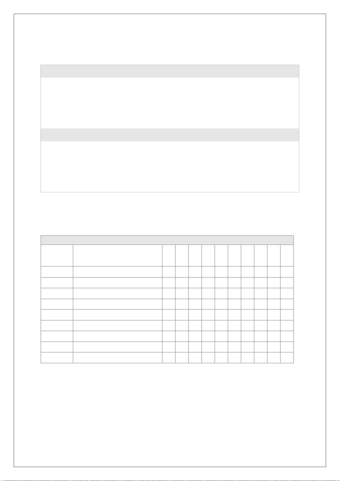
Dimension (W x H x D)
70 x 132 x 101 mm
Weight
330 gr
Protection
IP40 (housing), IP20 (terminals)
Standards
SS-EN 60688 Transducers
SS-EN 61010-1 Safety
EN 61000-6-2 / -6-4 / -6-5
*Depending on the version

14
70 mm
132 mm
Depth
Height
Width
Table of contents
Other TILLQUIST Transducer manuals


Popular Transducer manuals by other brands


MKS
MKS 910-11000-0016 quick start guide

Humminbird
Humminbird APEX Series installation guide

Simrad
Simrad TRANSDUCER - INSTALLATION GENERIC REV H installation manual

HPS
HPS mks 999 Quattro Series Operation and maintenance manual

Faller
Faller 180633 quick start guide

Eaton
Eaton IQ 100 series quick start guide