Timber Tuff Tools CS-BM12 User manual

12-VOLT BAR MOUNT SHARPENER
MODEL# CS-BM12
11182009

SPECIFICATIONS:
- Power supply: 12 volt DC supply
- Wheel thickness: 1/8 inch (3.2mm) and 3/16 inch(4.7 mm)
- Maximum speed: 5500 rpm
- Type of chains: pitches 1/4” ; .325” ; 3/8”
- Weight sharpener: 4.5 lbs (2 kg)
- Accessories: 1 dressing stone; 1 measuring guide. 2 wheels (thickness: 1/8”-3.2mm, 3/16”-4.7mm).
INTRODUCTION
- Save this manual, do not discard or throw away.
- READ THIS MANUAL FIRST. To ensure the correct use of the grinder and to prevent accidents, do not start working
without reading this manual carefully. This manual explains operation and maintenance of this sharpener.
- To guarantee efficient and consistent operation of sharpener, ALWAYS check and replace any worn or broken parts
using ORIGINAL SPARE PARTS ONLY.
For parts or information call: 952-945-9058. 8am to 5pm, USACentral Time.
SAFETY RULES
1. Sharpener is for adult use only. Users must be in good physical and mental condition, and be familiar with the
instructions before use.
2. NEVER wear rings, bracelets and/or loose clothing that could come into contact with the grinding wheel.
3. ALWAYS wear safety gloves and approved protective eyewear while operating or maintaining the
sharpener
4. NEVER stop the grinding wheel with your hands, even after stopping the motor.
5. Check that all power is disconnected when changing grinding wheels, during maintenance, or transporting.
6. NEVER start the sharpener without the wheel guard in place. The guard is supplied in the sharpener package and
must be installed before operation. The guard can be removed ONLY for wheel replacement; then, it must be reinstalled.
7. Check that the voltage and frequency indicated on the sharpener correspond to supplied power.
Never use an alternative rated power supply, as this will damage the sharpener.
8. Never use defective and/or non-standard cables, plugs or extension cables.
9. Remove power or cables immediately if cables show signs of damaged or are cut.
The power supply cables are complete with terminals. Never use cables that are manipulated in any way.
10. Before starting up the sharpener, check that the working area is free of tools or other objects.
11. Check the cable position during operation, making sure that cable stay away from grinding wheels during operation.
Never work near other electrical cables.
12. Never advance the chain with your hands until the grinding wheel has moved entirely back to the upright position
(non- cutting position). Safety gloves should be worn at all times.
13. Other than the operator, keep all humans and pets at least 10’ away from work area during its operation.
14. Before starting the grinder, ALWAYS check that the grinding wheel is correctly installed and not damaged.
15. Always work in a stable and safe position.
16. Always follow maintenance instructions closely.
17. Before using the sharpener, check that all safety devices are properly working.
18. NEVER work with a damaged, improperly repaired, or modified sharpener. NEVER remove, damage, or disconnect
any safety devices.
19. Never use the sharpener as a cutter or for grinding objects other than saw chains.
20. Operators should be have read manuals and be familiar power tools.
21. When not in-use, store the sharpener in a dry place, out of reach. Keep away from children.
22. Do not use in a place where children may be present.
23. The sharpener-motor can be used continuously for 20 minutes; then, it needs to be turn off to cool down to avoid
possible damage from over- heating.
24. Never allow the sharpener near wet areas/environments, or in any place accessible to children.
25. Never use near or expose sharpener to any explosive or flammable liquids or environment.
26. ALWAYS dispose sharpener properly, check with local laws for disposing products.
27. If sharpening a chain on an electrical saw, ALWAYS disconnect the electrical saw POWER CABLE.
30. NEVER start the sharpener with hands or fingers touching or near wheel.
31. NEVER force the sharpener or any tool while working, maintaining or sharpening.

ASSEMBLY AND WARNINGS
ABOUT THE GRINDING WHEEL
There are two types of grinding wheels, 1 / 8 "and 3 / 16" for sharpening chains from 1/4” to 3/8”pitch.
To replace or change grinding wheels:
Always disconnect from any power source
Remove blade protective shield, by removing screw at top of shield then pulling upward (straight up). You may need
to pull hard to remove.
See FIGURE#3 below for properly securing grinding wheels with plastic nut. Be sure plastic secure nut is assembled
in correct direction as per figure 3.
ALWAYS CHECK GRINDING WHEEL FOR ANY DAMAGE BEFORE USE
START-UP
FIRST: Check that you have proper size grinding wheel to match your chain.
Check your chainsaw CHAIN mfg specifications for proper wheel size, and/or refer to chart below.
Be sure the wheel is securely installed and ALWAYS check wheel for any damage BEFORE EACH USE.
NEVER use without wheel guard installed.
NEXT: Install the sharpener onto chainsaw chain bar, approximately centered.
- Notes: Always hit the STOP/RED off switch to stop the grinder. The provided power cables are complete with
terminals for quick and safe connection to any 12volt battery (SEE fig. 5). This allows the operator to use this sharpener
on-the-job or in-the-field, wherever a 12volt battery is available.

SHARPENING
ALWAYS clean the chain before sharpening
First:
Find the correct cutting angles needed by referring to chart provided. You will need your chain pitch and gauge. Refer to
your CHAIN mfg. specifications first, then use chart provided.
- Then adjust the cutting angle on the sharpener, using the black knob to obtain the correct angle.
- If possible, start grinding right-hand teeth first; starting from the worst tooth identified using the template/guide.
(SEE FIG. 4 – point D)
Next:
- Test your set-up before turning on the sharpener (BEFORE EACH USE)
- Tilt the wheel motor casing toward the operator, so the cutting part of the wheel slightly touches the tooth to
be sharpened
- Loosen the wing nut at the back of the sharpener, so the chain stop hits the back of the tooth
- Move the chain stop manually, so the wheel touches the tooth slightly for sharpening
(To adjust the amount of tooth that will be sharpened)
- Tighten the wing nut at the back of the grinder to keep chain stop in position.
READY TO SHARPEN:
Start the sharpener, slowly tilting the wheel towards the operator, to sharpen/work the first tooth;
- At this point, set the grinding depth by adjusting the wing bolt on the side of the grinder.
- After determining the amount of tooth to be sharpened, the wing bolt will be held in this position by a spring
- After completing above for the first tooth, complete all the “right” teeth
Once all right teeth have been sharpened, stop the grinder
- Rotate the grinder head to the same angle degree as the right side by loosening the black knob
- Stand near the side facing the bar, to avoid the any sparks caused by sharpening
- Position the rear part of a left tooth against the chain stop
- Start the grinder, slowly tilting the wheel towards the operator, to sharpen/work the tooth;
At this point, set the same grinding depth that was set for right teeth, by adjusting the wing bolt on the side of the grinder
- After determining the amount of tooth to be sharpened, the wing bolt will be held in this positioned by a spring
- After completing the above for first tooth, complete grinding of all the “left” teeth
NOTE: To avoid overloading the motor and to prevent the chain from being damaged, remove small amounts of material
and do not work too long on the same tooth, so you do not to damage the cutter (tooth). A good method is to pull the
sharpener blade to the tooth being sharpened two-three times before going to the next tooth.
Once sharpening is complete, turn off the sharpener, disconnect the cables from the battery or power source, remove the
sharpener from the Chainsaw Bar and place in a safe place out of the reach of children.
TROUBLESHOOTING
The grinder does not start:
- check that power supply is fully charged and cables are connected with no corrosion on battery.
- check that cables of the grinder are not damaged
The grinder’s electrical motor is overheated:
- check that the voltage indicated on the motor matches the battery (maximum 12volt battery)
- note that the maximum time (20 min.) is recommended for continuous motor operation
- check that grinding wheel is not blocked during grinding.
The direction of rotation of the wheel is the opposite of that indicated on the machine:
- check that your cables are properly connected to battery (positive / negative)
The machine shows signs of vibrations:
- check that the sharpener is secured to the bar of the chainsaw (motor-driven or electrical)
- check that the motor unit is secured to the base unit
- check that the grinding wheel is properly installed. Always check for cracked or broken blades.
If above problems persist, you may need to contact a local repair center or shop.

MAINTENANCE
- Always disconnect from power source before carrying out any maintenance, lubrication or cleaning operations
- Keep sharpener clean using a cloth rag with soap and water. Always dry after cleaning
ALWAYS keep safety labels clearly legible.
- NEVER use compressed air for cleaning, it can cause wood or metal dust to reach small areas in the sharpener causing
damage to essential components of the sharpener.
FIG
.
3
FIG
.
5
FIG
.
4
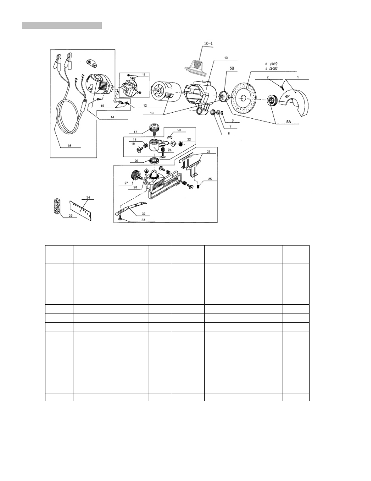
DIAGRAM AND PARTS LIST
Parts # Description Qty Parts # Description Qty
1 Grinding wheel cover 1 16 Cable Set 1
2 Self-tapping screw 1 17 lock nut 1
3 Grinding wheel 1 18 Reset spring 4
4 Grinding wheel 1 19 Adjustment bolt 4
5A Grinding wheel cover
board 1 20 Torsion limit board 1
5B Grinding wheel seat 1 22 Torsion 1
6 Axis Card 1 23 Elastic clip chain plate 2
7 Antifriction pad 1 24 Rotating Seat 1
8 Torsion Cover 2 25 bearing spring 2
10 Body 1 26 Angle plate 1
10-1 Handle 1 27 lock nut 1
11 PCB board 1 28 M5 nut 1
12 Pressure Line board 1 32 Limited board Set 1
13 Electrical Set 1 33 bolt M5X10 1
14 Self-tapping screw 4 34 Gauge 1
Switch Cover 1 35 Shaping of sand 1

ABC D E F G HI M
Chain
Pitch Gauge
.Sharpe
ning
Angle
Wheel
Thickne
ss
Depth
Gauge
1/4” 050”/1.3m
m25AP 13RM 50K 16 30° 1/8”/3.2m
m.025”/0.63
mm
325” 050”/1.3m
m33LG 23RS 50JG K1L 920S 25° 1/8”/3.2m
m.025”/0.63
mm
325” 058”/1.5m
m34LG 25RS 58JG K2L 928S 25° 1/8”/3.2m
m.025”/0.63
mm
325” 063”/1.6m
m35LG 26RS 63JG K3L 963S 25° 1/8”/3.2m
m.025”/0.63
mm
325” 050”/1.3m
m20LP 23RS 50JLG K1L 920 25° 1/8”/3.2m
m.025”/0.63
mm
325” 058”/1.5m
m21LP 25RS 58JLG K2L 928 25° 1/8”/3.2m
m.025”/0.63
mm
325” 063”/1.6m
m22LP 26RS 63JLG K3L 923 25° 1/8”/3.2m
m.025”/0.63
mm
325” 050”/1.3m
m20BP 23RM 50J KIC 520 30° 1/8”/3.2m
m.025”/0.63
mm
325” 058”/1.5m
m21BP 25RM 58J K2C 528 30° 1/8”/3.2m
m.025”/0.63
mm
325” 063”/1.6m
m22BP 26RM 63J K3C 523 30° 1/8”/3.2m
m.025”/0.63
mm
325” 050”/1.3m
m95VP 520P 30° 1/8”/3.2m
m.025”/0.63
mm
325” 050”/1.3m
m95R 5° 1/8”/3.2m
m.030”/0.76
mm
325” 058”/1.5m
mM21LP 25° 1/8”/3.2m
m.025”/0.63
mm
325” 063”/1.6m
mM22LP 25° 1/8”/3.2m
m.025”/0.63
mm
3/8” 050”/1.3m
m72LG 33RS 50AL A1LM 980D
25°
1/8”/3.2m
m -
3/16”/4.7m
m
.025”/0.63
mm
3/8” 058”/1.5m
m73LG 35RS 58AL A2LM 988D
25°
1/8”/3.2m
m -
3/16”/4.7m
m
.025”/0.63
mm
3/82 0632/1.6m
m75LG 36RS 63AL A3LM 983D
25°
1/8”/3.2m
m -
3/16”/4.7m
m
.025”/0.63
mm
3/8” 050”/1.3m
m72LP 33RS 50ALG A1L 980
25°
1/8”/3.2m
m -
3/16”/4.7m
m
.025”/0.63
mm
3/82 058”/1.5m
m73LP 35RS 58ALG A2L 988
25°
1/8”/3.2m
m -
3/16”/4.7m
m
.025”/0.63
mm
3/8” 058”/1.5m
m73VL
25°
1/8”/3.2m
m -
3/16”/4.7m
m
.025”/0.63
mm
3/8” 063”/1.6m
m75LP 36RS 63ALG 983 25° 1/8”/3.2m
m -
3/16”/4.7m
.025”/0.63
mm

m
3/8” 050”/1.3m
m72DG 33RM 50A A1EP 747
30°
1/8”/3.2m
m -
3/16”/4.7m
m
.025”/0.63
mm
3/8” 058”/1.5m
m73DG 35RM 58A A2EP 737
30°
1/8”/3.2m
m -
3/16”/4.7m
m
.025”/0.63
mm
3/8” 063”/1.6m
m75DG 36RM 63A A3EP 727
30°
1/8”/3.2m
m -
3/16”/4.7m
m
.025”/0.63
mm
3/8” 050”/1.3m
m72DP 33RM1 50AG A1EP
35°
1/8”/3.2m
m -
3/16”/4.7m
m
.025”/0.63
mm
3/8” 058”/1.5m
m73DP 58AG A2EP
35°
1/8”/3.2m
m -
3/16”/4.7m
m
.025”/0.63
mm
3/8” 063”/1.6m
m75DP 36RM1 63AG A3EP
35°
1/8”/3.2m
m -
3/16”/4.7m
m
.025”/0.63
mm
3/8” 050”/1.3m
m72L
25°
1/8”/3.2m
m -
3/16”/4.7m
m
.025”/0.63
mm
3/8” 058”/1.5m
m73L
25°
1/8”/3.2m
m -
3/16”/4.7m
m
.025”/0.63
mm
3/8” 063”/1.6m
m75L
25°
1/8”/3.2m
m -
3/16”/4.7m
m
.025”/0.63
mm
3/8” 050”/1.3m
m72RD
10°-15°
1/8”/3.2m
m -
3/16”/4.7m
m
.025”/0.63
mm
3/8” 058”/1.5m
m73RD
10°-15°
1/8”/3.2m
m -
3/16”/4.7m
m
.025”/0.63
mm
3/8” 063”/1.6m
m75RD 36RMX
10°-15°
1/8”/3.2m
m -
3/16”/4.7m
m
.025”/0.63
mm
3/8” 058”/1.5m
mM73LP
25°
1/8”/3.2m
m -
3/16”/4.7m
m
.025”/0.63
mm
3/8” 063”/1.6m
mM75LP
25°
1/8”/3.2m
m -
3/16”/4.7m
m
.025”/0.63
mm
3/8(90) 043”/1.1m
m90SG 63PMN N4C
30°
1/8”/3.2m
m -
3/16”/4.7m
m
.025”/0.63
mm
3/8(91) 050”/1.3m
m91 VS 63PM 50R N1C 357
30°
1/8”/3.2m
m -
3/16”/4.7m
m
.025”/0.63
mm
3/8(91) 050”/1.3m
m91VG 63PM1 50RG NIC-BL 357S
30°
1/8”/3.2m
m -
3/16”/4.7m
m
.025”/0.63
mm
3/8(91) 050”/1.3m
m91R 63PMX
5°
1/8”/3.2m
m -
3/16”/4.7m
m
.025”/0.63
mm
404” 058”/1.5m
m58LG B2LM 25° 3/16”/4.7m
m.025”/0.63
mm
404” 063”/1.6m 59LG B3LM 25° 3/16”/4.7m .025”/0.63

m m mm
404” 058”/1.5m
m26/P 58B B2EP 858 35° 3/16”/4.7m
m.030”/0.76
mm
404” 063”/1.6m
m27/P 46RSF 63B B3EP J63 35° 3/16”/4.7m
m.030”/0.76
mm
404” 063”/1.6m
m59AC 46RM 63BC B3S 463 35° 3/16”/4.7m
m.030”/0.76
mm
404” 063”/1.6m
m59CP 35° 3/16”/4.7m
m.030”/0.76
mm
404” 063”/1.6m
m27R 46RMX 63BR B3HR 757 10°-15° 3/16”/4.7m
m.030”/0.76
mm
404” 063”/1.6m
m16H 46RMH HC B3M 757MK 35° 3/16”/4.7m
m.050”/1.27
mm
404” 080”/2.0m
m18H 49RMH 2HC B5M MKII 2000 35° 3/16”/4.7m
m.050”/1.27
mm
PO BOX 5236
HOPKINS, MN 55343
PH: 952-945-9058
FX: 952-945-0066
www.bacindustries.com
Table of contents
Other Timber Tuff Tools Power Tools manuals


