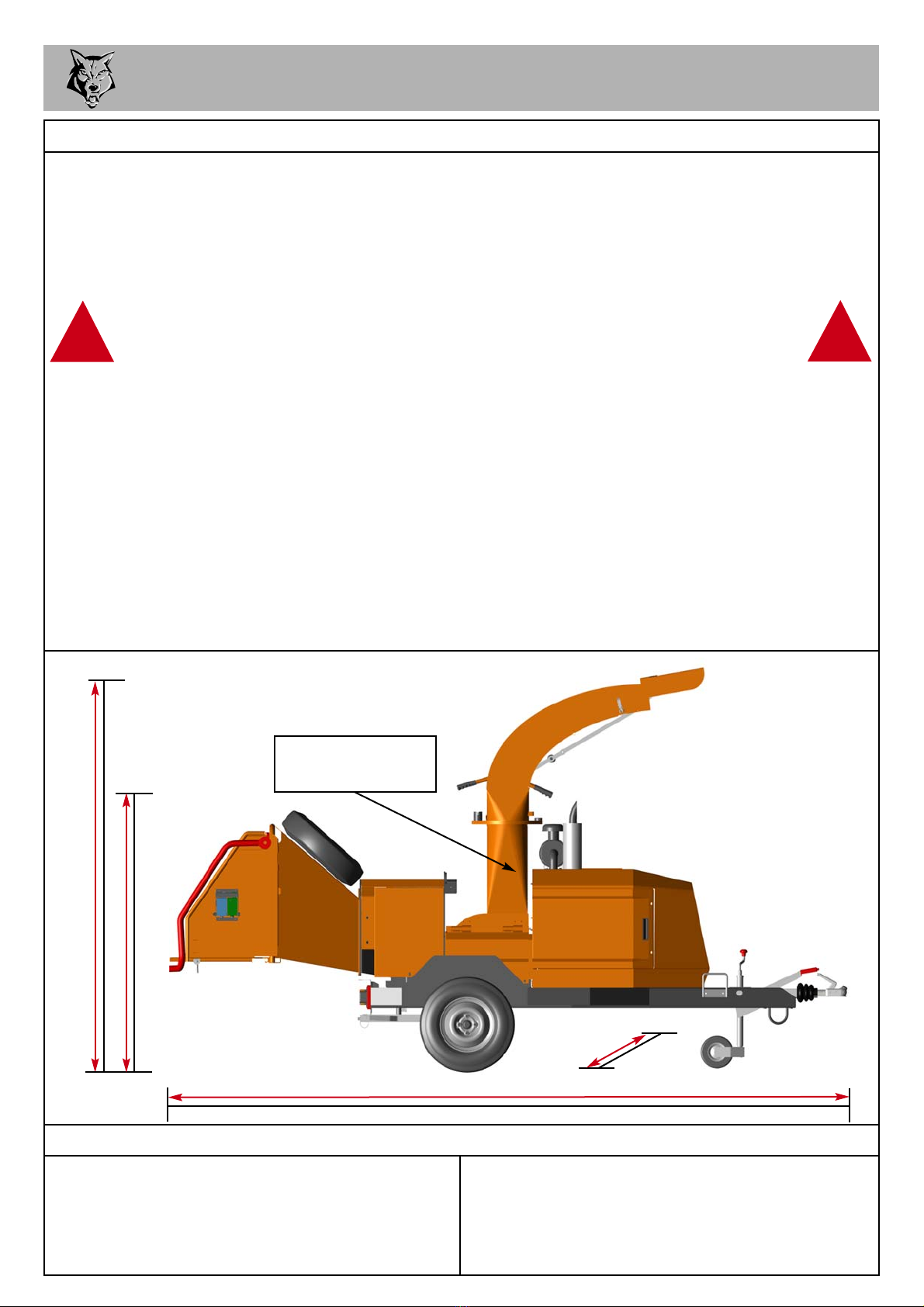
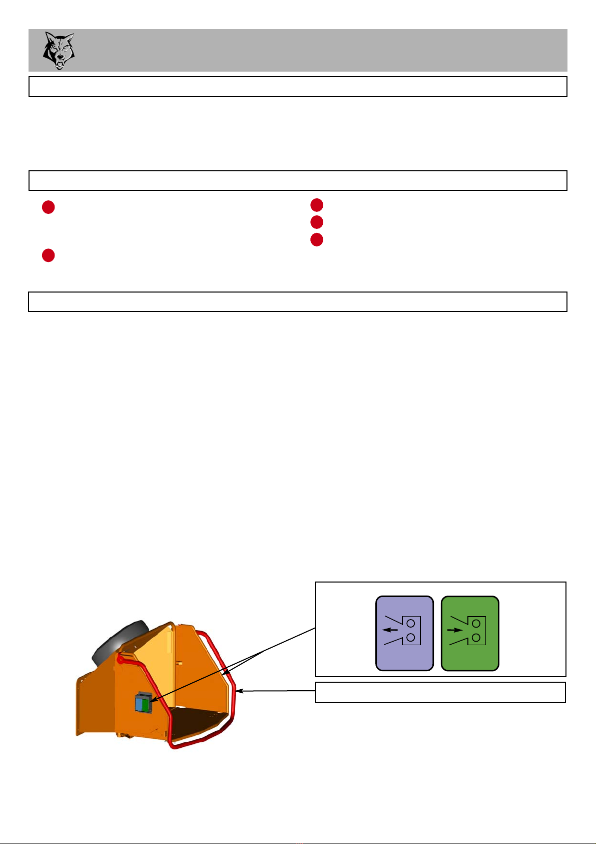
Timberwolf TW S426TDHB User manual

CONTENTS
Section Page No.
INTRODUCTION 1
PURPOSE OF MACHINE 2
MACHINE DIMENSIONS & SPECIFICATIONS 2
PARTS LOCATION DIAGRAMS 3 & 4
SAFE WORKING 5
Operator’s Personal Protective Equipment Required 5
Basic Shredding Safety 5
General Safety Matters - Do’s and Dont’s 6
Noise Test 7
OPERATING INSTRUCTIONS 8
Safe Transportation 8
Hitching onto the Tow Ball 8
Unhitching the Shredder 8
Delivery 9
Operator’s Personal Protective Equipment Required 9
Manual Controls 9
Auto Controls 10
Daily Checks Before Starting 10
Engine Controls 10
Starting the Engine 10
Controlling the Engine Speed 10
Stopping the Engine 11
Before Using the Shredder 11
Starting to Shred 11
Discharge Controls 11
Hydraulic Oil Lever Indicator 12
Fuel Level Indicator 12
Shredding 12
Blockages 12
SERVICE INSTRUCTIONS 13
Service Schedule 14
Safe Maintenance 15
Spares 15
Safe Lifting of the Shredder 15
Change Hydraulic Oil and Filter 16
Copper Ease Safety Information 16
Battery Removal and Maintenance 16
Battery Safety Information 16
Check Fittings 18
Check Free Rotation of Rotor Drum and Hammers 18
Change Hammers 19
Check Hoses 19
Grease Drum Bearings 20
Tension Drive Belts 20
Grease the Roller Box Slide 21
Grease the Roller Spline and Bearing 21
Grease Jack Stand 21
Grease the Discharge Flange 21
Engine Manufacturer’s Handbook 21
WARRANTY STATEMENT 22
EC DECLARATION OF CONFORMITY CERTIFICATE 23
IDENTIFICATION PLATES 24
DECALS 25 & 26
ELECTRICAL DETAIL 27
HYDRAULIC LAYOUT 28
CIRCUIT DIAGRAM 29
PARTS LISTS 30 - 45
29th Oct 08

TIMBERWOLF S426TDHB 1
Thank you for choosing this Timberwolf shredder. Timberwolf shredders are designed
to give safe and dependable service if operated according to the instructions.
Before using your new shredder, please take time to
read this manual which contains
IMPORTANT HEALTH AND SAFETY INFORMATION
and explains the shredder controls. Failure to do so could result in:
- personal injury
- equipment damage
- damage to property
- a member of the general public becoming injured
This manual covers the operation and maintenance of the Timberwolf S426TDHB.All
information in this manual is based on the latest product information available at the
time.
All the information you need to operate the machine safely and effectively is contained
within pages 3 to 12. Ensure that all operators are adequately trained for operating
this machine, especially with regard to safe working practices.
Timberwolf's policy of constantly improving their products may involve major or minor
changes to the shredders or their accessories. Timberwolf reserves the right to make
changes at any time without notice and without incurring any obligation.
Due to improvements in design and performance during production there may be, in
some cases, minor discrepancies between the actual shredder and the text in this
manual.
The manual should be considered a permanent part of the
machine and should remain with it if the machine is resold.
CAUTION or WARNING
Be aware of this symbol and where shown,
carefully follow the instructions.
This caution symbol indicates important safety messages in this manual. When
you see this symbol, be alert to the possibility of injury to yourself or others, and
carefully read the message that follows.
Always follow safe operating and maintenance practices
INTRODUCTION
!

Serial No. Location
The serial number plate can
be located here.
725mm
DIMENSIONS
2220mm
4220mm with standard tow head (3600mm with feed tray folded)
1506mm
PURPOSE OF MACHINE
Engine type Kubota 4-cylinder turbo diesel
Maximum power 33kW (45hp)
Cooling method Water cooled
Overall weight 1350kg
Starting method Electric
Roller feed Hydraulic motor
Maximum diameter material 225mm (9")
Fuel capacity 33 litres
Hydraulic oil capacity 15.5 litres
Material processing capacity up to 3 tonnes/hr
Fuel type Diesel
TIMBERWOLF S426TDHB SPECIFICATION
TIMBERWOLF S426TDHB 2
TIMBERWOLF
S426 TURBO SHREDDER
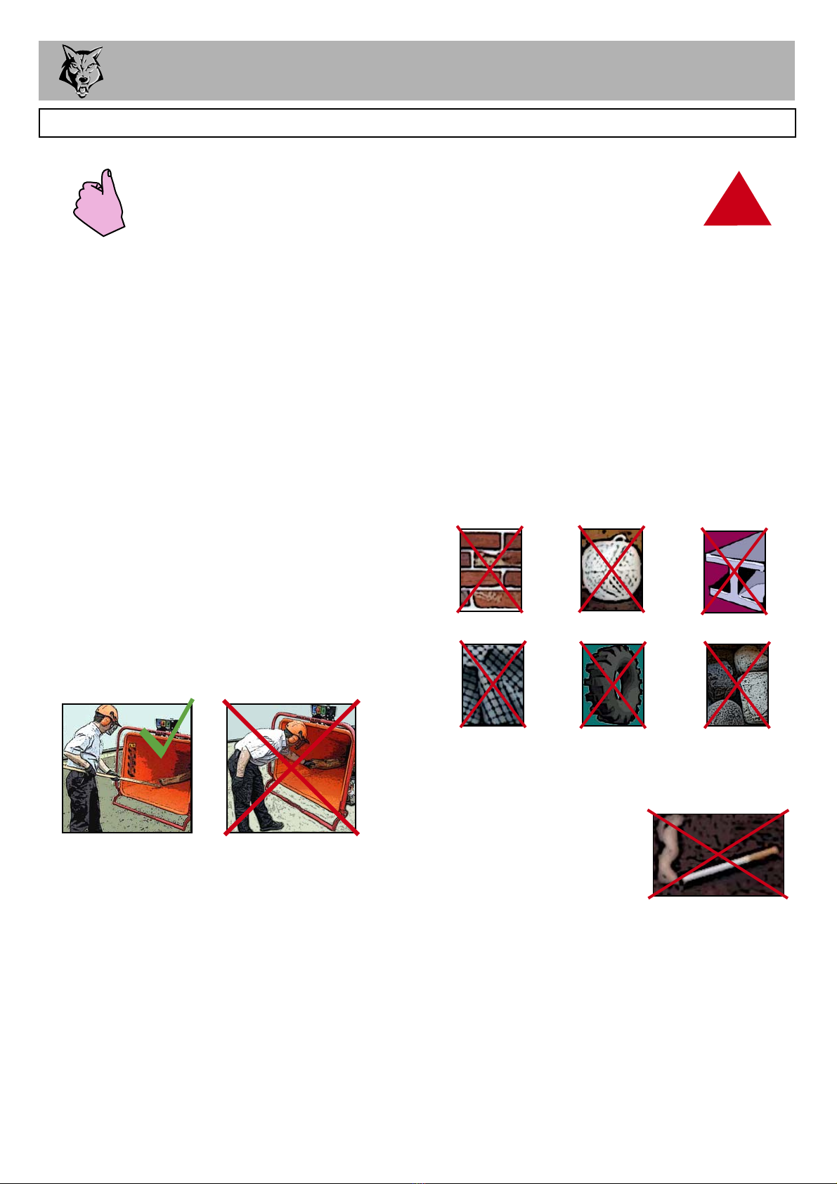
WARNING - LIMITATIONS ON MATERIALS.
To properly control the speed of material entering the shredder chamber, the machine
relies on the large feed roller to grip the material. The feed roller can grip material down to 15mm in diameter.
The machine will not tolerate or process items such as tyres, mattresses, heavy duty plastic containers (used
for oils, chemicals, etc.), carpets, reinforced concrete, metallic items exceeding lightweight domestic door
furniture, commercial plastic gas pipe, alkathene water pipe, metal reinforced drainage/irrigation pipe, baler
twine, rope, metal banding, computer hard drives (which contain magnets) and any similar objects to the
above.
Ejection of material – Warning! The S426TDHB shredder ejects material at high speed. Ensure there is an
adequate safety zone and that ejected material is aimed away from operators into a safe area, i.e. an
enclosure or container with a back stop (i.e. wall) behind it to prevent ejected material from leaving the work
area and causing injury and damage. If loading into a truck or trailer, ensure the structure is strong enough to
cope with the impact from ejected material.
!!
The Timberwolf S426TDHBis a high speed, heavy duty professional shredder. It is designed to shred general
green waste (brash, prunings, hedge trimmings, Leylandii, Christmas trees, rootballs, etc.),brushwood up to
150mm (6”), pallets, domestic doors, wooden and plastic window frames (all pre-cut to fit feed aperture),
contaminated timber, chipboard, MDF, packaging materials, uPVC plastic, cardboard, wooden furniture, fence
posts and similar items. The machine will tolerate drinks cans, plastic bottles, stones, rocks and concrete (up
to fist size), nails, metal door furniture, glass bottles and similar items.

PARTS LOCATOR 3
FEED FUNNEL
DISCHARGE
TUBE
DISCHARGE
BUCKET
SAFETY BAR
ROTOR
HOUSING
FUEL TANK
ENGINE
GUARD
TOW HEAD
ROLLER
CONTROLS
DISCHARGE
ADJUSTMENT
CONTROL AIR INTAKE
EXHAUST
FEED TRAY
TIMBERWOLF
S426 TURBO SHREDDER
SPARE WHEEL
CLEARING
PLATE

PARTS LOCATOR 4
JOCKEY
WHEEL
ASSEMBLY
BATTERY
ROTOR
PULLEY
DRIVE
PULLEY
FUEL
PUMP
DIP
STICK
OIL FILTER
ALTERNATOR
ENGINE
CONTROL PANEL
STARTER
MOTOR
RADIATOR
TOP
ROLLER
SLIDE
DIRECTIONAL
CONTROL
VALVE
RESERVE TANK
HYDRAULIC
OIL TANK
HYDRAULIC
OIL FILTER
MOTOR
ROTOR
DRUM
HAMMERS
THROTTLE

SAFE WORKING 5
BASIC SHREDDING SAFETY
The operator should be aware of the following points:
MAINTAIN A SAFETY EXCLUSION ZONE around the shredder of at least 10 metres for the
general public or employees without adequate protection. Due to the nature of material being
shredded and the distance/velocity of discharge, the exclusion zone must be extended to 20
metres in front of the discharge tube exit. Use hazard tape to identify this working area and
keep it clear from debris build up. Shredded material should be ejected away from any area the
general public have access to.
HAZARDOUS MATERIAL - Some species of trees and bushes are poisonous. The shredding
action can produce vapour, spray and dust that can irritate the skin. This may lead to
respiratory problems or even cause serious poisoning. Check the material to be shredded
before you start. Avoid confined spaces and use a facemask if necessary.
BE AWARE when the shredder is processing material that is an awkward shape. The material
can move from side to side in the funnel with great force. If the material extends beyond the
funnel, the brash may push you to one side causing danger.
BE AWARE that the shredder can eject material out of the feed funnel with considerable force.
Always wear full head and face protection.
ALWAYS work on the side of the machine furthest from any local danger, e.g. not road side.
WARNING
The shredder will feed material through on its own. To do this, it relies on
the hammers to be free to swing. DO NOT put bricks, large stones, string,
carpet, tyres or metal into the shredder. !
!
OPERATOR'S PERSONAL PROTECTIVE EQUIPMENT REQUIRED
Chainsaw safety helmet
fitted with mesh visor and
recommended ear defenders
to the appropriate
specifications.
Work gloves with
elasticated wrist.
Close fitting heavy-duty
non-snag clothing.
Face mask if
appropriate.
DO NOT
wear rings, bracelets,
watches, jewellery or any
other items that could be
caught in the material and
draw you into the shredder.
Steel toe cap safety boots.

SAFE WORKING 6
GENERAL SAFETY MATTERS
DO NOT use shredder unless available light is
sufficient to see clearly.
DO NOT use or attempt to start the shredder
without the feed funnel, belt guard, guards and
discharge unit securely in place.
DO NOT start the shredder running unless
properly guarded.
DO NOT stand directly in front of the feed funnel
when using the shredder. Stand to one side.
DO NOT allow -
DO NOT smoke when
refuelling. Petrol/diesel fuel is
explosive!
DO NOT let anyone who has
not received instruction operate the machine.
DO NOT climb on the machine at any time.
DO NOT handle material that is partially engaged
in the machine.
DO NOT touch any exposed wiring while
machine is running.
- to enter the machine, as damage is likely.
ALWAYS stop the shredder engine before
making any adjustments, refuelling or cleaning.
ALWAYS check machine has stopped rotating
and remove shredder ignition key before
maintenance of any kind, or whenever the
machine is to be left unattended.
ALWAYS check machine is well supported and
cannot move.
ALWAYS run with the engine set to maximum
speed.
ALWAYS check (visually) for fluid leaks.
ALWAYS take regular breaks. Wearing personal
protective equipment for long periods can be
tiring and hot.
ALWAYS keep hands, feet and clothing out of
feed opening, discharge and moving parts.
ALWAYS use the next piece of material or a push
stick to push in short pieces. Under no
circumstances should you reach into the funnel.
ALWAYS keep the operating area clear of people,
animals and children.
ALWAYS keep the operating area clear from
debris build up.
ALWAYS keep clear of the chip discharge tube.
Foreign objects may be ejected with great force.
ALWAYS ensure protective guarding is in place
before commencing work. Failure to do so may
result in personal injury or loss of life.
ALWAYS use shredder in a well ventilated area -
exhaust fumes are dangerous.
!
DO’S AND DON’TS
BRICKS STRING METAL
CLOTH OR
CARPET
RUBBER LARGE
STONES

SAFE WORKING 7
MACHINE:
NOTES:
TW S426TDHB
Tested Shredding 120 mm x 120 mm Corsican Pine 1.5m in
length
Noise levels above 85dB (A) will be experienced at the working position. Wear ear protection
at all times to prevent possible damage to hearing. All persons within a 4 metre radius must
also wear good quality ear protection.
NOISE TEST
95.1 dB
94.8 dB
97.2 dB96.6 dB
R= 4 metres
Guaranteed Sound Power: 120dB (A)
100.7 dB
95.1 dB
As required by Annex III of Directive 2000/14/EC “Noise Emission in the environment by equipment for use outdoors”.
R= 10 metres
9
0
.
9
d
B
C
a
l
c
u
l
a
t
e
d
9
0
.
9
d
B
C
a
l
c
u
l
a
t
e
d
9
0
.
9
d
B
C
a
l
c
u
l
a
t
e
d

OPERATING INSTRUCTIONS 8
SAFE TRANSPORTATION
WHEN towing a shredder the maximum speed limit is 60 mph.
ON rough or bumpy road surfaces reduce speed accordingly to protect your machine from
unnecessary vibration.
WHEN towing off road be aware of objects that may catch the shredder undergear.
WHEN towing off road ensure inclination is not excessive.
AVOID excessively pot holed ground.
WHEN reversing the shredder the short wheel base will react quickly to steering.
ALWAYS check the discharge is tight before moving.
KEEP tyre pressures inflated to 2.9 bar or 42 psi.
CHECK wheel nuts are tightened to 90Nm or 65 lbs ft.
CLEAR loose chippings and debris from the machine before departing.
ENSURE the feed funnel is closed and the catch is properly engaged before departing.
CHECK the ball head is well greased.
WIND jockey wheel assembly anticlockwise until the tow head is above the height of the ball
hitch on the vehicle.
REVERSE the vehicle so the ball hitch is directly below the tow head.
ATTACH the breakaway cable to a strong point on the vehicle, not the ball hitch.
ENSURE the barrel lock is retracted from the tow head.
GRASP handle on tow head and push back catch with thumb.
WIND the jockey wheel assembly clockwise, to lower the tow head onto the ball hitch.
RELEASE handle and continue to wind jockey wheel clockwise. The tow head should snap
into place on the ball hitch. If it doesn't, repeat previous 2 steps.
WIND jockey wheel up until fully retracted and the jockey wheel frame is seated in its notch on
the stem. The shredder weight should be fully on the vehicle.
RELEASE the jockey wheel clamp and slide the jockey wheel assembly fully up.
TIGHTEN clamp on the jockey wheel assembly.
CONNECT electrical plug to socket on rear of towing vehicle and check operation of all the
trailer and vehicle lights.
INSERT the lock for security.
THE shredder is now properly attached to the vehicle.
HITCHING ONTO THE TOW BALL
APPLY handbrake.
DISCONNECT the electrical cable from the vehicle socket.
RELEASE the barrel lock.
RELEASE breakaway cable.
RELEASE the jockey wheel assembly clamp.
LOWER the jockey wheel assembly fully.
RETIGHTEN the jockey wheel assembly clamp.
WIND the jockey wheel assembly anticlockwise until it starts to take the weight of the shredder.
GRASP the handle and release the catch with your thumb.
CONTINUE to wind the jockey wheel anticlockwise. This should lift the tow head clear of the ball hitch.
DRIVE the vehicle clear of the shredder.
WIND the jockey wheel assembly to a suitable point where the shredder is level.
THE shredder is now fully detached from the vehicle.
UNHITCHING THE SHREDDER

OPERATING INSTRUCTIONS 9
DELIVERY
All Timberwolf S426TDHB machines have a full pre - delivery inspection before leaving the factory
and are ready to use. Read and understand this instruction manual before attempting to operate the
shredder. In particular, read pages 5-7 which contain important health and safety information and
advice.
OPERATOR’S PERSONAL PROTECTIVE EQUIPMENT REQUIRED
CHAINSAW safety helmet fitted with visor and
recommended ear defenders to an appropriate
specification.
HEAVY-DUTY work gloves with elasticated wrist.
CLOSE - FITTING heavy-duty non-snag clothing.
SAFETY footwear.
FACE MASK (if appropriate).
MANUAL CONTROLS
GREEN
FORWARD
FEED
PANEL
BLUE
REVERSE
FEED
PANEL
RED SAFETY BAR
Control Box Diagram
Roller control boxes- two control boxes are located on either side of the feed tray. Their function is
to control the feed roller that draw material into the machine. They do not control the main rotor.
RED SAFETY BAR = This is the large red bar that surrounds the feed tray and side of the feed funnel.
The bar is spring loaded and connected to a switch that will interrupt the power to the roller. The
switch is designed so that it only activates if the bar is pushed to the limit of its travel. The roller will
stop instantly, but can be made to turn again by pressing either the GREEN FEED or BLUE
REVERSE control buttons.
GREEN BUTTON = Forward feed - Push the button once - this activates the roller and will allow you
to start shredding (if the rotor speed is high enough).
BLUE BUTTON = Reverse feed - allows you to back material out of the roller. The roller will only turn
in reverse as long as you keep pressing the button.
See page 5 for more detailed information.
Do not rely on the red bar to keep the roller
stationary if it is necessary to clear or touch the
roller. Always switch off the machine and remove
ignition key before approaching the roller.
There are two control boxes, located on
either side of the feed tray.

OPERATING INSTRUCTIONS 10
AUTO CONTROLS
LOCATE the machine on firm level ground.
CHECK machine is well supported and cannot move.
CHECK jack stand is lowered and secure.
CHECK all guards are fitted and secure.
CHECK the discharge unit is in place and fastened securely.
CHECK discharge tube is pointing in a safe direction.
CHECK the feed funnel to ensure no objects are inside.
CHECK feed tray is in up position - to prevent people reaching the roller.
CHECK for free rotation of rotor drum and hammers (see instructions on page 18).
CHECK controls as described below.
CHECK (visually) for fluid leaks.
CHECK fuel and hydraulic oil levels.
For parts location see diagrams on pages 3 & 4.
ENGINE CONTROLS
The engine controls are in two locations. The engine ignition is on the
control panel in the centre of the machine, and the throttle lever is on the
bonnet (see parts locator on page 3).
INSERT key.Turn to heat.
HEATER LED comes on.
WAIT FOR HEATER LED TO GO OUT.
TURN key to start position until it fires.
RELEASE key.
STARTING THE ENGINE
CONTROLLING ENGINE SPEED
The engine has two throttle settings, idle and fast. These are controlled by the
throttle lever on the bonnet. Moving the lever towards the ‘Hare’ on the pictogram
will increase engine speed while moving it towards the ‘Tortoise’ will decrease the
engine speed.
If the engine fails to start after 10 seconds leave
for 1 minute and try again.
0
The engine management unit controls the feed rate of the material going into the shredding chamber.
If the engine speed is below the predetermined level, the engine management unit will not allow the
feed roller to work in the forward “infeed” direction, until the rotor speed rises above the predetermined
level. At this point, the feed roller will start turning without warning. The reverse function will work at
any engine speed.
HOURS
COUNTER
POWER
ON / OFF
& START
POWER
ON LED
1 4 6 2 9 7 5
HEATER
ON LED
0
1
2
STARTHEATOFF ON
12
0
DAILY CHECKS BEFORE STARTING

OPERATING INSTRUCTIONS 11
BEFORE USING THE SHREDDER
IT IS ESSENTIAL TO CARRY OUT THE FOLLOWING TESTS to check safety equipment - this
sequence of tests will only take a few seconds to carry out. We recommend that these tests are carried
out daily. Observing the function as described will confirm that the safety circuits are working correctly.
This is also a good opportunity to remind all operators of the control and emergency stop systems.
3
12
PRESS THE GREEN
BUTTON
THE ROLLER
SHOULD TURN FORWARDS
PRESS THE RED
SAFETY BAR
THE ROLLER
SHOULD STOP
PRESS THE BLUE BUTTON
THE ROLLER SHOULD TURN
BACKWARDS ONLY WHILE THE
BUTTON IS PRESSED
WITH THE ENGINE RUNNING AT FULL SPEED
STOPPING THE ENGINE
MOVE the throttle lever to the ‘Tortoise’ to reduce the engine speed to idle.
LEAVE the engine running for 1 minute.
TURN the power switch to position 0. The engine should stop after a few seconds.
AT the end of operations allow sufficient time for all shredded material to be ejected from the
discharge before switching off.
STARTING TO SHRED
WARNING
Do not use or attempt to start the shredder without the protective
guarding and discharge unit securely in place. Failure to do so may
result in personal injury or loss of life.
!!
CHECK that shredder is running smoothly.
RELEASE the catches on the feed tray and lower.
PRESS the green control button. The roller will commence turning.
STAND to one side of the feed funnel.
PROCEED to feed material into the feed funnel.
AT the end of operations allow sufficient time for all shredded material to be ejected from the
discharge before switching off.
DISCHARGE CONTROLS
Controlling the discharge is an essential part of safe working.
ROTATION
Slacken nut ‘C’ using integral handle, rotate tube, retighten nut.
BUCKET ANGLE
Adjust the bucket to the desired angle by loosening clamp ‘A’ and
pushing/pulling handle ‘B’. When angle achieved retighten clamp ‘A’.
NOTE: Handle ‘B’ can be positioned in either upper or lower
holes according to operator preference.
CLEARING PLATE
Unclip catches ‘D’ on both sides to open the clearing plate.
C
D
A
B

OPERATING INSTRUCTIONS 12
SHREDDING
WARNING
Limitations on materials.
To properly control the speed of material entering the shredder chamber, the machine relies on the large feed
roller to grip the material. The feed roller can grip material down to 15mm in diameter. The machine will not
tolerate or process items such as tyres, mattresses, heavy duty plastic containers (used for oils, chemicals,
etc.), carpets, reinforced concrete, metallic items exceeding lightweight domestic door furniture, commercial
plastic gas pipe, alkathene water pipe, metal reinforced drainage/irrigation pipe, baler twine, rope, metal
banding, computer hard drives (which contain magnets) and any similar objects to the above.
Ejection of material – Warning! The S426TDHB shredder ejects material at high speed. Ensure there is an
adequate safety zone and that ejected material is aimed away from operators into a safe area, i.e. an enclosure
or container with a back stop (i.e. wall) behind it to prevent ejected material from leaving the work area and
causing injury and damage. If loading into a truck or trailer, ensure the structure is strong enough to cope with
the impact from ejected material.
!!
BLOCKAGES
Always be aware that what you are putting into the shredder must come out. If the material stops coming out
of the discharge tube but the shredder is taking material in - STOP IMMEDIATELY. Continuing to feed material
into a blocked machine may cause damage and will make it difficult to clear. Two areas of the machine can
become blocked - the discharge tube and the rotor housing. To clear a blockage proceed as follows:
Continuing to feed the shredder with material once it has become blocked will cause the shredder to
compact material in the rotor housing and discharge chute and it will be difficult and time consuming
to clear.
AVOID THIS SITUATION - WATCH THE DISCHARGE TUBE AT ALL TIMES.
STOP the engine and remove the keys.
REMOVE the two rotor housing securing nuts and open the rotor housing until it rests against the
rubber stop. WARNING! Ensure the weight of the discharge tube is fully supported whilst opening
the rotor housing, to avoid injury and damage.
REMOVE any blockage from the discharge tube, ensuring that it is clear along its entire length.
WEARING gloves, reach into the rotor housing and remove the material causing the blockage,
including any material that may have also entered the side fan casing. WARNING! Beware of turning
the rotor whilst clearing a blockage, as this could lead to injury.
CLOSE the rotor housing and replace and tighten the two securing nuts. WARNING! Ensure the
weight of the discharge tube is fully supported whilst lowering the rotor housing, to avoid injury and
damage.
RESTART the engine and increase to full throttle. Allow sufficient time for the machine to clear any
residual material before recommencing work.
HYDRAULIC OIL LEVEL INDICATOR
This can be viewed through the wall of the tank. Maximum and minimum marks are provided.
FUEL LEVEL INDICATOR
The fuel level can be seen through the tube fitted to the side of the tank.

SERVICE INSTRUCTIONS 13
THE FOLLOWING PAGES DETAIL ONLY
BASIC MAINTENANCE GUIDELINES SPECIFIC
TO YOUR SHREDDER.
THIS IS NOT A WORKSHOP MANUAL.
THE FOLLOWING GUIDELINES ARE NOT EXHAUSTIVE AND DO NOT EXTEND
TO GENERALLY ACCEPTED STANDARDS OF ENGINEERING/MECHANICAL
MAINTENANCE THAT SHOULD BE APPLIED TO ANY PIECE OF MECHANICAL
EQUIPMENT AND THE CHASSIS TO WHICH IT IS MOUNTED.
AUTHORISED TIMBERWOLF SERVICE AGENTS ARE FULLY TRAINED IN ALL
ASPECTS OF TOTAL SERVICE AND MAINTENANCE OF TIMBERWOLF
SHREDDER. YOU ARE STRONGLY ADVISED TO TAKE YOUR SHREDDER TO AN
AUTHORISED AGENT FOR ALL BUT THE MOST ROUTINE MAINTENANCE AND
CHECKS.
TIMBERWOLF ACCEPTS NO RESPONSIBILITY FOR THE FAILURE OF THE
OWNER/USER OF TIMBERWOLF SHREDDERS TO RECOGNISE GENERALLY
ACCEPTED STANDARDS OF ENGINEERING/MECHANICAL MAINTENANCE
AND APPLY THEM THROUGHOUT THE MACHINE.
THE FAILURE TO APPLY GENERALLY ACCEPTED
STANDARDS OF MAINTENANCE, OR THE PERFORMANCE
OF INAPPROPRIATE MAINTENANCE, MAY INVALIDATE
WARRANTY IN WHOLE OR IN PART.
PLEASE REFER TO YOUR AUTHORISED
TIMBERWOLF SERVICE AGENT FOR
SERVICE AND MAINTENANCE.
! !
! !

SERVICE INSTRUCTIONS 14
REFER TO YOUR ENGINE SUPPLIERS MANUAL FOR ALL
ENGINE MAINTENANCE PROCEDURES.
SERVICE SCHEDULE
Check water.
Check engine oil - top up if necessary (10W-30).
Check for engine oil / hydraulic oil leaks.
Check tyre pressure is 2.9 Bar (42 psi).
Check feed funnel, feed roller cover, access covers,
engine covers and discharge unit are securely fitted.
Check for free rotation of rotor drum and hammers.
Check air intake is clear.
Grease the drum bearings.
Grease the roller box slides.
Grease the roller spline and bearing.
Check for tightness all nuts, bolts and fastenings
making sure nothing has worked loose.
Check tension of main drive belts
(and tension if necessary).
Grease discharge flange.
Grease jack stand.
Check battery electrolyte level.
Check for loose electrical wiring.
Replace hydraulic oil filter - every year or 100 hours
after service or repair work to the hydraulic system.
Replace hydraulic oil.
Service tow head/adjustable tow head.
Axle maintenance.
Road brake maintenance.
Replace anvils.
Replace drum bearings.
Daily
Check
50
Hours
100
Hours
500
Hours
1
Year
RETURN TO DEALER
EVERY 1500 HOURS OR 3 YEARS
WARNING
Always immobilise the machine by stopping the engine, removing the ignition
key and disconnecting the battery before undertaking any maintenance work.
SERVICE SCHEDULE
!
!
OR
OR
SEE
MANUFACTURERS
SHEET FOR DETAILS
OR AS REQUIRED - SEE PAGE 21
GREASE DAILY OR AS REQUIRED WITH
INFREQUENT USE - SEE PAGE 20

SERVICE INSTRUCTIONS
HANDLE hammers with extreme caution
to avoid injury. Gloves should always be
worn when handling the hammers.
THE drive belts should be connected
while changing blades, as this will restrict
sudden movement of the drum.
THE major components of this machine
are heavy. Lifting equipment must be
used for disassembly.
CLEAN machines are safer and easier to
service.
AVOID contact with hydraulic oil and fuel.
SAFE MAINTENANCE
Only fit genuine Timberwolf replacement screws and shredder spares. Failure to do so will
result in the invalidation of the warranty and may result in damage to the shredder, personal
injury or even loss of life.
SPARES
15
WARNING
Use plastic gloves to keep oil off skin and dispose of the used oil and filter in
an ecologically sound way. The oil and filter should be changed once a year
or at any time it becomes contaminated. Before starting check that the
shredder is standing level and the engine is cool.
CHANGE HYDRAULIC OIL AND FILTER
1. Remove the side panel.
2. Remove the black screw cap from the top of the filter housing.
3. Partially remove filter element from inner cup. Leave filter to
drain for 15 minutes.
4. Remove filter element from cup when clear of hydraulic oil.
5. Remove drain plug and drain oil into a suitable container.
6. Replace drain plug.
7. Refill with VG 32 hydraulic oil until the level is between the min and
max lines marked on the tank (about 16 litres).
8. Refit the filter cup, install a new filter element and refit the
black screw cap to the filter housing, ensuring o-ring remains
in place.
3
! !
2
ALWAYS IMMOBILISE THE ENGINE BEFORE UNDERTAKING ANY MAINTENANCE WORK ON THE
SHREDDER BY REMOVING THE KEY AND DISCONNECTING THE NEGATIVE LEAD AT THE BATTERY.
SAFE LIFTING OF THE SHREDDER
Use slings rated at 2000kg each for the lifting
procedure.
Feed two slings through cutouts in the roller box to
use tube as a lifting medium (1&2). The length of
each rigged sling should be approx. 2200mm. The
ideal lifting angle of these slings are (side view) 5.5o.
Pass a third sling under chassis beams around the
towhead (3). The length of this rigged sling should
be approx. 7200mm. The ideal lifting angle of this
sling (side view) is 37.8o.
2
13
5.5o
32.5o
DO NOT use hand
grabs for lifting.
3500mm
2200mm

SERVICE INSTRUCTIONS 16
WARNING NOTES AND SAFETY REGULATIONS FOR FILLED LEAD-ACID BATTERIES
For safety reasons, wear eye protection
when handling a battery.
Keep children away from acid and
batteries.
Fires, sparks, naked flames and smoking are
prohibited.
-Avoid causing sparks when dealing with cables
and electrical equipment, and beware of
electrostatic discharges.
-Avoid short circuits, otherwise:
Explosion hazard:
-A highly explosive oxyhydrogen gas mixture is
produced when batteries are charged.
Corrosive hazard:
-Battery acid is highly corrosive, therefore:
-Wear protective gloves and eye protection.
-Do not tilt the battery, acid may escape from the
vent openings.
First aid:
-Rinse off acid splashed in the eyes immediately
for several minutes with clear water! Then
consult a doctor immediately.
-Neutralise acid splashes on the skin or clothes
immediately with acid neutraliser (soda) or soap
suds, and rinse with plenty of water.
-If acid is swallowed, consult a doctor immediately.
Warning notes: The battery case can become brittle, to
avoid this:
-Do not store batteries in direct sunlight.
-Discharged batteries may freeze up, therefore
store in an area free from frost.
Disposal:
-Dispose of old batteries at an authorised
collection point.
-The notes listed under item 1 are to be followed
for transport.
-Never dispose of old batteries in household
waste.
BATTERY SAFETY INFORMATION
Product name: Copper Ease.
Copper Ease contains no hazardous ingredients at or above regulatory disclosure limits, however,
safety precautions should be taken when handling (use of oil-resistant gloves and saftey glasses are
recommended - respiratory protection is not required). Avoid direct contact with the substance and
store in a cool, well ventilated area avoiding sources of ignition, strong oxidising agents and strong
acids. Dispose of as normal industial waste (be aware of the possible existance of regional or national
regulations regarding disposal), do not discharge into drains or rivers.
In case of fire: in combustion the product emits toxic fumes, extinguish with alcohol or polymer foam,
carbon dioxide or dry chemical powder. Wear self-contained breathing apparatus and protective clothing
to prevent contact with skin and eyes.
FIRST AID
Skin contact: there may be mild irritation at the site of contact, wash immediately with plenty of soap
and water.
Eye contact: there may be irritation and redness, bathe the eye with running water for 15 minutes.
Ingestion: there may be irritation of the throat, do not induce vomiting, wash out mouth with water.
A safety data sheet for this product can be obtained by writing to the manufacturer at the
following address: Comma Oil and Chemicals Ltd., Deering Way, Gravesend, Kent DA12 2QX.
Tel: 01474 564311, Fax: 01474 333000.
COPPER EASE SAFETY INFORMATION
BATTERY REMOVAL AND MAINTENANCE
WARNING
Refer to the battery safety section below. !
!
The battery can be serviced in situ. To remove the battery, first remove the negative battery lead,
followed by the positive battery lead, then the battery strap.
When reinstalling the battery apply a small smear of Vaseline to the terminals.

SERVICE INSTRUCTIONS 17
1. Storage and transport
- Batteries are filled with acid.
- Always store and transport batteries upright
and prevent from tilting so that no acid can
escape.
- Store in a cool and dry place.
- Do not remove the protective cap from the
positive terminal.
- Run a FIFO (first in-first out)warehouse
management system.
2. Initial operation
- The batteries are filled with acid at a density of
1.28g/ml during the manufacturing process and
are ready for use.
- Recharge in case of insufficient starting power
(cf. section 4).
3. Installation in the vehicle and removal from
the vehicle
- Switch off the engine and all electrical
equipment.
- When removing, disconnect the negative
terminal first.
- Avoid short circuits caused by tools, for example.
- Remove any foreign body from the battery tray,
and clamp battery tightly after installation.
- Clean the terminals and clamps, and lubricate
slightly with battery grease.
- When installing, first connect the positive
terminal, and check the terminal clamps for
tight fit.
- After having fitted the battery in the vehicle,
remove the protective cap from the positive
terminal, and place it on the terminal of the
replaced battery in order to prevent short
circuits and possible sparks.
- Use parts from the replaced battery, such as
the terminal covers, elbows, vent pipe
connection and terminal holders (where
applicable); use available or supplied filler caps.
- Leave at least one vent open, otherwise there
is a danger of explosion. This also applies
when old batteries are returned.
4. Charging
- Remove the battery from the vehicle;
disconnect the lead of the negative terminal first.
- Ensure good ventilation.
- Use suitable direct current chargers only.
- Connect the positive terminal of the battery to
the positive output of the charger. Connect the
negative terminal accordingly.
- Switch on the charger only after the battery has
been connected, and switch off the charger first
after charging has been completed.
- Charging current-recommendation: 1/10
ampere of the battery capacity Ah.
- Use a charger with a constant charging voltage
of 14.4V for re-charging.
- If the acid temperature rises above 55o Celsuis,
stop charging.
- The battery is fully charged when the charging
voltage has stopped rising for two hours.
5. Maintenance
- Keep the battery clean and dry.
- Use a moist anti-static cloth only to wipe the
battery, otherwise there is a danger of
explosion.
- Do not open the battery.
- Recharge in case of insufficient starting power
(cf. section 4).
6. Jump Starting
- Use the standardised jumper cable in
compliance with DIN 72553 only, and follow the
operating instructions.
- Use batteries of the same nominal voltage only.
- Switch off the engines of both vehicles.
- First connect the two positive terminals (1) and
(2), then connect the
negative terminal of the
charged battery (3) to a
metal part (4) of the
vehicle requiring
assistance away from the battery.
- Start the engine of the vehicle providing
assistance, then start the engine of the vehicle
requiring assistance for a maximum of 15
seconds.
- Disconnect the cables in reverse sequence
(4-3-2-1).
7. Taking the battery out of service
- Charge the battery; store in a cool place or in
the vehicle with the negative terminal
disconnected.
- Check the battery state of charge at regular
intervals, and correct by recharging when
necessary (cf. section 4).
(1)
(2)
(3) (4)
12V 12V
BATTERY SAFETY INFORMATION...cont.

SERVICE INSTRUCTIONS
WARNING
Wear heavy gloves for the rotor drum/hammer checking operation.
CHECK FREE ROTATION OF ROTOR DRUM AND HAMMERS
!
!
18
4
5
1. Turn off shredder and remove key.
2. Remove the negative battery lead.
3. Turn the discharge tube to point forward of the machine.
4. Using a 24 mm spanner remove the two M16 nuts clamping the
drum housing shut.
5. Carefully lift the drum housing until it rests on its stop.
6. Using the paddles to turn the drum, set a bank of hammers at
12 o'clock.
7. Check that each of the 9 hammers in this bank all rotate freely
through 360o.
8. Turn the drum to check the second bank
of hammers.
9. Check all 9 hammers in second bank also rotate freely through
360o.
10. Lower the top of the drum housing and reinstall the two M16 nuts.
11. Torque these to 65lbft.
12. Re-attach the battery lead.
7
The TW S426TDHB is subject to large vibrations during the normal course of operation.
Consequently there is always a possibility that nuts and bolts will work themselves loose. It is
important that periodic checks are made to ensure the security of all fasteners. Fasteners should be
tightened using a torque wrench to the settings listed below . Uncalibrated torque wrenches can be
inaccurate by as much as 25%. It is therefore essential that a calibrated torque wrench is used
to achieve the tightening torques listed below.
Size Pitch Head Torque Ibft Torque Nm
Rotor Housing Clamp Nuts M16 Standard 24 mm Hex 40 54
Hyd Motor Retaining Cap Screws M12 Standard 10 mm Allen Key 60 81
Roller Box Retaining Bolts M16 Standard 24 mm Hex 105 140
Rotor Shaft Retaining Screws M12 Standard 10 mm Allen Key 105 140
Funnel Retaining Nuts M12 Standard 19 mm Hex 60 80
General M8 Standard 13 mm Hex 17 23
General M10 Standard 17 mm Hex 34 46
General M12 Standard 19 mm Hex 60 80
CHECK FITTINGS

SERVICE INSTRUCTIONS 19
WARNING
Wear heavy gloves for the hammer changing operation.
CHANGE HAMMERS
!
!
9
8
4
5
1. Turn off shredder and remove key.
2. Remove the negative battery lead.
3. Turn the discharge tube to point forward
of the machine.
4. Using a 24 mm spanner remove the two
M16 nuts clamping the drum housing shut.
5. Carefully lift the drum housing until it rests
on its stop.
6. Using the paddles to turn the drum, set a
bank of hammers at 12 o'clock.
7. With a 6mm hex key undo and remove
the bolt in the hammer at each end of the
bank of hammers.
8. The shaft can now be withdrawn. The
shaft will need to be tapped away from
the main drive pulley side.
9. As the shaft is removed the hammers will be
released off the shaft. These need to be
held and removed as the shaft is withdrawn.
10. The hammer replacement is the reverse of
the above with the addition of some copper
slip on the hammer retainer bolts. Note the
hammer bushes should not be greased or
lubricated in any way. Any build up of debris
should be removed from both the shaft and
the hammer bushes so the hammer can
swing freely.
11. Turn the drum to change the second bank of
hammers.
12. Lower the top of the drum housing and
reinstall the two M16 nuts.
13. Torque these to 65lbft.
14. Re-attach the battery lead.
7
CHECK HOSES
All the hydraulic hoses should be regularly inspected for chafing and leaks. The hydraulic system is
pressurized to 150 Bar (2175 PSI) and thus the equipment containing it must be kept in good condition.
Identify the hoses that run to the top motor. These have the highest chance of damage as they are
constantly moving. If any hydraulic components are changed new seals should be installed during
reassembly. Fittings should then be retightened.
This manual suits for next models
1
Table of contents
Other Timberwolf Paper Shredder manuals
Popular Paper Shredder manuals by other brands

Rexel
Rexel Auto plus 750X instruction manual

ProfiOffice
ProfiOffice Alligator 620 CC Plus Operating instructions manual

Fellowes
Fellowes Personal Shredmate use and care manual

IDEAL
IDEAL 4107 operating instructions

PRO Intellect Technology
PRO Intellect Technology PRO KGB C-11CC user manual

Fellowes
Fellowes POWERSHRED Shredmate manual