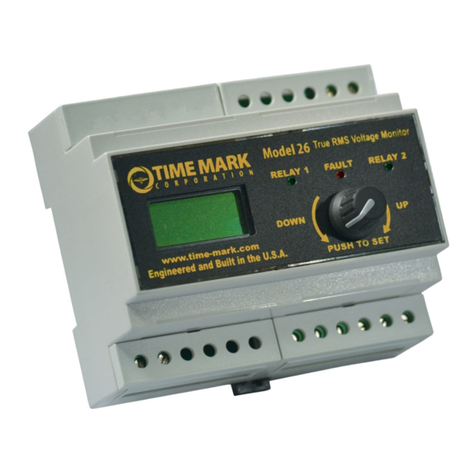
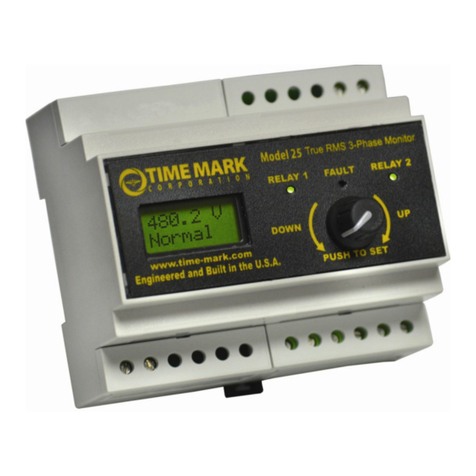
TIME MARK 2629 User manual

SPECIFICATIONS
Model 2629
Supply Voltage 15 to 260 VAC or VDC
Max Supply Voltage 280 VAC or 300 VDC
Power Consumption 1.5 watts max.
Transient Protection 2500 V for 10 msec
Setpoint Stability ± 1%
Response Time 1 sec ON / 100 msec OFF
Reset Type Automatic
Dead Band less than 5% all ranges
Contact Rating DPDT 5A at 240 VAC resistive
Expected Relay Life Mech: 5million operations
Elec: 100,000 at rated load
Operating Temperature -13º to +122º F
Humidity Tolerance 0-97% without condensation
Enclosure Material ABS plastic
Weight 5 oz.
Mounting 8-pin socket (*order separately)
* Order 8-pin socket number 51X120
DESCRIPTION
The Model 2629 AC/DC Voltage Monitor is designed
to continuously monitor any AC or DC voltage from 15
to 260 volts.
Input voltages above the setpoint cause the output
contacts to energize. Input voltages below the setpoint
cause the output contacts to de-energize. The dead
band between pull-in and drop-out is less than 5%.
Dip switches are used on the Model 2629 to choose
between AC and DC voltage monitoring, and to select
one of the eight trip level ranges. Each trip level has a
user adjustable 35 volt range, with a 5 volt overlap
between the ranges. The unit has a screwdriver
adjustment to set the trip point within that 35 volt range.
ll Monitors Over or Under Voltage
ll AC or DC from 15 to 260 Volts
ll Adjustable Trip Points
ll Automatic Reset
ll DPDT Relay
MODEL 2629
AC/DC
Voltage Monitor
TIME MARK is a division of
Telephone: Main -(918) 438-1220
Sales -(800) 862-2875
Fax: (918) 437-7584
E-mail: sales@time-mark.com
Internet:http://www.time-mark.com
11440 East Pine Street
Tulsa, Oklahoma 74116
DIMENSIONS
01/02
TYPICAL APPLICATION

ADJUSTMENT PROCEDURE
Select the range where the desired trip voltage falls in
between the choices shown on the chart shown below. The
same Range Chart is also screened on the unit.
Set the dial to the difference between the desired voltage and
the low number selected.
TROUBLESHOOTING
Should the Model 2629AC/DC Voltage Monitor fail to operate,
check all connections. Verify that the proper voltage is
present, and check all fuses. Should problems persist,
contact the factory at 800-862-2875, for assistance (Monday
thru Friday, 8 a.m. to 5 p.m. CST).
WARRANTY
The Model 2629AC/DC Voltage Monitor is warranted to be
free from defects in materials and workmanship, and is
covered by our exclusive 5-year Unconditional Warranty. If
this device fails to operate, for any reason, we will repair or
replace it, free, for five years from the date of purchase.
Contact the Time Mark Sales department, Monday through
Friday; 8 a.m. to 5 p.m., CST, for further details.
INSTALLATION
Connect the voltage to be monitored to the socket using
the Pin Diagram pictured on this data sheet and on the
unit as a reference (contacts are shown in the de-
energized condition).
The output contacts used will depend on whether the
Model 2629 is used to detect over-voltage or under-
voltage, and whether the unit will shut off a load, or trip
an alarm.
The monitor’s internal relay will energize when the input
voltage is above the trip level setting. This allows the
unit to be set to detect over-voltage (relay will energize
on fault). The LED indicator will illuminate whenever
the relay is energized.
NOTE: When installing the Model 2629 Voltage Monitor in
areas of high humidity or contamination, it is recommended that
the base area and all exposed metal parts of the socket be coated
liberally with a good quality silicon grease, such as Dow Corning
DC-4 or DC-4X. Insert the unit into the socket and wipe off
excess grease around the base. This will prevent the entrance of
moisture and other contaminates into the base and socket areas.
PIN DIAGRAM
WARNING
THE MODEL 2629IS NOT TO BE USED IN
APPLICATIONS WHERE VOLTAGES
IN EXCESS OF 300 VAC
ARE TO BE MONITORED OR SWITCHED.
POWER
0
510 15 20 25
30
35
RELAY ENERGIZED
ON
OFF
—OPEN—
1 2 3 4
LED Indicator
Dip Switch
Dial adjustment
SWITCHES SWITCH
1 2 3 RANGE 4
0 0 0 15 -50 ON=DC
1 0 0 45 -80 OFF=AC
0 1 0 75 -110
1 1 0 105 -140
0 0 1 135 -170
1 0 1 165 -200
0 1 1 195 -230
1 1 1 225 -260
0=OFF 1= ON
MODEL 2629
AC/DC Voltage Monitor
READ ALL INSTRUCTIONS BEFORE INSTALLING, OPERATING OR SERVICING THIS DEVICE.
KEEP THIS DATA SHEET FOR FUTURE REFERENCE.
GENERAL SAFETY
POTENTIALLY HAZARDOUS VOLTAGES ARE PRESENT AT THE TERMINALS OF THE MODEL 2629.
ALL ELECTRICAL POWER SHOULD BE REMOVED WHEN CONNECTING OR DISCONNECTING WIRING.
THIS DEVICE SHOULD BE INSTALLED AND SERVICED BY QUALIFIED PERSONNEL.
Installation Instructions
TIME MARK is a division of
Telephone: Main -(918) 438-1220
Sales -(800) 862-2875
Fax: (918) 437-7584
E-mail: sales@time-mark.com
Internet:http://www.time-mark.com
11440 East Pine Street
Tulsa, Oklahoma 74116
01/02

ORDERING STANDARD MODELS:
AUTOMATIC RESET
AC DC
AC260B-80-130 DC260B-20-24
AC260B-160-250 DC260B-30-46
AC260B-215-290 DC260B-42-64
AC260B-380-480 DC260B-60-92
DC260B-90-150
DC260B-160-250
MANUAL RESET
AC DC
AC260BM-80-130 DC260BM-20-24
AC260BM-160-250 DC260BM-30-46
AC260BM-215-290 DC260BM-42-64
AC260BM-380-480 DC260BM-60-92
DC260BM-90-150
DC260BM-160-250
DESCRIPTION
The Model 260 Voltage Sensor is a single setpoint voltage
sensor. Input voltages above the setpoint cause the output
contacts to energize (contacts 1 & 8 closed). Input voltages
below the setpoint cause the output contacts to de-energize
(contacts 1 & 2 closed). The dead band between pull-in and
drop-out is less than 2%.
The standard unit has a screwdriver, or fingertip adjustable
setpoint range of approximately 35% of the maximum
voltage. This device can also be provided with a factory
calibrated trip point.
AC versions of the Model 260 Voltage Sensor are not
frequency sensitive, and may be used in systems from 50Hz
to 400 Hz. DC models are not polarity sensitive.
This device requires a standard 8-pin socket, such as Time
Mark’s Model 51X120.
SPECIFICATIONS
MODEL 260
Input voltage see Ordering Info tables
Transient protection 2500 VRMS for 10 msecs
Polarity protection not required
Supply current 10mA max.
Setpoint stability ± 1%
Response time 100 msecs
Operation Continuous duty
Output contacts SPDT 10 Amps at 240 VAC resistive
Expected relay life
Mech: 10 million operations
Elec: 100,000 operations at rated load
Operating temperature -40º to +131º F
Humidity tolerance 0-97% without condensation
Enclosure material ABS plastic
Mounting 8-pin socket (**order separately)
Weight 5 oz.
Agency approval All AC & DC Auto Reset versions:
UL Recognized*and CSA Certified*
* condition of acceptability:
All units receiving input voltages of 300 volts or
more must use a UL Recognized 600V socket.
**order 8-pin socket number 51X120
ORDERING NON-STANDARD VERSIONS:
Voltage Model Adjustment Reset Setpoint
or Range
DC 260 A=factory calibrated M=manual reset xxx or
AC B=screwdriver adjust or auto reset xxx-xxx
is assumed
example: AC260 AM 230
orders an AC voltage sensor with manual reset, factory calibrated to trip at 230vac
ll Monitors for Over or Under Voltage
ll LED status indicator
ll Plug-in Mounting
ll Automatic Reset
ll 5 Year Unconditional Warranty
MODEL 260
Voltage Sensor
TIME MARK is a division of
Telephone: Main -(918) 438-1220
Sales -(800) 862-2875
Fax: (918) 437-7584
E-mail: sales@time-mark.com
Internet:http://www.time-mark.com
Doc No. 87A133 12/00
© 2000 TIME MARK CORPORATION
11440 East Pine Street
Tulsa, Oklahoma 74116

1.95"
DIMENSIONS
INSTALLATION
Mount the unit in a suitable enclosure. A NEMA-1 enclosure, designed
for socket-mounted relays is available from Time Mark.
Connect the voltage to be monitored to terminals 6 and 7. These termi-
nals are not polarity sensitive for any of the listed AC or DC models.
Connect the load control wiring to the appropriate terminals on the
socket:
For motor control applications; use terminals 1 and 8.
For phase loss alarm applications; use terminals 1 and 2.
Insert the Model 260 into the socket and apply power. If the contact
does not transfer (green light ON), use a voltmeter to insure that the
proper voltage is present. If voltage is correct, rotate the level
adjustment fully counter-clockwise. The contact should transfer to
provide a signal path between pins 1 and 8.
NOTE: When installing the Model 260 Sensor in areas of high humidity
or contamination, it is recommended that the base area and all
exposed metal parts of the socket be coated liberally with a good
quality silicon grease, such as Dow Corning DC-4 or DC-4X. Insert the
unit into the socket and wipe off excess grease around the base. This
will prevent the entrance of moisture and other contaminates into the
base and socket areas.
ADJUSTMENT PROCEDURE
The following procedure will allow the Model 260 Voltage Sensor to be
adjusted to achieve a trip point just below the nominal voltage being
monitored.
Rotate the adjustment control fully clockwise, or until the red (TRIP)
indicator illuminates.
On manual reset versions, it will be necessary to hold the reset button
down during this next step:
Slowly rotate the adjustment control in a counter-clockwise direction,
just until the green (NORM) indicator comes on.
WARNING
IN APPLICATIONS WHERE VOLTAGES IN EXCESS OF 300
VAC ARE TO BE MONITORED, BE CERTAIN TO USE THE
TIME MARK MODEL 51X120 8-PIN SOCKET, OR AN
EQUIVALENT UL APPROVED 600VAC RATED SOCKET.
MODEL 260 Voltage Sensor
READ ALL INSTRUCTIONS BEFORE INSTALLING, OPERATING OR SERVICING THIS DEVICE.
KEEP THIS DATA SHEET FOR FUTURE REFERENCE.
GENERAL SAFETY
POTENTIALLY HAZARDOUS VOLTAGES ARE PRESENT AT THE TERMINALS OF THE MODEL 260.
ALL ELECTRICAL POWER SHOULD BE REMOVED WHEN CONNECTING OR DISCONNECTING WIRING.
THIS DEVICE SHOULD BE INSTALLED AND SERVICED BY QUALIFIED PERSONNEL.
Installation Instructions
At this point, the Model 260 Voltage Sensor is the most sensitive to
irregular power line conditions. If nuisance tripping occurs, turn the
control slightly farther counter-clockwise.
A more accurate setting will require the use of an adjustable voltage
source, and a voltmeter to achieve an exact setting.
TROUBLESHOOTING
Should the Model 260 Voltage Sensor fail to operate properly, check
that proper voltage is being applied to pins 6 and 7. On manual
reset versions, place a jumper across pins 3 and 4 if an external,
normally-closed reset switch is not connected. Should problems
persist, contact your local Time Mark Distributor, or the factory at
800-862-2875 (Monday-Friday; 8 a.m. to 5 p.m. CST), for further
assistance.
WARRANTY
The Model 260 Voltage Sensor is warranted to be free from defects
in materials and workmanship, and is covered by our exclusive 5-
year Unconditional Warranty. If the Model 260 fails to operate, for
any reason, we will repair or replace it free, for five years from the
date of purchase. Contact the Time Mark Sales department, Monday
through Friday; 8 a.m. to 5 p.m., CST, for further details.
12 3 4
5
6
7
8
Shows contacts in power off condition
PIN DIAGRAM
TIME MARK is a division of
Telephone: Main -(918) 438-1220
Sales -(800) 862-2875
Fax: (918) 437-7584
E-mail: sales@time-mark.com
Internet:http://www.time-mark.com
Doc No. 87A133 12/00
© 2000 TIME MARK CORPORATION
11440 East Pine Street
Tulsa, Oklahoma 74116
TYPICAL APPLICATION
Shows No Power Applied

DESCRIPTION
The Model 2601 Voltage Sensor is a single-setpoint
under voltage monitor. Input voltages above the
setpoint will cause the output contact to energize and
the LED indicator to illuminate. Input voltages below the
setpoint will cause the output contact to de-energize
and the LED indicator will go off.
The 2601 Voltage Sensor is available in AC or DC
versions. AC models of the 2601 are not frequency
sensitive and can be used on systems from 50 to 400
Hz. The voltage level is screwdriver adjustable over a
wide operating range.
This device requires a standard 8-pin socket for
mounting (see Model 51X120 under Accessories in the
Time Mark catalog).
DIMENSIONS
ll Monitors Under Voltage
ll SPDT Output
ll Automatic Reset
ll 5 Year Unconditional Warranty
MODEL 2601
Voltage Sensor
TIME MARK is a division of
Telephone: Main -(918) 438-1220
Sales -(800) 862-2875
Fax: (918) 437-7584
E-mail: sales@time-mark.com
Internet:http://www.time-mark.com
Doc No. 87A167 12/00
© 2000 TIME MARK CORPORATION
11440 East Pine Street
Tulsa, Oklahoma 74116
SPECIFICATIONS
2601 -AC VERSIONS
Nominal AC Voltages 24VAC 120VAC 208VAC 240VAC
Voltage Range 19 -24 90 -120 185 -200 200 -240
Max. Input Voltage 32V 160V 250V 285V
Input Frequency (Hz) 50 -400 50 -400 50 -400
2601 -DC VERSIONS
Nominal DC Voltage 12VDC 24VDC 28VDC 48VDC 110VDC
Voltage Range 10 -12 19 -24 22 -28 33 -48 85 -100
Max. Input Voltage 17V 32V 37V 62V 145V
2601 -ALL VERSIONS
Power Consumption 2 W max.
Setpoint Stability ± 0.5% of setpoint
Dead Band 2%
Polarity Protection DC versions only
Trip Response 0.5 second fixed (± 0.1 second)
Reset Time 0.1 second
Output Contacts SPDT 10A at 240VAC resistive
Expected Relay Life Mech: 10 million operations
Elec: 100,000 at rated load
Operating Temp -40º to +122º F
Humidity Tolerance 97% w/o condensation
Mounting 8-pin socket *(order separately)
Enclosure Material ABS plastic
Weight 5 oz.
* Order 8-pin socket number 51X120
50 -400

INSTALLATION
The Model 2601 is a socket-mounted voltage sensing
relay. The pin configuration diagram, below and on the
unit, shows the contacts in the power off or tripped
condition. Connect the wiring to the socket as shown in
the Typical Application Diagram. Observe the proper
polarity of the input voltage for DC models.
PIN DIAGRAM
ADJUSTMENT PROCEDURE
NOTE: When adjusting the Model 2601 you may wish
to jumper the control circuit contacts to prevent tripping
the load on and off. A variable voltage source and a
digital voltmeter provide the most accurate means of
calibrating the trip point.
For under voltage sensing, slowly rotate the
adjustment pot counter clockwise until the indicator
light just illuminates and the contacts transfer. Any
voltage below this level will now trip the relay.
A reasonably accurate voltage setting can be obtained
by using only the operating line voltage. Apply the
voltage and follow the adjustment procedure above.
Any voltage approximately 2% to 4% below the nominal
voltage will now trip the relay. To prevent nuisance
tripping you may need to turn the adjustments slightly
lower as needed.
WARRANTY
The Model 2601 Voltage Sensor is covered by Time
Mark Corporation’s exclusive 5-Year Unconditional
Warranty. Should this device fail, for any reason,
within five years from the date of purchase, we will
repair or replace it free. Contact the Time Mark Sales
department, Monday through Friday; 8 a.m. to 5 p.m.,
CST, for further details.
TYPICAL APPLICATION
4
3
Model 2601
MODEL 2601 Voltage Sensor
READ ALL INSTRUCTIONS BEFORE INSTALLING, OPERATING OR SERVICING THIS DEVICE.
KEEP THIS DATA SHEET FOR FUTURE REFERENCE.
GENERAL SAFETY
POTENTIALLY HAZARDOUS VOLTAGES ARE PRESENT AT THE TERMINALS OF THE MODEL 2601.
ALL ELECTRICAL POWER SHOULD BE REMOVED WHEN CONNECTING OR DISCONNECTING WIRING.
THIS DEVICE SHOULD BE INSTALLED AND SERVICED BY QUALIFIED PERSONNEL.
Installation Instructions
NOTE: When installing the Model 2601 in areas of high
humidity or contamination, the base area and all exposed
metal parts of the socket should be coated with a good
quality silicon grease such as Dow Corning* DC-4 or DC-4x.
Insert the relay into the socket and wipe off excess grease
from around the base. This will help prevent moisture and
other contaminants from entering the base and socket areas.
TIME MARK is a division of
Telephone: Main -(918) 438-1220
Sales -(800) 862-2875
Fax: (918) 437-7584
E-mail: sales@time-mark.com
Internet:http://www.time-mark.com
Doc No. 87A167 12/00
© 2000 TIME MARK CORPORATION
11440 East Pine Street
Tulsa, Oklahoma 74116
Shows No Power Applied

ll Protects voltage-sensitive equipment
ll Reset delay timer
ll Automatic reset
ll DPDT output relay
DESCRIPTION
The Model 2602 Voltage Sensor is a rapid response
device for sensing a low voltage condition on 120 VAC,
60 Hz, single phase power systems. Operating power is
drawn from the same line being monitored.
Upon sensing a voltage below 80 VAC, the internal
relay, which is energized under normal operating
conditions, will drop out.
The solid-state sensor will respond in one-half of an AC
cycle (8.33 msec.), plus the flight time of the relay (20
msec. max.). When the voltage rises above 84 VAC, an
internal 10-second timer begins. When the time delay
elapses the relay will automatically re-energize.
There are no field adjustments or calibrations to the
device.
MODEL 2602
Nominal input voltage 120 VAC
Max. input voltage 135 VAC
Frequency 60 Hz
Power consumption 2 watts max.
Drop-out voltage 80 VAC
Pick-up voltage 84 VAC
Repeat accuracy ± 1% (fixed conditions)
Repeat accuracy ± 2% (0°-140° F)
Output DPDT 10A at 240 VAC resistive
Expected relay life Mechanical: 10 million operations
Electrical: 100,000 oper at rated load
Reset Automatic
Response time 28.3 msec max.
Reset time 10 seconds
Operating temperature -40º to +140º F
Humidity tolerance 0-97% without condensation
Case material ABS plastic
Weight 9.4 oz.
SPECIFICATIONS
DIMENSIONS
3.13"
4.5"
2.25"
4.0"
4.8"
3.5"
MODEL 2602
Voltage Sensor
TIME MARK is a division of
Telephone: Main -(918) 438-1220
Sales -(800) 862-2875
Fax: (918) 437-7584
E-mail: sales@time-mark.com
Internet:http://www.time-mark.com
Doc No. 87A223 12/00
© 2000 TIME MARK CORPORATION
11440 East Pine Street
Tulsa, Oklahoma 74116

INSTALLATION
Connect the control wiring to the terminals with the
contact markings (refer to the diagram on the unit).
Apply power.
ADJUSTMENT
No calibration or adjustments needed for this
device.
WARRANTY
The Model 2602 Voltage Sensor is warranted to
be free from defects in materials and workmanship
for one year. If the Model 2602 fails to operate, for
any reason, we will repair or replace it free, for one
year from the date of purchase. Contact the Time
Mark Sales department, Monday through Friday;
8 a.m. to 5 p.m., CST, for further details.
TYPICAL APPLICATION
MODEL 2602 Voltage Sensor
READ ALL INSTRUCTIONS BEFORE INSTALLING, OPERATING OR SERVICING THIS DEVICE.
KEEP THIS DATA SHEET FOR FUTURE REFERENCE.
GENERAL SAFETY
POTENTIALLY HAZARDOUS VOLTAGES ARE PRESENT AT THE TERMINALS OF THE MODEL 2602.
ALL ELECTRICAL POWER SHOULD BE REMOVED WHEN CONNECTING OR DISCONNECTING WIRING.
THIS DEVICE SHOULD BE INSTALLED AND SERVICED BY QUALIFIED PERSONNEL.
Installation Instructions
TIME MARK is a division of
Telephone: Main -(918) 438-1220
Sales -(800) 862-2875
Fax: (918) 437-7584
E-mail: sales@time-mark.com
Internet:http://www.time-mark.com
Doc No. 87A223 12/00
© 2000 TIME MARK CORPORATION
11440 East Pine Street
Tulsa, Oklahoma 74116
Shows No Power Applied
TROUBLESHOOTING
Should the Model 2602 Voltage Sensor fail to
operate, check all connections. Verify that power
is present, and check all fuses. Should problems
persist, contact the factory at 800-862-2875 for
assistance.

SPECIFICATIONS
Model 2628
Supply Voltage 15 to 260 VAC or VDC
Max Supply Voltage 280 VAC or 300 VDC
Power Consumption 1.5 watts max.
Transient Protection 2500 V for 10 msec
Setpoint Stability ± 1%
Response Time 1 sec ON / 100 msec OFF
Reset Type Automatic
Dead Band less than 5% all ranges
Contact Rating SPDT 10A at 240 VAC resistive
Expected Relay Life Mech: 10 million operations
Elec: 100,000 at rated load
Operating Temperature -13º to +122º F
Humidity Tolerance 0-97% without condensation
Enclosure Material ABS plastic
Weight 5 oz.
Mounting 8-pin socket (*order separately)
* Order 8-pin socket number 51X120
DESCRIPTION
The Model 2628 AC/DC Voltage Monitor is designed
to continuously monitor any AC or DC voltage from 15
to 260 volts.
Input voltages above the setpoint cause the output
contacts to energize. Input voltages below the setpoint
cause the output contacts to de-energize. The dead
band between pull-in and drop-out is less than 5%.
Dip switches are used on the Model 2628 to choose
between AC and DC voltage monitoring, and to select
one of the eight trip level ranges. Each trip level has a
35 volt range, with a 5 volt overlap between the ranges.
The unit has a screwdriver adjustment to set the exact
trip point within that 35 volt range.
TYPICAL APPLICATION
Start
Stop
M
MMotor
M
62
8
7 1
L1
L2
Model 2628
Control
voltage
Sensing
Circuit
O/L's
M
DIMENSIONS
ll Monitors Over or Under Voltage
ll AC or DC from 15 to 260 Volts
ll Adjustable Trip Points
ll Automatic Reset
MODEL 2628
AC/DC
Voltage Monitor
TIME MARK is a division of
Telephone: Main -(918) 438-1220
Sales -(800) 862-2875
Fax: (918) 437-7584
E-mail: sales@time-mark.com
Internet:http://www.time-mark.com
Doc No. 87A395 12/00
© 2000 TIME MARK CORPORATION
11440 East Pine Street
Tulsa, Oklahoma 74116
Shows No Power Applied

ADJUSTMENT PROCEDURE
Select the range where the desired trip voltage falls in
between the choices shown on the chart shown below. The
same Range Chart is also screened on the unit.
Set the dial to the difference between the desired voltage and
the low number selected.
TROUBLESHOOTING
Should the Model 2628 AC/DC Voltage Monitor fail to operate,
check all connections. Verify that the proper voltage is
present, and check all fuses. Should problems persist,
contact the factory at 800-862-2875, for assistance (Monday
thru Friday, 8 a.m. to 5 p.m. CST).
WARRANTY
The Model 2628 AC/DC Voltage Monitor is warranted to be
free from defects in materials and workmanship, and is
covered by our exclusive 5-year Unconditional Warranty. If
this device fails to operate, for any reason, we will repair or
replace it, free, for five years from the date of purchase.
Contact the Time Mark Sales department, Monday through
Friday; 8 a.m. to 5 p.m., CST, for further details.
INSTALLATION
Connect the voltage to be monitored to the socket using
the Pin Diagram pictured on this data sheet and on the
unit as a reference (contacts are shown in the de-
energized condition).
The output contacts used will depend on whether the
Model 2628 is used to detect over-voltage or under-
voltage, and whether the unit will shut off a load, or trip
an alarm.
The monitor’s internal relay will energize when the input
voltage is above the trip level setting. This allows the
unit to be set to detect over-voltage (relay will energize
on fault). The LED indicator will illuminate whenever
the relay is energized.
NOTE: When installing the Model 2628 Voltage Monitor in
areas of high humidity or contamination, it is recommended that
the base area and all exposed metal parts of the socket be coated
liberally with a good quality silicon grease, such as Dow Corning
DC-4 or DC-4X. Insert the unit into the socket and wipe off
excess grease around the base. This will prevent the entrance of
moisture and other contaminates into the base and socket areas.
PIN DIAGRAM
WARNING
THE MODEL 2628 IS NOT TO BE USED IN
APPLICATIONS WHERE VOLTAGES
IN EXCESS OF 300 VAC
ARE TO BE MONITORED OR SWITCHED.
POWER
4
5
6
7
8
1
23
0
5
10 15 20 2530
35
RELAY ENERGIZED
ON
OFF
—OPEN—
1234
LED Indicator
Dip Switch
Dial adjustment
SWITCHES SWITCH
1 2 3 RANGE 4
0 0 0 15 -50 ON=DC
1 0 0 45 -80 OFF=AC
0 1 0 75 -110
1 1 0 105 -140
0 0 1 135 -170
1 0 1 165 -200
0 1 1 195 -230
1 1 1 225 -260
0=OFF 1= ON
MODEL 2628
AC/DC Voltage Monitor
READ ALL INSTRUCTIONS BEFORE INSTALLING, OPERATING OR SERVICING THIS DEVICE.
KEEP THIS DATA SHEET FOR FUTURE REFERENCE.
GENERAL SAFETY
POTENTIALLY HAZARDOUS VOLTAGES ARE PRESENT AT THE TERMINALS OF THE MODEL 2628.
ALL ELECTRICAL POWER SHOULD BE REMOVED WHEN CONNECTING OR DISCONNECTING WIRING.
THIS DEVICE SHOULD BE INSTALLED AND SERVICED BY QUALIFIED PERSONNEL.
Installation Instructions
TIME MARK is a division of
Telephone: Main -(918) 438-1220
Sales -(800) 862-2875
Fax: (918) 437-7584
E-mail: sales@time-mark.com
Internet:http://www.time-mark.com
Doc No. 87A395 12/00
© 2000 TIME MARK CORPORATION
11440 East Pine Street
Tulsa, Oklahoma 74116
Shown De-Energized

DIMENSIONS
1.95"
DESCRIPTION
The Model 268 Over & Under Voltage Monitor is
designed to insure that the monitored operating voltage
remains within a 120 VAC band. This device uses a
dual op-amp comparator circuit to achieve stable and
repeatable trip setpoints.
The output relay is energized only when the voltage
being monitored remains between the upper and lower
setpoints. Voltages above or below the setpoints will
de-energize the relay, and illuminate the appropriate
indicator LED.
The Model 268 Over & Under Voltage Monitor is
designed for continuous duty operation.
SPECIFICATIONS
Model 268
Setpoint stability
Fixed conditions: 0.1% max
Over temp range: 1.2% max
Adjustment range
Over voltage: 120 -140 VAC
Under voltage: 90 -110 VAC
Response time 50 msec
Line frequency 45 -420 Hz
Transient protection 2500V for 10 msec
Contacts SPDT
Contact rating 10A at 240 VAC resistive
Operating temperature -40º to +130º F
Humidity tolerance 0-97% without condensation
Enclosure material ABS plastic
Mounting 8-pin socket (*order separately)
Weight 4 oz.
*order 8-pin socket number 51X120
ll Both high & low trip point adjustments
ll Monitors over and under voltage
ll Useful range of 90 to 140 VAC
ll Automatic reset
MODEL 268
Over/Under
Voltage Monitor
TIME MARK is a division of
Telephone: Main -(918) 438-1220
Sales -(800) 862-2875
Fax: (918) 437-7584
E-mail: sales@time-mark.com
Internet:http://www.time-mark.com
Doc No. 87A134 12/00
© 2000 TIME MARK CORPORATION
11440 East Pine Street
Tulsa, Oklahoma 74116
PIN DRAWING
12 3 4
5
6
7
8
115 VAC
Shown De-Energized

INSTALLATION
The Model 268 Over and Under Voltage Monitor is a voltage
sensing relay. The relay requires an 8-pin mounting socket, such as
Time Mark’s Model 51X120. The base connecting diagram on the
unit shows the contacts in the ‘power off‘ condition. The markings on
the unit show the proper voltage and adjustment range of the device
to be installed.
Connect the wiring to socket, as required (see the Typical
Application diagram).
ADJUSTMENT PROCEDURE
A variable voltage source and a digital voltmeter provide the most
accurate means of calibrating the trip point setting. However, for AC
line voltages, you can often obtain a satisfactory calibration by using
only the AC line voltage.
Rotate the UNDER VOLTAGE adjustment pot clockwise, until the
relay trips, and the UNDER VOLTAGE LED indicator is lit.
Then, rotate the adjustment pot counter-clockwise slowly, until the
relay resets. The UNDER VOLTAGE LED should be off.
Rotate the OVER VOLTAGE adjustment pot counter-clock-wise,
until the relay trips, and the OVER VOLTAGE LED indicator is lit.
Then, rotate the adjustment pot clockwise slowly, until the relay
resets. The OVER VOLTAGE LED should now be off.
TROUBLESHOOTING
Should the Model 268 Over and Under Voltage Monitor fail to
operate properly, check all wiring connections. Verify that the
correct voltage is present, and check all fuses. Should problems
persist, contact your local Time Mark distributor, or the factory at
800-862-2875 (Monday-Friday; 8 a.m. to 5 p.m. CST), for further
assistance.
WARRANTY
The Model 268 Over & Under Voltage Monitor is warranted to
be free from defects in materials and workmanship, and is
covered by our exclusive 5-year Unconditional Warranty. If
this device fails to operate, for any reason, we will repair or
replace it, free, for five years from the date of purchase. Contact
the Time Mark Sales department, Monday through Friday; 8 a.m.
to 5 p.m., CST, for further details.
TYPICAL APPLICATION
Shows No Power
Applied
MODEL 268 Over/Under Voltage Monitor
READ ALL INSTRUCTIONS BEFORE INSTALLING, OPERATING OR SERVICING THIS DEVICE.
KEEP THIS DATA SHEET FOR FUTURE REFERENCE.
GENERAL SAFETY
POTENTIALLY HAZARDOUS VOLTAGES ARE PRESENT AT THE TERMINALS OF THE MODEL 268.
ALL ELECTRICAL POWER SHOULD BE REMOVED WHEN CONNECTING OR DISCONNECTING WIRING.
THIS DEVICE SHOULD BE INSTALLED AND SERVICED BY QUALIFIED PERSONNEL.
Installation Instructions
TIME MARK is a division of
Telephone: Main -(918) 438-1220
Sales -(800) 862-2875
Fax: (918) 437-7584
E-mail: sales@time-mark.com
Internet:http://www.time-mark.com
Doc No. 87A134 12/00
© 2000 TIME MARK CORPORATION
11440 East Pine Street
Tulsa, Oklahoma 74116
These calibrations will be correct in most applications. If
nuisance tripping occurs, turn the adjustments for a slightly
wider voltage band.
NOTE: When installing the Model 268 Voltage Monitor in areas
of high humidity or contamination, it is recommended that the base
area and all exposed metal parts of the socket be coated liberally
with a good quality silicon grease, such as Dow Corning DC-4 or
DC-4X. Insert the unit into the socket and wipe off excess grease
around the base. This will prevent the entrance of moisture and
other contaminates into the base and socket areas.

DESCRIPTION
The Model 2681 Voltage Band Monitor is a dual set-point
voltage monitor. Input voltages between the upper and lower
set-points will cause the output contacts to pull in (contacts 1
& 3 closed) and the LED indicator to illuminate. Input
voltages above or below the set-points will cause the output
contacts to drop out (contacts 1 & 4 closed) and extinguish
the LED indicator.
The Model 2681 is available in AC or DC versions. AC
models of the 2681 are not frequency sensitive and can be
used on systems from 50 to 400 Hz. The voltage set-points
are screwdriver adjustable over a wide operating range.
The SPDT ouput configuration is identical to the configuration
of general purpose relays. This unit requires a standard 8-
pin socket for mounting.
SPECIFICATIONS
2681 -AC VERSIONS
Nominal AC voltages 24vac 120vac 208vac 240vac
Max input voltage 32vac 160vac 250vac 285vac
Under voltage range 19-24vac 90-120vac 185-208vac 200-240vac
Over voltage range 24-29vac 120-150vac 240-270vac
Input frequency (Hz) 50 -400 Hz
2681 -DC VERSIONS
Nominal DC Voltage 12vdc 24vdc 28vdc 48vdc 110vdc 230vdc
Max input voltage 17vdc 32vdc 37vdc 62vdc 145vdc 270vdc
Under voltage range 10-12vdc 19-24vdc 22-28vdc 38-48vdc 85-110vdc 175-230vdc
Over voltage range 12-15vdc 24-29vdc 28-34vdc 48-58vdc 110-135vdc 230-260vdc
2681 -ALL VERSIONS
Power consumption ± 2 watts max
Set-point stability ± 0.5% of set-point
Dead band 2%
Polarity protection DC versions only
Trip response 0.5 sec fixed (± 0.1 sec)
Reset time 0.1 sec
Output contacts SPDT
Contact rating 10A at 240vac resistive
Expected relay life Mechanical: 10 million operations
Electrical: 100,000 at rated load
Operating temp -40° to +122°F
Humidity tolerance 97% w/o condensation
Mounting 8-pin socket (*order separately)
Case material ABS plastic
Weight 5 oz.
* Order 8-pin socket number 51X120
208-240vac
DIMENSIONS
ll SPDT Output in Standard Relay
Configuration
ll Monitors Over and Under Voltage
ll AC or DC Versions
ll Automatic Reset
MODEL 2681
Voltage Band Monitor
PIN DRAWING
12
3
4
5
6
78
INPUT
TIME MARK is a division of
Telephone: Main -(918) 438-1220
Sales -(800) 862-2875
Fax: (918) 437-7584
E-mail: sales@time-mark.com
Internet:http://www.time-mark.com
Doc No. 87A168 12/00
© 2000 TIME MARK CORPORATION
11440 East Pine Street
Tulsa, Oklahoma 74116
Shown De-Energized

INSTALLATION
The Model 2681 is a socket-mounted voltage band monitor.
The pin configuration diagram on the unit shows the contacts
in the power OFF, or tripped condition.
Connect the wiring to the socket as shown in the Typical
Application diagram. Observe the proper polarity of the
input voltage for DC models.
ADJUSTMENT PROCEDURE
NOTE:
When adjusting the Model 2681 you may wish to jumper the
control circuit contacts to prevent tripping the load on and off.
A variable voltage source and a digital voltmeter provide the
most accurate means of calibrating the trip point setting.
However, for AC line voltages, you can often obtain a satis-
factory calibration by using only the AC line voltage.
Rotate the UNDER VOLTAGE adjustment pot clockwise, until
the relay trips, and the UNDER VOLTAGE LED indicator is lit.
Then, rotate the adjustment pot counter-clockwise slowly,
until the relay resets. The UNDER VOLTAGE LED should be
off.
Rotate the OVER VOLTAGE adjustment pot counter-
clockwise, until the relay trips, and the OVER VOLTAGE LED
indicator is lit.
Then, rotate the adjustment pot clockwise slowly, until the
relay resets. The OVER VOLTAGE LED should now be off.
The above calibrations will be correct in most applications. If
nuisance tripping occurs, turn the adjustments for a slightly
wider voltage band.
A reasonably accurate voltage setting can be obtained by
using only the operating line voltage. Apply the voltage and
follow steps 2 and 4 above.
Voltages approximately 2% to 4% above and below the
nominal voltage will now trip the relay. To prevent nuisance
tripping you may need to turn the adjustments slightly lower
and higher as needed.
TROUBLESHOOTING
Should the Model 2681 fail to operate properly, check that
voltage is present and is of the correct level. Check all
fuses, and verify that all wiring connections are correct.
Should problems persist, contact your local Time Mark
Distributor, or the factory at 800-862-2875 (Monday-
Friday; 8 a.m. to 5 p.m.CST), for further assistance.
WARRANTY
The Model 2681 Voltage Band Monitor is warranted to
be free from defects in materials and workmanship, and is
covered by our exclusive 5-year Unconditional
Warranty. If this device fails to operate, for any reason,
we will repair or replace it free, for five years from the date
of purchase. Contact the Time Mark Sales Department for
further details.
NOTE: When installing the Model 2681 monitor in areas of
high humidity or contamination, it is recommended that the
base area and all exposed metal parts of the socket be
coated liberally with a good quality silicon grease, such as
Dow Corning DC-4 or DC-4X. Insert the unit into the socket
and wipe off excess grease around the base. This will prevent
the entrance of moisture and other contaminates into the
base and socket areas.
TYPICAL APPLICATION
MODEL 2681 Voltage Band Monitor
READ ALL INSTRUCTIONS BEFORE INSTALLING, OPERATING OR SERVICING THIS DEVICE.
KEEP THIS DATA SHEET FOR FUTURE REFERENCE.
GENERAL SAFETY
POTENTIALLY HAZARDOUS VOLTAGES ARE PRESENT AT THE TERMINALS OF THE MODEL 2681 MONITORS.
ALL ELECTRICAL POWER SHOULD BE REMOVED WHEN CONNECTING OR DISCONNECTING WIRING.
THIS DEVICE SHOULD BE INSTALLED AND SERVICED BY QUALIFIED PERSONNEL.
Installation Instructions
TIME MARK is a division of
Telephone: Main -(918) 438-1220
Sales -(800) 862-2875
Fax: (918) 437-7584
E-mail: sales@time-mark.com
Internet:http://www.time-mark.com
Doc No. 87A168 12/00
© 2000 TIME MARK CORPORATION
11440 East Pine Street
Tulsa, Oklahoma 74116
Shows No Power Applied

DIMENSIONS
MODEL 292
Frequency Monitor
SPECIFICATIONS
Model A292 B292 C292
Nominal AC Voltages 24 VAC 120 VAC 230 VAC
Voltage Range 20-30 VAC 90-130 VAC 190-240 VAC
Operating Frequency 45-1023 Hz
Response Time 1 second
Transient Protection 2500 V for 10 msec
Contact Rating SPDT 10 amps at 240VAC resistive
Expected Relay Life Mech: 10 million operations
Elec: 100,000 at rated load
Operating Temp -40° to +122° F
Humidity Tolerance 0-97% w/o condensation
Enclosure Material ABS plastic
Weight 12 oz. Max.
DESCRIPTION
The Model 292 Frequency Monitor is designed to
monitor power line frequency. It is intended for systems
where line frequency variations will cause improper op-
eration of electrical equipment.
A solid-state sensing circuit drives an internal electro-
mechanical relay which is energized when the line fre-
quency is correct. Operating power is drawn from the
same line being monitored.
The Model 292 is set to the over and/or under frequency
trip points using ten binary-coded switches. A fre-
quency variation outside the trip point(s) causes the in-
ternal relay to drop out and an appropriate L E D indica-
tor to illuminate.
Applications for the Model 292 include stand by power
plants, portable power supplies, and windmill genera-
tors.
ll Monitors over and/or under frequency
ll Automatic reset
ll Solid-state electronic circuitry
TIME MARK is a division of
Telephone: Main -(918) 438-1220
Sales -(800) 862-2875
Fax: (918) 437-7584
E-mail: sales@time-mark.com
Internet:http://www.time-mark.com
Doc No. 87A083 12/00
© 2000 TIME MARK CORPORATION
11440 East Pine Street
Tulsa, Oklahoma 74116
.1875” dia. typ.
6.06"
5.5"5.5"
3.88"
3.0"
2.08".62"
Model 292

INSTALLATION
Connect the control wiring to the terminals with the con-
tact markings (refer to the diagram on the unit). Apply
power.
TROUBLESHOOTING
Should the Model 292 Frequency Monitor fail to oper-
ate, check all connections. Verify that power is pre-
sent, and check all fuses. Should problems persist,
contact the factory at 800-862-2875 for assistance.
OPERATION
To select afrequency trip point, set the appropriate
switches to ON. Figure 1 shows the Model 292 set to
trip at frequencies below 58 Hz and above 62 Hz.
Figure 2 shows the Model 292 set for a frequency band
of 400 Hz +/-5 Hz.
WARRANTY
The Model 292 Frequency Monitor is warranted to be
free from defects in materials and workmanship for one
year. Should this device fail to operate, we will repair
or replace it for one year from the date of purchase.
For complete warranty details, see the Terms and Con-
ditions of Sales page in the front section of the Time
Mark catalog.
MODEL 292 Frequency Monitor
READ ALL INSTRUCTIONS BEFORE INSTALLING, OPERATING OR SERVICING THIS DEVICE.
KEEP THIS DATA SHEET FOR FUTURE REFERENCE.
GENERAL SAFETY
POTENTIALLY HAZARDOUS VOLTAGES ARE PRESENT AT THE TERMINALS OF THE MODEL 292.
ALL ELECTRICAL POWER SHOULD BE REMOVED WHEN CONNECTING OR DISCONNECTING WIRING.
THIS DEVICE SHOULD BE INSTALLED AND SERVICED BY QUALIFIED PERSONNEL.
Installation Instructions
TIME MARK is a division of
Telephone: Main -(918) 438-1220
Sales -(800) 862-2875
Fax: (918) 437-7584
E-mail: sales@time-mark.com
Internet:http://www.time-mark.com
Doc No. 87A083 12/00
© 2000 TIME MARK CORPORATION
11440 East Pine Street
Tulsa, Oklahoma 74116
1
2
4
8
16
32
64
128
256
512
1
2
4
8
16
32
64
128
256
512
HI
LO
Switch ON
Switch OFF
1
2
4
8
16
32
64
128
256
512
1
2
4
8
16
32
64
128
256
512
HI
LO
Switch ON
Switch OFF
Figure 1
Figure 2
Model
292
M
TYPICAL APPLICATION
Shows No Power Applied

DESCRIPTION
The Model 2962 Voltage/Frequency Monitor is
designed to monitor frequency, phase sequence and
voltage. Before the relay will energize, phase sequence
must be correct (A B C). Both the frequency and
voltage must also be above the pickup setting before
the relay will energize. If reverse phasing occurs, or if
the frequency or voltage drop below the drop out
setting, the relay will de-energize.
Four red LEDs are used to indicate whether the voltage
or frequency are above or below their set points. A
green LED indicates the condition of relay.
This device is powered by an external 24VDC supply. A
typical application is to monitor engine-powered
generators.
SPECIFICATIONS
MODEL 2962
Input Voltage 24VDC ±10%
Input Current 63 mA max. fused
Power Consumption 0.36W
Monitoring Voltage 120V 3-phase
Monitoring Current 1 mA max. 120V per phase
Voltage Adjustment Range 79 -140VAC drop out & pick up
Frequency Adjustment Range 45 -65 Hz
Reset Type Automatic
Repeat Accuracy ±1% of full scale
Output Contacts SPDT 10 amps at 240VAC resistive
Expected Relay Life Mech: 10 million operations
Elec: 100,000 operations at rated load
Operating Temperature -40° to +131° F
Humidity Tolerance 0 -97% w/o condensation
Enclosure Material ABS plastic
Mounting Surface
Weight 11 oz.
ll Monitors Voltage, Frequency
and Phase Sequence
ll 24V DC Input Voltage
ll For Engine-Powered Generators
ll 5 Year Unconditional Warranty
MODEL 2962
Voltage/Frequency
Monitor
DIMENSIONS
C
L
3.88"
3.0"
0.44"
3.03" Holes are symetrical
about center line.
0.203" 4 PL.
5.5" 6.06" 0.55"
2.63"
0.28"
TIME MARK is a division of
Telephone: Main -(918) 438-1220
Sales -(800) 862-2875
Fax: (918) 437-7584
E-mail: sales@time-mark.com
Internet:http://www.time-mark.com
Doc No. 87A460 12/00
© 2000 TIME MARK CORPORATION
11440 East Pine Street
Tulsa, Oklahoma 74116

WARRANTY
The Model 2962 Voltage/Frequency Monitor is
warranted to be free from defects in materials and
workmanship, and is covered by our exclusive 5-year
Unconditional Warranty. If this device fails to
operate, for any reason, we will repair or replace it free,
for five years from the date of purchase. Contact the
Time Mark Sales department, Monday through Friday; 8
a.m. to 5 p.m., CST for further details.
MODEL 2962 Voltage/Frequency Monitor
READ ALL INSTRUCTIONS BEFORE INSTALLING, OPERATING OR SERVICING THIS DEVICE.
KEEP THIS DATA SHEET FOR FUTURE REFERENCE.
GENERAL SAFETY
POTENTIALLY HAZARDOUS VOLTAGES ARE PRESENT AT THE TERMINALS OF THE MODEL 2962.
ALL ELECTRICAL POWER SHOULD BE REMOVED WHEN CONNECTING OR DISCONNECTING WIRING.
THIS DEVICE SHOULD BE INSTALLED AND SERVICED BY QUALIFIED PERSONNEL.
Installation Instructions
TIME MARK is a division of
Telephone: Main -(918) 438-1220
Sales -(800) 862-2875
Fax: (918) 437-7584
E-mail: sales@time-mark.com
Internet:http://www.time-mark.com
Doc No. 87A460 12/00
© 2000 TIME MARK CORPORATION
11440 East Pine Street
Tulsa, Oklahoma 74116
INSTALLATION
Connect the 3-phase wiring to the terminals marked A,
Band C. Connect 24VDC to marked terminals.
Connect the control wires to the terminals with the relay
contact markings. The markings on the unit are shown
in a TRIPPED condition.
Apply power. If the green LED is not on and the
contacts do not transfer when power is applied, check
that all three phases are the correct voltage, and are in
the proper sequence (A B C).
Check the 24VDC to make sure that the polarity is
correct. If all voltages are correct, rotate all
adjustments fully counter-clockwise.
OPERATION
If either voltage or frequency go below the drop out
point (Red drop out LED on) the green (normal LED)
will go out and the NC (fault) contacts will make.
Both the voltage and frequency must be above the pick
up point (Red pick up LED on) before the green led will
come on and the NO contacts will make.
If all red LED’s are out and the green LED is on (NO
contacts making) then the voltage and frequency have
dropped below the pickup point but not far enough to go
below the drop out point.
If all red LED’s are out and the green LED is out (NC
contacts making) then the voltage and frequency are
above the drop out point but are not high enough to
cause the relay to pick up.
ADJUSTMENT
Set the voltage and frequency DROP OUT and PICK
UP as appropriate for the application.
TROUBLESHOOTING
Should the Model 2962 fail to operate properly, check
that all voltages are present, and are of the correct
level. Check all fuses and verify that all wiring
connections are correct. Should problems persist,
contact your local Time Mark Distributor or the factory
for assistance.
TYPICAL APPLICATION
LINE A
LINE B
LINE C
A B C
MODEL 2962
CONTROL
VOLTAGE TO GENERATOR
CONTROL
24VDC
SUPPLY
Shows No Power Applied

DESCRIPTION
The Model 2621 Dual Set Point Voltage Monitor is de-
signed to monitor single phase equipment. The Normal LED
indicates the relay is ENERGIZED. Toggle switch settings
are as follows:
The Model 2621 is available in AC or DC versions. AC
models of the 2621 are not frequency sensitive and can be
used on systems from 50 to 400 Hz. The voltage set-points
are screwdriver adjustable over a wide operating range.
The SPDT ouput configuration is identical to the configuration
of general purpose relays. This unit requires a standard 8-
pin socket for mounting.
SPECIFICATIONS
2621 -AC VERSIONS
Nominal AC voltages 24vac 120vac 208vac 240vac
Max input voltage 32vac 160vac 250vac 285vac
Under voltage range 19-26vac 90-132vac 185-229vac 200-264vac
Over voltage range 22-29vac 108-150vac 187-240vac 216-270vac
Input frequency (Hz) 50 -400 Hz
2621 -DC VERSIONS
Nominal DC Voltage 12vdc 24vdc 28vdc 48vdc 110vdc
Max input voltage 17vdc 32vdc 37vdc 62vdc 145vdc
Under voltage range 10-13vdc 19-26vdc 22-30vdc 38-50vdc 85-121vdc
Over voltage range 11-15vdc 22-29vdc 25-34vdc 43-58vdc 99-135vdc
2621 -ALL VERSIONS
Power consumption ± 2 watts max
Set-point stability ± 0.5% of set-point
Polarity protection DC versions only
Trip response 0.5 sec fixed (± 0.1 sec)
Reset time 0.1 sec
Output contacts SPDT
Contact rating 10A at 240vac resistive
Expected relay life Mechanical: 10 million operations
Electrical: 100,000 at rated load
Operating temp -14° to +122°F
Humidity tolerance 97% w/o condensation
Mounting 8-pin socket (*order separately)
Case material ABS plastic
Weight 5 oz.
* Order 8-pin socket number 51X120
220vac
264vac
178-242vac
198-233vac
DIMENSIONS
ll SPDT Output in Standard Relay
Configuration
ll AC or DC Versions
ll Switch Selectable Relay Operation
Relay On or Off on Low
ll Dual Set Points are Ideal in Battery
Charging Applications
MODEL 2621
Voltage Monitor
Dual Set Point
PIN DRAWING
TIME MARK is a division of
Telephone: Main -(918) 438-1220
Sales -(800) 862-2875
Fax: (918) 437-7584
E-mail: sales@time-mark.com
Internet:http://www.time-mark.com
Doc No. 87A168 05/04
© 2004 TIME MARK CORPORATION
11440 East Pine Street
Tulsa, Oklahoma 74116
Shown De-Energized
1
234
5
6
7
8
INPUT
Switch Position
Lo Trip Set Point
Hi Trip Set Point
Off Lo
Relay De-Energizes
Relay Energizes
On Lo
Relay Energizes
Relay De-Energizes

INSTALLATION
The Model 2621 is a socket-mounted dual set point voltage
monitor. The pin configuration diagram on the unit shows the
contacts in the power OFF, or tripped condition.
Connect the wiring to the socket as shown in the Typical
Application diagram. Observe the proper polarity of the
input voltage for DC models.
ADJUSTMENT PROCEDURE
When adjusting the Model 2621 you may wish to jumper or
disconnect the control circuit contacts to prevent tripping the
load on and off. A variable voltage source and a digital
voltmeter provide the most accurate means of calibrating the
trip point setting.
Set the toggle switch on top of the unit to the desired opera-
tion of the relay. (Relay on at low trip or relay off at low trip)
Rotate the LO TRIP ADJUST to the desired low setting.
Rotate the HI TRIP ADJUST to the desired high setting.
Allow the system to operate. If the unit doesn’t trip at the
desired voltage, adjust the HI or LO trip in small increments.
Turn clockwise to raise the trip voltage or counterclockwise
to lower the trip voltage. Do not overlap HI and LO set-
points or unit will remain in a trip condition.
WARRANTY
The Model 2621 Voltage Monitor is warranted to be free
from defects in materials and workmanship, and is
covered by our exclusive 5-year Unconditional
Warranty. If this device fails to operate, for any reason,
we will repair or replace it free, for five years from the date
of purchase. Contact the Time Mark Sales Department for
further details.
NOTE: When installing the Model 2621 monitor in areas of
high humidity or contamination, it is recommended that the
base area and all exposed metal parts of the socket be
coated liberally with a good quality silicon grease, such as
Dow Corning DC-4 or DC-4X. Insert the unit into the socket
and wipe off excess grease around the base. This will prevent
the entrance of moisture and other contaminates into the
base and socket areas.
TYPICAL APPLICATION -AC Power
MODEL 2621
Switch set to off LO
MODEL 2621 Voltage Monitor
READ ALL INSTRUCTIONS BEFORE INSTALLING, OPERATING OR SERVICING THIS DEVICE.
KEEP THIS DATA SHEET FOR FUTURE REFERENCE.
GENERAL SAFETY
POTENTIALLY HAZARDOUS VOLTAGES ARE PRESENT AT THE TERMINALS OF THE MODEL 2621 MONITORS.
ALL ELECTRICAL POWER SHOULD BE REMOVED WHEN CONNECTING OR DISCONNECTING WIRING.
THIS DEVICE SHOULD BE INSTALLED AND SERVICED BY QUALIFIED PERSONNEL.
Installation Instructions
TIME MARK is a division of
Telephone: Main -(918) 438-1220
Sales -(800) 862-2875
Fax: (918) 437-7584
E-mail: sales@time-mark.com
Internet:http://www.time-mark.com
Doc No. 87A168 05/04
© 2004 TIME MARK CORPORATION
11440 East Pine Street
Tulsa, Oklahoma 74116
Shows No Power Applied
TYPICAL APPLICATION -DC Power
2 7 1
4
3
Sensing
Circuit
MODEL 2621
Switch set to on LO
Battery
Charger
Battery
+
+
TROUBLESHOOTING
Check that voltage is present and is of the correct level.
Check all fuses, and verify that all wiring connections are
correct. Verify trip and pickup voltages aren’t overlapping.
Should problems persist, contact your local Time Mark
Distributor, or the factory at 800-862-2875 (Monday-
Friday; 8 a.m. to 5 p.m.CST), for further assistance.
Shows No Power Applied
Table of contents
Other TIME MARK Measuring Instrument manuals
Popular Measuring Instrument manuals by other brands
Merck
Merck Spectroquant Prove 100 quick guide
proDo
proDo PT02 manual

Hilti
Hilti PP 100 manual
S+S Regeltechnik
S+S Regeltechnik Aerasgard KCO2 Series Operating Instructions, Mounting & Installation

Barnstead Thermolyne Corporation
Barnstead Thermolyne Corporation Turner SP-870 Operation manual
Control Company
Control Company Traceable 4080 instructions
