Timeguard SL055 Manual

PASSIVE INFRA-RED
MULTI SENSOR
SWITCH &
DETECTOR
Cat No. SL055
7 8 109
INSTALLATION & OPERATING
INSTRUCTIONS
HELPLINE
020-8450-0515
For a product brochure please contact:
Timeguard Ltd.
Victory Park, 400 Edgware Road,
London NW2 6ND
Tel: 020-8452-1112
or email csc@timeguard.com
Designed and manufactured in the U.K. 67-057-45 [2]
Specifications
Supply voltage 220 –240V 50Hz
Power consumption 6VA Lamps off
Lighting load Incandescent /tungsten halogen
3000W Maximum (1500W each zone)
SUITABLE FOR FLUORESCENT LIGHTING AND LOW ENERGY BULBS
UP TO 500W MAXIMUM IN EACH ZONE
Light-on-time Adjustable from 5 seconds to 5 minutes.
Timing interval starts from last detection.
Light level Adjustable from 5 lux to 100 lux using zone
1 detector.
Detection coverage 2 independent zones of detection with up to 4 Wall
Sensor Detectors (SL099) each zone. Detector range
up to 15 metres at an ambient temperature of 20°C
and 180° coverage in the horizontal plane.
Protection rating Wall Sensor Detector (SLO99) – IP54
Operating rating -20°C to +50°C
Conforms to directives: 73/23/EEC and 89/336/EEC
5 Year Guarantee
We shall repair or at our option replace this product if it becomes defective
within 5 years of the date of purchase, provided that you return it to us with
proof of purchase. A product becomes defective where it fails due to fault in
the material or workmanship, but not where the failure is caused by an
accident, misuse or neglect. This guarantee does not effect your rights under
statute or common law.
Points to Remember
• Installation should be carried out by a competent DIY person. If in doubt
consult a qualified electrician.
• The electricity supply must be disconnected whist carrying out the
installation.
• An earth connection must be made for safety.
• The Multi Sensor Switch is for internal siting only. Wall Sensor Detectors
are mounted externally.
• Use the 2 strips of insulating sleeve (supplied) to insulate the 2 core low
voltage cable run inside the Multi Sensor Switch.
• Wall Sensor Detectors should be mounted at a height of 2.5 metres. At this
height the detector can be adjusted within minimum and maximum
settings. Refer to adjust detection range setting.
• Set light level/time on controls as shown under section heading.
• In normal use a built-in light sensor prevents daylight operation unless
light adjuster is set to day and night operation.
• False alarms may occur (see siting).
• The Sensor detector is more sensitive to movement across the detector
rather than directly towards or away from it.
• To help distinguish in what zone an intrusion has occurred:
ZONE 1 buzzer sounds a continuous bleep – bleeeeeep ZONE 2 buzzer
sounds a fast Intermittent bleep –bleepbleepbleepbleep
Installing the Wall Sensor Detector
A maximum of 8 detectors – 4 each zone can be installed using low voltage 2
core cable (bell wire).
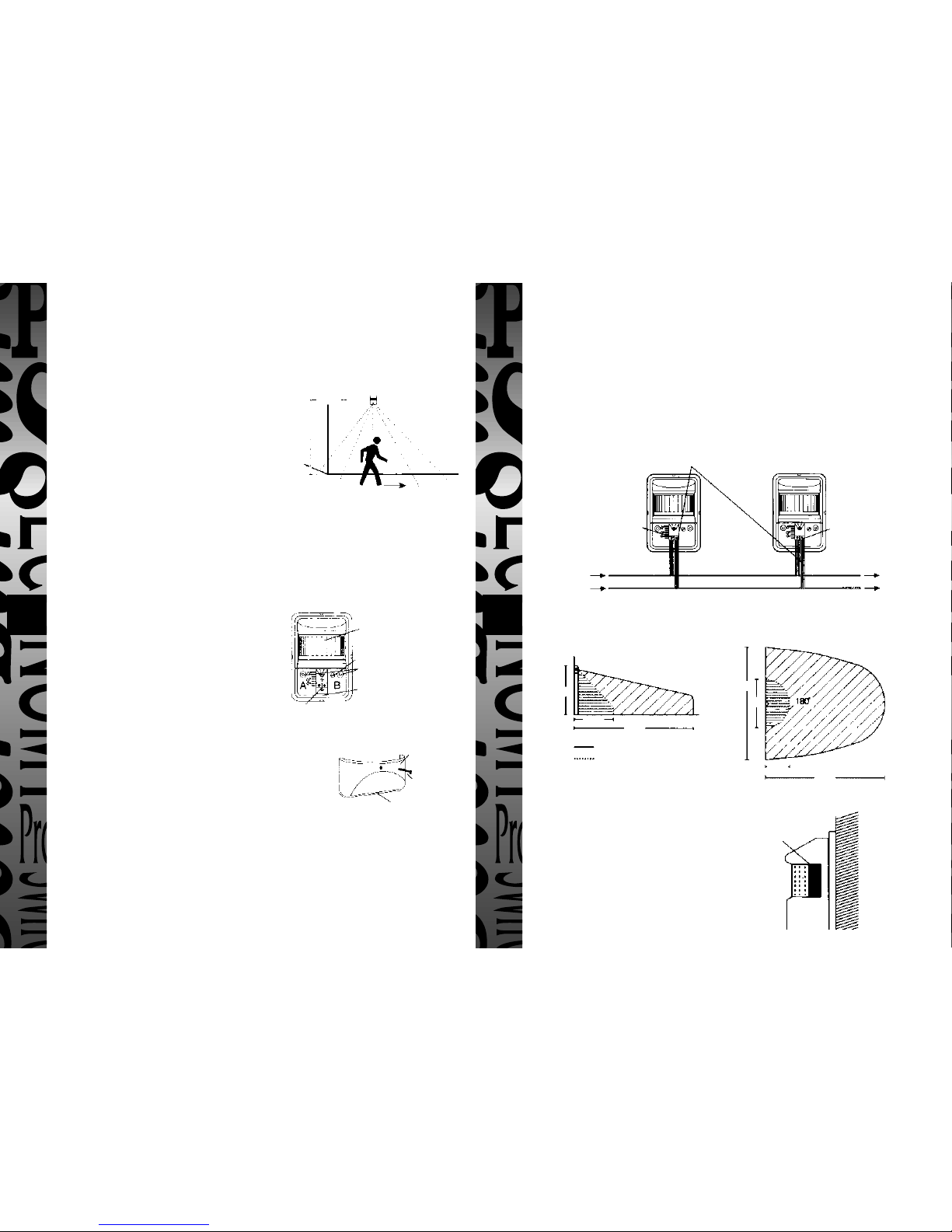
Siting
The Wall Sensor Detector should be mounted
at a height of 2.5 metres. At this height the
sensor can be adjusted within minimum and
maximum settings. Refer to adjusting
detection range.
Maximum sensitivity is achieved when
movement of people is past the detector rather than movement directly
towards or away from it.
False Alarms
It may also respond to cars, anumals, central heating flues, cold moving objects
against a warmer background (e.g. swaying trees in front of a warm wall).
Fixing Sensor Detector
to the Wall
i. Unscrew and pull off front cover
ii. Mark fixing holes A & B and drill holes
iii. Fix unit to the wall using 2 x No 8 1
1
⁄
2
"
(40mm) screws and wallplugs (not
supplied)
iv. Replace front cover on completion
of Wiring and walk testing.
Adjusting Detection Range
i. Unscrew and pull off front cover
ii. Loosen field adjustment screw
iii. Using terminal block slide up or down into position Up=Minimum setting
at 2.5 metres 180° Down=Maximum setting at 15 metres 180° (Refer to
detection range).
iv. Once the range is established lock the terminal block into position by
tightening the field adjustment screw.
v. Replace front cover and secure with cover screw.
Wiring
All Wall Sensor Detectors should be wired in parallel back to the Multi Sensor
Switch terminals zone 1 and 2 (refer to Multi Sensor Switch cable plan).
A low voltage 2 core cable (bell wire) should be used. For convenience wiring
may be looped from one detector to the next. Alternatively a junction box may
be used.
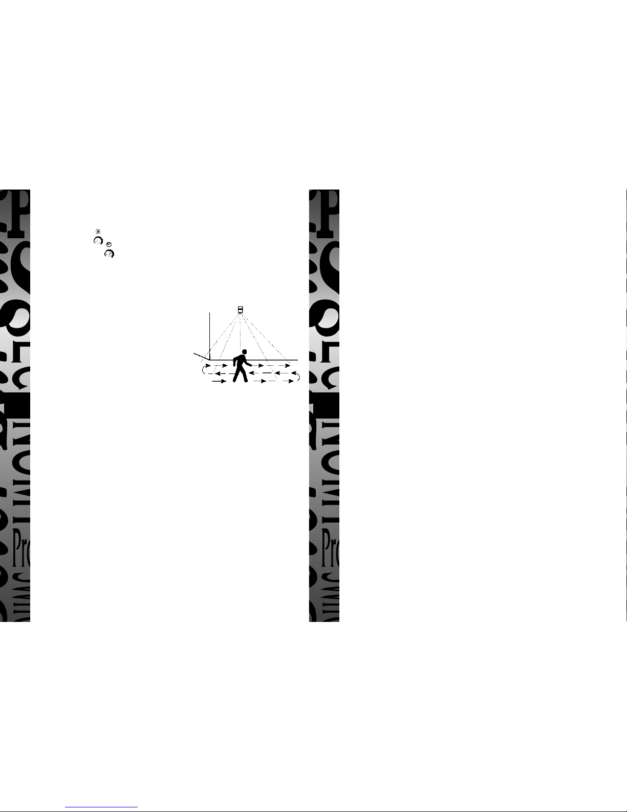
Detection Range
Walk Testing
Before commencing the walk test turn the Light level adjuster on the Multi
Sensor Switch to the day and night setting and both zone 1 and 2 light
on time adjusters to the minimum light on time setting.
Switch on the mains electricity supply to the Multi Sensor Switch and wait 20
seconds for the switch to stablilise.
Starting at a distance greater than 15 meters from the Wall Sensor Detector
walk across the front of the unit gradually
moving closer. Note the position where
detection occurs. The light will remain on for
approximately 3 seconds. Continue this
pattern to establish the full extent of coverage.
Reset the light level and light on time controls
on the controlling switch. Commissioning is
now complete.
2.5m
2.5m
Maximum detection area
Minimum detection area
2.5m
2.5m
15m
20m
3m
15m
180° PIR lens
Fixing holes
Cut out for 2 core
cable entry
Terminal block slides up and down to
adjust detection range
Up = minimum
Down = maximum
Front cover
Front cover
screw
Knock out for 2 core cable entry
Field adjustment screw
Terminal block
The detection angle masking
area may be reduced by
masking the lens with
adhesive PVC tape cut to
required width.
From Multi
Sensor switch
Route 2 core cable through case cut out into terminal blocks and secure
(cable knockout on front cover)
To next Wall
Sensor detector
Terminal block
Low voltage
2 core cable
(Bell wire)
Masking the Detection Area
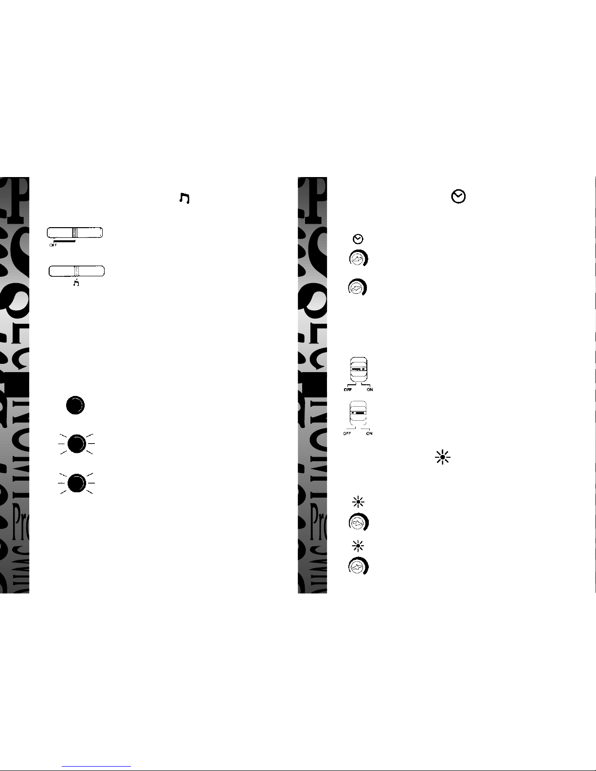
Light ON Time Adjuster
Sets the length of time the light(s) remain on after detection by a Wall Sensor
Detector
Turn adjuster arrow anti-clockwise for minimum on time.
Turn adjuster arrow clockwise for a longer time on period.
Timing is adjustable from approx 5 seconds to 5 minutes.
Zone Link
Both zones can be linked via a removable selector link on the back of the
switch.
ZONE LINK OFF - Light on times operate independently of
each other.
ZONE LINK ON - Light on times are governed by the zone set
with the longest light on time period. All Wall Sensor Detectors
in either zone will operate the system with this link
Light Level Adjuster
The adjustable light level control (100 Lux – 5 Lux determines at what part of
the day the system operates when set in AUTO (PIR) operating mode
Turn adjuster arrow fully clockwise for the day and night
operation.
Turn adjuster arrow anti-clockwise for a darker start operation.
NOTE: There is only one light level adjuster controlling both zones. The wall sensor
detector connected to zone 1 within the darkest lit area sets the light level.
Audible Alarm Selector - OFF/
(Independent to each zone)
Internal buzzer alarm permanently OFF
The internal buzzer alarm will sound for approx.
1 second each time movement is detected by a Wall
Sensor Detector. NOTE: This facility operates over a
24hr period and can function independently of the
operating mode selections (OFF/AUTO/ON) above.
To help distinguish in what zone an intrusion has
occurred. ZONE 1 buzzer sounds a Continuous
bleep – bleeeeeep ZONE 2 buzzer sounds a fast
intermittent bleep – bleepbleepbleepbleep
LED Indicator
(Independent to each zone)
OFF – LED does not show
AUTO – Led shows on detection of movement
detected by the Wall Sensor Detector. The indicator
will remain on for the same period as the light on
time selector. (see light on time adjuster.)
ON – LED remains permanently ON.
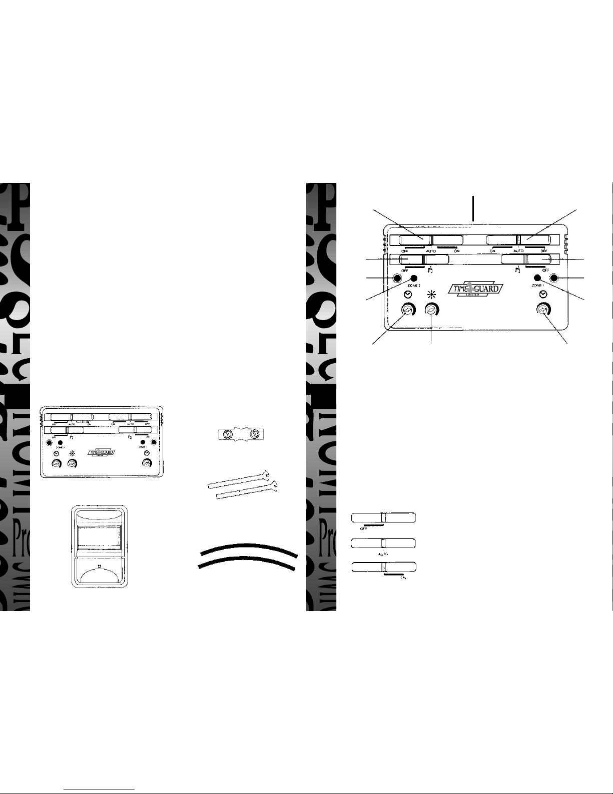
Multi Sensor Switch Controls
Each of the zone controls are independent of each other allowing individual
zone settings or combined operation. NOTE: There is only one light level
adjuster for both zones which is set in conjunction with the sensor detector
connected to zone 1 in the darkest lit area.
Operating Mode Selector OFF/Auto/ON
(Independent to each zone)
Light(s) permanently OFF
Light(s) operational in conjunction with PIR Wall
Sensor Detectors
Light(s) permanently ON
43 6521
Operating mode
selector ZONE 2
CONTROLS ZONE 1
CONTROLS
Audible
alarm
selector
Audible
alarm
selector
40mm
Chrome
screw
40mm
Chrome
screw
LED
indicator
Light on time adjuster
40mm chrome screws
40mm chrome screws
Multi Sensor switch
Multi Sensor switch
Use a Std. 2 gang 25mm deep metal flush
wall box (not supplied)
Use a Std. 2 gang 25mm
deep surface mounted
wall box (not supplied)
Fused Spur
240V Mains Input
To next Zone 2 wall sensor
detector* (max 4 detectors
each zone)
To next Zone 1 wall sensor
detector* (max 4 detectors
each zone)
To Zone 2 Lights
To Zone 1 Lights
1 way terminal block supplied
for earth termination (insulate
and locate inside wall box)
Zone 1 wall
sensor detector
Zone 2 wall
sensor detector
Zone linking selector
Use PVC insulated twin and earth cable 1.5mm2
*Use low voltage 2 core
cable (sleeving supplied
to insulate cable run
inside switch
MULTI SENSOR SWITCH
1 WAY TERMINAL BLOCK
180° WALL SENSOR DETECTOR
Light on time adjusterLight level adjuster
(zones 1 & 2)
LED
indicator
Operating mode
selector
Pack Contents
NOTE: Wall mounting fixing screws and
wallplugs for the Wall Sensor Detector are not
supplied. Use 2 X No 8 11/2" (40mm) screws
(for earth termination – see wiring section)
2 x 40mm CHROME SCREWS
(to secure Multi Sensor Switch to wall box –
see installing switch section)
2 x 165mm LONG PVC INSULATION SLEEVES
(to insulate low voltage 2 core cable inside
switch – see wiring section)
Installing the Multi Sensor Switch
Wall Mounting
The Multi Sensor Switch is for internal siting only and can be either flush
mounted or surface mounted onto an interior wall.
Surface Mounted
Wiring
INSTALLATION SHOULD BE CARRIED OUT BY A COMPETENT DIY
PERSON. IF IN DOUBT CONSULT A QUALIFIED ELECTRICIAN.
THE MAINS SUPPLY TO THE UNIT SHOULD BE FUSED AT:
3 AMPS - Light loads up to 500W
13 AMPS - Light loads between 500-1500W
AND ALSO INCORPORATE AN ON/OFF SWITCH
It must be possible to isolate the supply completely for
installation/maintenance purposes. This can be done by an isolating switch or
at the mains supply switch to the premises.
BEFORE WIRING THE MULTI SENSOR SWITCH ENSURE THAT THE
MAINS IS DISCONNECTED AT SOURCE.
Cable Plan
For mains IN and switched mains OUT (to lights) – use PVC insulated twin and
earth cable 1.5mm
2
. For Wall Sensor Detector connection (zone 1 and zone 2) –
use low voltage 2 core cable (bell wire). IMPORTANT: Use the two strips of
sleeving supplied to insulate the low voltage cable run inside the switch.
Flush Mounted
General
A passive infra-red Multi Sensor Switch and 180° sensor-detector, providing security
lighting control in either 1 or 2 zones. The wall switch is designed to be sited internally
on new or existing installations and operates in conjunction with low-voltage SL099
sensor detectors, mounted externally. Each zone is fully independent and can control
up to 4 sensor-detectors and up to 1500W of lighting. Simple slide-switch controls
allow automatic passive infra-red security or manual ON/OFF operation in both
individual zones. An audible alarm (optional setting) with LED indication sounds on
detection. Light-on-times are adjustable from 5 seconds to 5 minutes in each zone and
a light level control allows dusk till dawn and daylight operation.
INSTALLATION SHOULD BE CARRIED OUT BY A COMPETENT DIY PERSON. IF
IN DOUBT CONSULT A QUALIFIED ELECTRICIAN. PLEASE READ THE
INSTRUCTIONS THOROUGHLY BEFORE COMMENCING WORK.
SAFETY The electricity supply must be disconnected whilst carrying out the installation.
Max 1500W of
lighting each zone
Light ON Time Adjuster
Sets the length of time the light(s) remain on after detection by a Wall Sensor
Detector
Turn adjuster arrow anti-clockwise for minimum on time.
Turn adjuster arrow clockwise for a longer time on period.
Timing is adjustable from approx 5 seconds to 5 minutes.
Zone Link
Both zones can be linked via a removable selector link on the back of the
switch.
ZONE LINK OFF - Light on times operate independently of
each other.
ZONE LINK ON - Light on times are governed by the zone set
with the longest light on time period. All Wall Sensor Detectors
in either zone will operate the system with this link
Light Level Adjuster
The adjustable light level control (100 Lux – 5 Lux determines at what part of
the day the system operates when set in AUTO (PIR) operating mode
Turn adjuster arrow fully clockwise for the day and night
operation.
Turn adjuster arrow anti-clockwise for a darker start operation.
NOTE: There is only one light level adjuster controlling both zones. The wall sensor
detector connected to zone 1 within the darkest lit area sets the light level.
Audible Alarm Selector - OFF/
(Independent to each zone)
Internal buzzer alarm permanently OFF
The internal buzzer alarm will sound for approx.
1 second each time movement is detected by a Wall
Sensor Detector. NOTE: This facility operates over a
24hr period and can function independently of the
operating mode selections (OFF/AUTO/ON) above.
To help distinguish in what zone an intrusion has
occurred. ZONE 1 buzzer sounds a Continuous
bleep – bleeeeeep ZONE 2 buzzer sounds a fast
intermittent bleep – bleepbleepbleepbleep
LED Indicator
(Independent to each zone)
OFF – LED does not show
AUTO – Led shows on detection of movement
detected by the Wall Sensor Detector. The indicator
will remain on for the same period as the light on
time selector. (see light on time adjuster.)
ON – LED remains permanently ON.
Multi Sensor Switch Controls
Each of the zone controls are independent of each other allowing individual
zone settings or combined operation. NOTE: There is only one light level
adjuster for both zones which is set in conjunction with the sensor detector
connected to zone 1 in the darkest lit area.
Operating Mode Selector OFF/Auto/ON
(Independent to each zone)
Light(s) permanently OFF
Light(s) operational in conjunction with PIR Wall
Sensor Detectors
Light(s) permanently ON
43 6521
Operating mode
selector ZONE 2
CONTROLS ZONE 1
CONTROLS
Audible
alarm
selector
Audible
alarm
selector
40mm
Chrome
screw
40mm
Chrome
screw
LED
indicator
Light on time adjuster
40mm chrome screws
40mm chrome screws
Multi Sensor switch
Multi Sensor switch
Use a Std. 2 gang 25mm deep metal flush
wall box (not supplied)
Use a Std. 2 gang 25mm
deep surface mounted
wall box (not supplied)
Fused Spur
240V Mains Input
To next Zone 2 wall sensor
detector* (max 4 detectors
each zone)
To next Zone 1 wall sensor
detector* (max 4 detectors
each zone)
To Zone 2 Lights
To Zone 1 Lights
1 way terminal block supplied
for earth termination (insulate
and locate inside wall box)
Zone 1 wall
sensor detector
Zone 2 wall
sensor detector
Zone linking selector
Use PVC insulated twin and earth cable 1.5mm2
*Use low voltage 2 core
cable (sleeving supplied
to insulate cable run
inside switch
MULTI SENSOR SWITCH
1 WAY TERMINAL BLOCK
180° WALL SENSOR DETECTOR
Light on time adjusterLight level adjuster
(zones 1 & 2)
LED
indicator
Operating mode
selector
Pack Contents
NOTE: Wall mounting fixing screws and
wallplugs for the Wall Sensor Detector are not
supplied. Use 2 X No 8 11/2" (40mm) screws
(for earth termination – see wiring section)
2 x 40mm CHROME SCREWS
(to secure Multi Sensor Switch to wall box –
see installing switch section)
2 x 165mm LONG PVC INSULATION SLEEVES
(to insulate low voltage 2 core cable inside
switch – see wiring section)
Installing the Multi Sensor Switch
Wall Mounting
The Multi Sensor Switch is for internal siting only and can be either flush
mounted or surface mounted onto an interior wall.
Surface Mounted
Wiring
INSTALLATION SHOULD BE CARRIED OUT BY A COMPETENT DIY
PERSON. IF IN DOUBT CONSULT A QUALIFIED ELECTRICIAN.
THE MAINS SUPPLY TO THE UNIT SHOULD BE FUSED AT:
3 AMPS - Light loads up to 500W
13 AMPS - Light loads between 500-1500W
AND ALSO INCORPORATE AN ON/OFF SWITCH
It must be possible to isolate the supply completely for
installation/maintenance purposes. This can be done by an isolating switch or
at the mains supply switch to the premises.
BEFORE WIRING THE MULTI SENSOR SWITCH ENSURE THAT THE
MAINS IS DISCONNECTED AT SOURCE.
Cable Plan
For mains IN and switched mains OUT (to lights) – use PVC insulated twin and
earth cable 1.5mm
2
. For Wall Sensor Detector connection (zone 1 and zone 2) –
use low voltage 2 core cable (bell wire). IMPORTANT: Use the two strips of
sleeving supplied to insulate the low voltage cable run inside the switch.
Flush Mounted
General
A passive infra-red Multi Sensor Switch and 180° sensor-detector, providing security
lighting control in either 1 or 2 zones. The wall switch is designed to be sited internally
on new or existing installations and operates in conjunction with low-voltage SL099
sensor detectors, mounted externally. Each zone is fully independent and can control
up to 4 sensor-detectors and up to 1500W of lighting. Simple slide-switch controls
allow automatic passive infra-red security or manual ON/OFF operation in both
individual zones. An audible alarm (optional setting) with LED indication sounds on
detection. Light-on-times are adjustable from 5 seconds to 5 minutes in each zone and
a light level control allows dusk till dawn and daylight operation.
INSTALLATION SHOULD BE CARRIED OUT BY A COMPETENT DIY PERSON. IF
IN DOUBT CONSULT A QUALIFIED ELECTRICIAN. PLEASE READ THE
INSTRUCTIONS THOROUGHLY BEFORE COMMENCING WORK.
SAFETY The electricity supply must be disconnected whilst carrying out the installation.
Max 1500W of
lighting each zone
PASSIVE INFRA-RED
MULTI SENSOR
SWITCH &
DETECTOR
Cat No. SL055
7 8 109
INSTALLATION & OPERATING
INSTRUCTIONS
HELPLINE
020-8450-0515
For a product brochure please contact:
Timeguard Ltd.
Victory Park, 400 Edgware Road,
London NW2 6ND
Tel: 020-8452-1112
or email csc@timeguard.com
Designed and manufactured in the U.K. 67-057-45 [2]
Specifications
Supply voltage 220 –240V 50Hz
Power consumption 6VA Lamps off
Lighting load Incandescent /tungsten halogen
3000W Maximum (1500W each zone)
SUITABLE FOR FLUORESCENT LIGHTING AND LOW ENERGY BULBS
UP TO 500W MAXIMUM IN EACH ZONE
Light-on-time Adjustable from 5 seconds to 5 minutes.
Timing interval starts from last detection.
Light level Adjustable from 5 lux to 100 lux using zone
1 detector.
Detection coverage 2 independent zones of detection with up to 4 Wall
Sensor Detectors (SL099) each zone. Detector range
up to 15 metres at an ambient temperature of 20°C
and 180° coverage in the horizontal plane.
Protection rating Wall Sensor Detector (SLO99) – IP54
Operating rating -20°C to +50°C
Conforms to directives: 73/23/EEC and 89/336/EEC
5 Year Guarantee
We shall repair or at our option replace this product if it becomes defective
within 5 years of the date of purchase, provided that you return it to us with
proof of purchase. A product becomes defective where it fails due to fault in
the material or workmanship, but not where the failure is caused by an
accident, misuse or neglect. This guarantee does not effect your rights under
statute or common law.
Points to Remember
• Installation should be carried out by a competent DIY person. If in doubt
consult a qualified electrician.
• The electricity supply must be disconnected whist carrying out the
installation.
• An earth connection must be made for safety.
• The Multi Sensor Switch is for internal siting only. Wall Sensor Detectors
are mounted externally.
• Use the 2 strips of insulating sleeve (supplied) to insulate the 2 core low
voltage cable run inside the Multi Sensor Switch.
• Wall Sensor Detectors should be mounted at a height of 2.5 metres. At this
height the detector can be adjusted within minimum and maximum
settings. Refer to adjust detection range setting.
• Set light level/time on controls as shown under section heading.
• In normal use a built-in light sensor prevents daylight operation unless
light adjuster is set to day and night operation.
• False alarms may occur (see siting).
• The Sensor detector is more sensitive to movement across the detector
rather than directly towards or away from it.
• To help distinguish in what zone an intrusion has occurred:
ZONE 1 buzzer sounds a continuous bleep – bleeeeeep ZONE 2 buzzer
sounds a fast Intermittent bleep –bleepbleepbleepbleep
Installing the Wall Sensor Detector
A maximum of 8 detectors – 4 each zone can be installed using low voltage 2
core cable (bell wire).
Siting
The Wall Sensor Detector should be mounted
at a height of 2.5 metres. At this height the
sensor can be adjusted within minimum and
maximum settings. Refer to adjusting
detection range.
Maximum sensitivity is achieved when
movement of people is past the detector rather than movement directly
towards or away from it.
False Alarms
It may also respond to cars, anumals, central heating flues, cold moving objects
against a warmer background (e.g. swaying trees in front of a warm wall).
Fixing Sensor Detector
to the Wall
i. Unscrew and pull off front cover
ii. Mark fixing holes A & B and drill holes
iii. Fix unit to the wall using 2 x No 8 1
1
⁄
2
"
(40mm) screws and wallplugs (not
supplied)
iv. Replace front cover on completion
of Wiring and walk testing.
Adjusting Detection Range
i. Unscrew and pull off front cover
ii. Loosen field adjustment screw
iii. Using terminal block slide up or down into position Up=Minimum setting
at 2.5 metres 180° Down=Maximum setting at 15 metres 180° (Refer to
detection range).
iv. Once the range is established lock the terminal block into position by
tightening the field adjustment screw.
v. Replace front cover and secure with cover screw.
Wiring
All Wall Sensor Detectors should be wired in parallel back to the Multi Sensor
Switch terminals zone 1 and 2 (refer to Multi Sensor Switch cable plan).
A low voltage 2 core cable (bell wire) should be used. For convenience wiring
may be looped from one detector to the next. Alternatively a junction box may
be used.
Detection Range
Walk Testing
Before commencing the walk test turn the Light level adjuster on the Multi
Sensor Switch to the day and night setting and both zone 1 and 2 light
on time adjusters to the minimum light on time setting.
Switch on the mains electricity supply to the Multi Sensor Switch and wait 20
seconds for the switch to stablilise.
Starting at a distance greater than 15 meters from the Wall Sensor Detector
walk across the front of the unit gradually
moving closer. Note the position where
detection occurs. The light will remain on for
approximately 3 seconds. Continue this
pattern to establish the full extent of coverage.
Reset the light level and light on time controls
on the controlling switch. Commissioning is
now complete.
2.5m
2.5m
Maximum detection area
Minimum detection area
2.5m
2.5m
15m
20m
3m
15m
180° PIR lens
Fixing holes
Cut out for 2 core
cable entry
Terminal block slides up and down to
adjust detection range
Up = minimum
Down = maximum
Front cover
Front cover
screw
Knock out for 2 core cable entry
Field adjustment screw
Terminal block
The detection angle masking
area may be reduced by
masking the lens with
adhesive PVC tape cut to
required width.
From Multi
Sensor switch
Route 2 core cable through case cut out into terminal blocks and secure
(cable knockout on front cover)
To next Wall
Sensor detector
Terminal block
Low voltage
2 core cable
(Bell wire)
Masking the Detection Area
Table of contents
Other Timeguard Accessories manuals


