TimeIPS PROX-WEIG-HID User manual

PROX-WEIG-HID
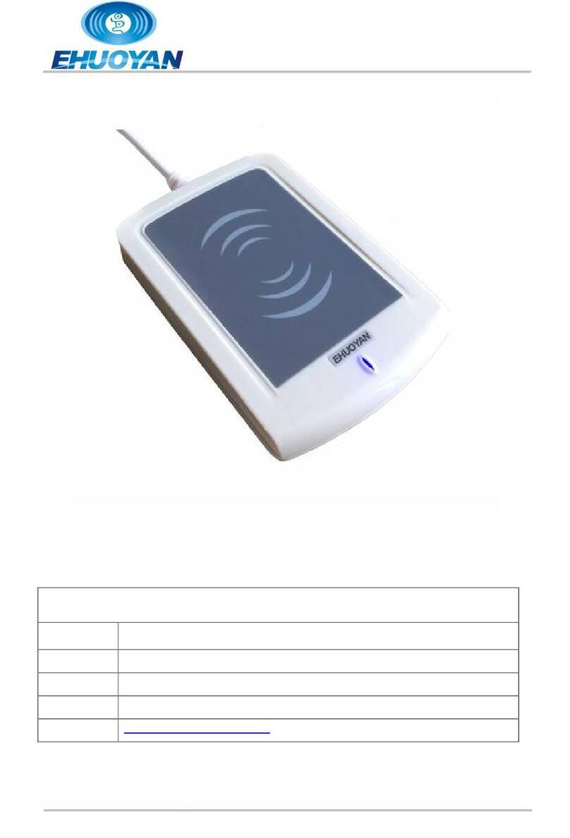
Hardened HID Proximity Badge Reader
Installation Guide

Table of Contents
Overview.....................................................................................................................2
Additional Re uired E uipment..................................................................................2
Installation Overview..................................................................................................3
Mount and Connect the Proximity Reader..................................................................4
Connect Power and USB Cable..................................................................................5
Configure Badge Numbers..........................................................................................6
Train Employees .........................................................................................................7
Technical Support........................................................................................................8
System Specifications.................................................................................................8
Overview
The TimeIPS Hardened HID Proximity Reader features:
•Environmentally sealed, wide temperature range reader, suitable for
outdoor installation
•Reads 125KHz HID-type 26 bit proximity identification badges
•Included USB adapter box should be mounted indoors, near the TimeIPS
system or network clock
•Compatible with all TimeIPS systems. Plugs into a USB connector on the
back of the TimeIPS LCD display or TimeIPS system.
Additional Required Equipment
●Connecting wire from Proximity Reader to USB converter box
●TimeIPS system or Network Clock
●Proximity badges or tags
○Available from TimeIPS
○Provide your own compatible badges
Page 2 http://support.timeips.com 316.264.1600 TimeIPS

Installation Overview
The TimeIPS proximity system consists of the following components:
1. Hardened Prox Reader
2. Connecting Cable (Customer supplied)
3. USB Converter box
4. Power Adapter
5. USB Cable
6. TimeIPS system or Network Clock (Customer supplied)
In a typical installation, the Hardened Proximity Reader will be installed in
an exposed area, such as outdoors or in an industrial setting. Wiring will be
run from the mounting point to a protected indoor location where the USB
converter box can be installed within a few feet of a TimeIPS
system/Network Clock, and an AC power outlet for the Power Adapter.
TimeIPS http://support.timeips.com 316.264.1600 Page 3
Power Adapter
USB Converter
TimeIPS System or
Network Clock
USB Cable
Connecting
Cable

Mount and Connect the Proximity Reader
After selecting the installation location for the proximity reader and the USB
converter box, run a wire between the two locations. Recommended wire is
shielded AWG 22 four conductor low voltage wire, up to 100 feet. Longer
lengths, up to 500 feet may be possible with thicker (AWG 18) wire.
Open the back of the proximity reader using a hex wrench to release the
mounting plate from the back of the hardened prox reader. Attach this to a
wall or other smooth surface and bring wiring through the center hole.
Use crimp connectors, wire nuts, or a terminal block to connect the Red,
Green, White and Black/Purple wires on the prox reader to your own wires.
Tuck the wires back in the wall and mount the prox reader to the plate.
Page 4 http://support.timeips.com 316.264.1600 TimeIPS
Weigand to USB Converter
Red VH
Green W0
White W1
Black GND
Purple GND
range No Connection
Grey No Connection
Brown No Connection
Environmentally Sealed
Proximity Reader
Wiegand to
USB Converter

At the USB converter box, use a small flat screw driver to loosen the
terminal blocks next to “VH” “W0” “W1” and “Gnd” and insert the wires as
shown in the diagram below. (The white wire is shown as dashes.) Tighten
the screws to ensure a good connection.
Connect Power and U B Cable
Connect the power adapter to the DC Power Jack on the USB Converter and
plug into an AC outlet.
When power is connected, the proximity reader should beep to indicate it
has received power. If the proximity reader does not beep when the power
is connected, please check the wiring.
Connect the USB cable to the USB port on the USB converter. Connect the
other end to a free USB port on the back of an LCD display or directly to a
USB port on the back of a TimeIPS system.
Note that it takes 10-15 seconds before the reader will respond if plugged
into a running TimeIPS system. There is no need to shutdown the system to
attach or detach the reader.
Presenting a HID badge within about 1 inch of the surface of reader should
result in a beep. If everything is connected correctly, TimeIPS will receive
the badge number. Follow the instructions for configuring badge numbers
in TimeIPS on the following pages.
TimeIPS http://support.timeips.com 316.264.1600 Page 5
Parallel
Port
Connector

Configure Badge Numbers
Each proximity badge (card or tag) has a uni ue internal number. Some
styles of badges may have a number printed on them that matches the
internal number. However, many are blank or have a number that is NOT
the same as the internal number.
There are two ways to connect a badge to an employee. Open TimeIPS and
click on Administration. Then:
1) Open Employee Management → Employees. Select the employee
on the list by clicking the “+” next to their name and then enter the
badge number in the ID / Badge field. Do NOT enter any leading
zero(s).
2) Open Clocking → ID/Badge Functions, add a function where the
Original is the internal number of the card or tag and the
Replacement is the employee's ID/Badge number.
If your badges have the internal number printed, option 1 is generally the
easiest.
If your badges do not have a number printed on them, or if the number does
not match the internal number, there are two options:
1) Determine the number of the badge as follows: Connect the USB
cable from the converter box to a personal computer. Open a word
processor or spreadsheet and present the badge to the reader. The
internal number of the badge will appear as if you typed it. If you
see an asterisk (*) at the beginning of the resulting number, it is
NOT part of the badge number.
Page 6 http://support.timeips.com 316.264.1600 TimeIPS
A Badge Number may be printed on some badges.
This may or may not match the internal number.

To speed the process of entering multiple badges, plug the USB
cable into your computer, click in the “ID/Badge” field for your
employee within TimeIPS and present the badge.
2) Give employees convenient badge numbers, such as 1000, 1001,
etc., then connect the badge to the employee at the clock. To do
this, a manager will need a list of employee ID/Badge numbers and
the proximity badges to connect. At the clock:
a) Press enter to access the system menu
b) Enter a manager badge number and pin when prompted
c) Select User Admin, then Enroll Badges.
d) Enter the Employee's ID/Badge number, then present the badge
to connect them.
e) After enrolling badges, either select Update Settings from the
System Admin menu, or wait about 5 minutes for the clock to
update its settings automatically.
Train Employees
Using the badges
•Bring the badge within an inch of the reader to clock in or out
•If used with a keypad, enter clock notes, job numbers or status
codes before presenting card.
•Present the card in any orientation that is flush to the reader
If the clock is successful, an audible alert will be heard for “In” or “Out”
and the LCD display will indicate the current date and time, employee name
and the time in or out.
Troubleshooting
•If badges do not read, try unplugging and reconnecting the USB
connection and/or the power to the USB converter.
TimeIPS http://support.timeips.com 316.264.1600 Page 7

Technical upport
Technical Support Resources:
1. Our support web site at http://support.timeips.com offers extensive
resources including documentation and our knowledge-base. Please check
our support web site first, as it provides complete answers and instructions
on almost everything. In the "Knowledge Base Search:" box, enter a few
words describing your uestion. For example, if you have a uestion on
the badge functions, type "badge functions" and browse the articles listed.
2. If you have a uestion not answered on our support site, you can call or
email us. A serial number or registration number is re uired for this
service. Additional support can be purchased by calling TimeIPS, or by
visiting our web site at http://secure.timeips.com.
3. If you have a simple uestion, or need direction on how to use our support
resources, feel free to email us at [email protected]. If your uestion
is uick, we'll be happy to help. If it's not, we'll let you know that you
need to purchase additional support.
upport website http://support.timeips.com
upport phone number 316.264.1600
ystem pecifications
This manual is copyright 2004-2012 TimeIPS, Inc. TimeIPS and the TimeIPS logos are registered
trademarks of TimeIPS, Inc. All other trademarks are the property of their respective owners.
Thank you for reading this manual carefully. If you noticed errors, have any suggestions or found
typographical problems, we want to know! Please send an email with the version code below and your
feedback to [email protected] We appreciate your time.
Version: PROX-WEIG-HID_1.0.0 120118
Page 8 http://support.timeips.com 316.264.1600 TimeIPS
System Specs:
Approximate dimensions:
4.5in (11 mm ) x 2.7 in (70mm) x .78in
(20mm)
Approximate weight:
~0.75lb (~340g
Power:
7.5 to 15 VDC, 150mA (Max
Operating environment: (Reader Only
-22° - 150°F (-30° - 65°C
Operating environment: (USB Converter Box
32° - 90°F (0° - 33°C non-condensing
System Requirements:
TimeIPS IPS100, IPS200 or IPS300 class
system
Table of contents
Other TimeIPS Card Reader manuals
