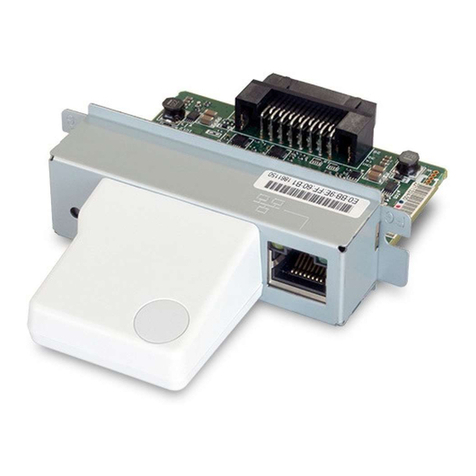
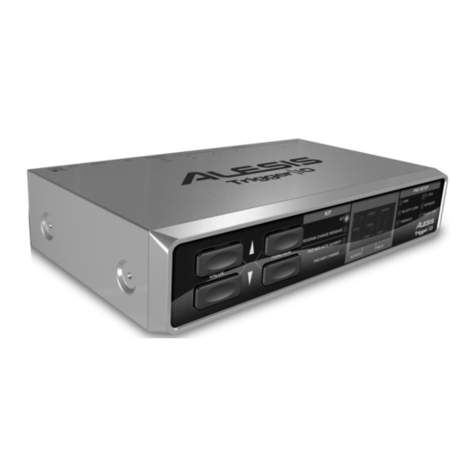
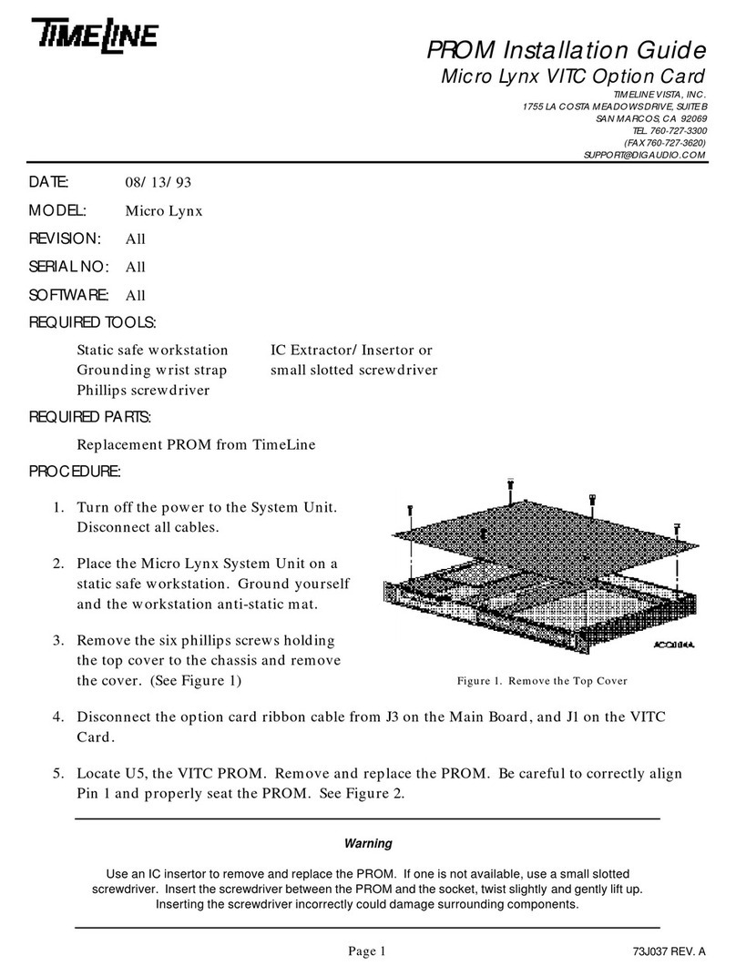
TimeLine Micro Lynx VITC Option Card User manual
Other TimeLine Recording Equipment manuals
TimeLine
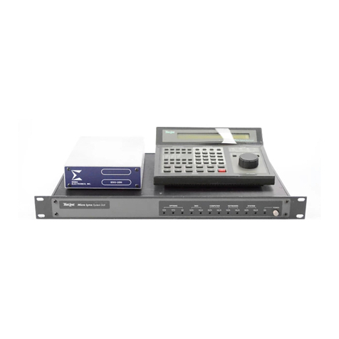
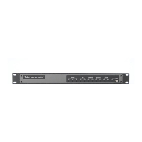
TimeLine Micro Lynx System Unit User manual
TimeLine
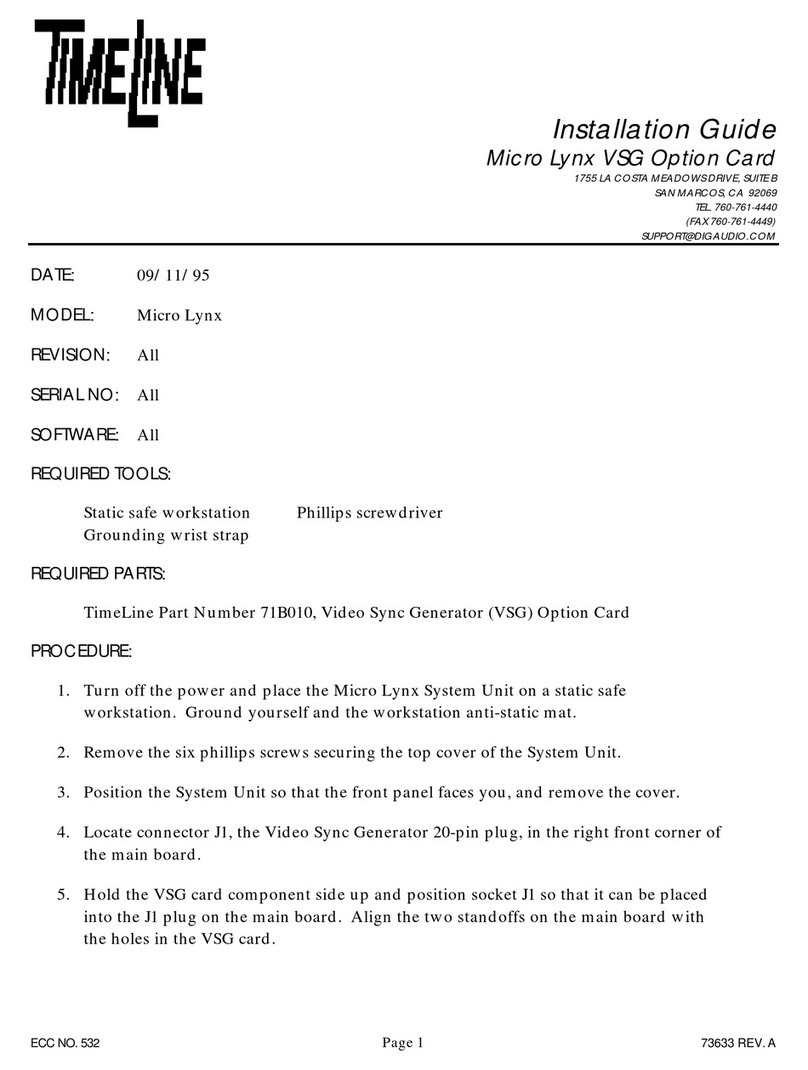
TimeLine Micro Lynx ACG Option Card User manual
TimeLine
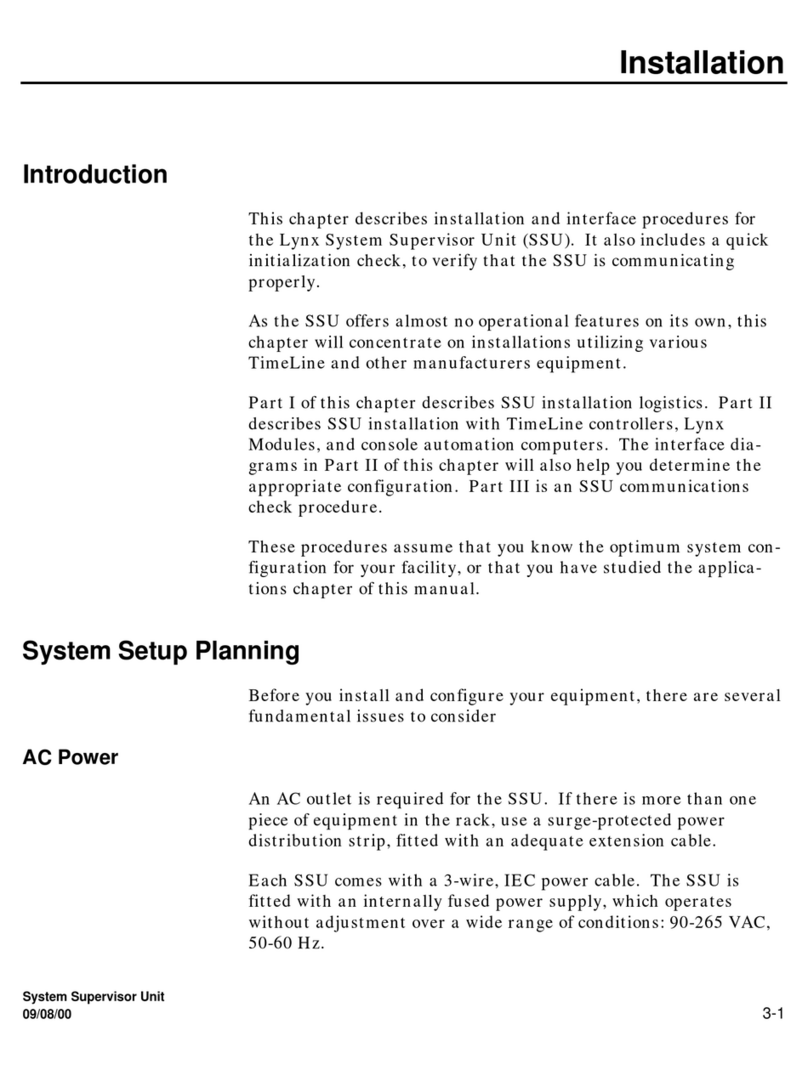
TimeLine Micro Lynx VSG Option Card User manual
TimeLine
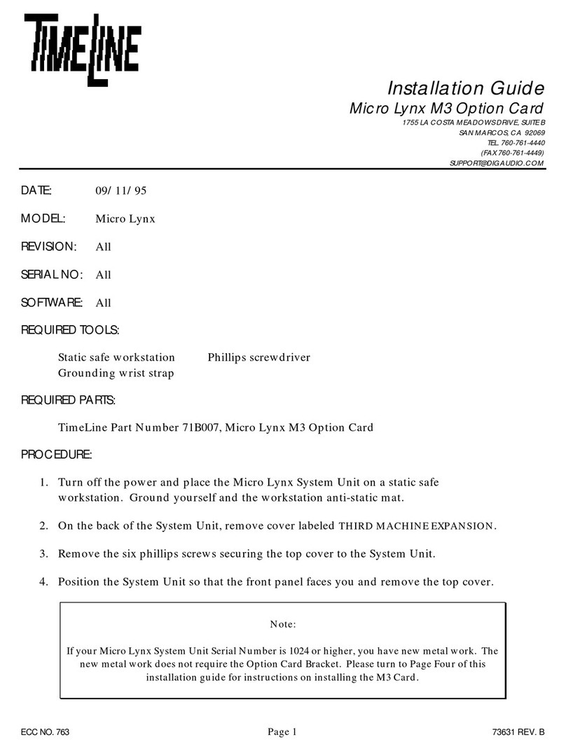
TimeLine Lynx Keyboard Control Unit User manual
TimeLine
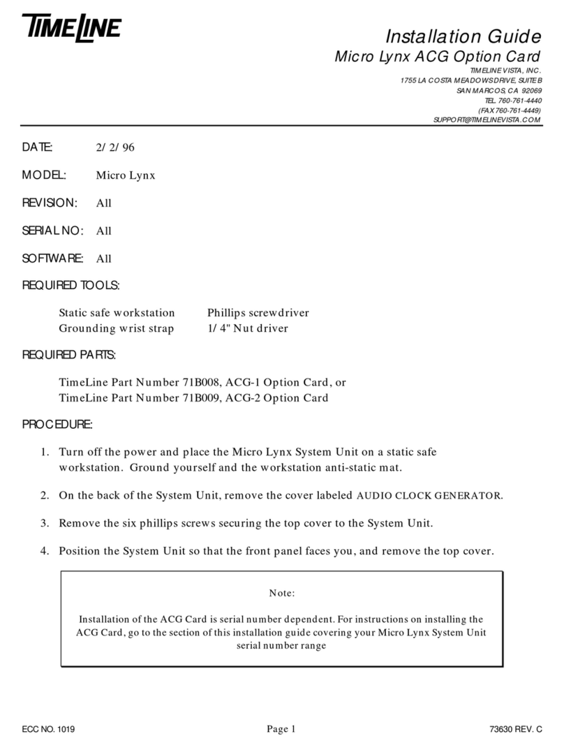
TimeLine Micro Lynx M3 Option Card User manual
TimeLine
TimeLine Micro Lynx ACG-1 Option Card User manual
TimeLine
TimeLine Micro Lynx VITC Option Card User manual

TimeLine
TimeLine Micro Lynx M3 Option Card User manual
Popular Recording Equipment manuals by other brands
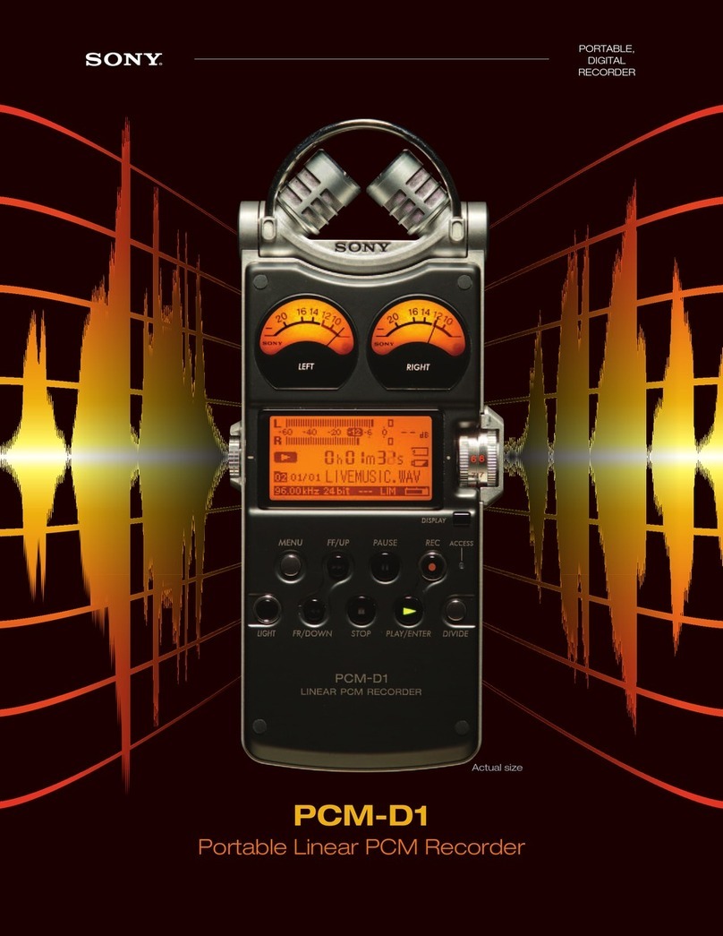
Sony
Sony PCMD1 - Professional XLR Microphone Preamp Brochure & specs
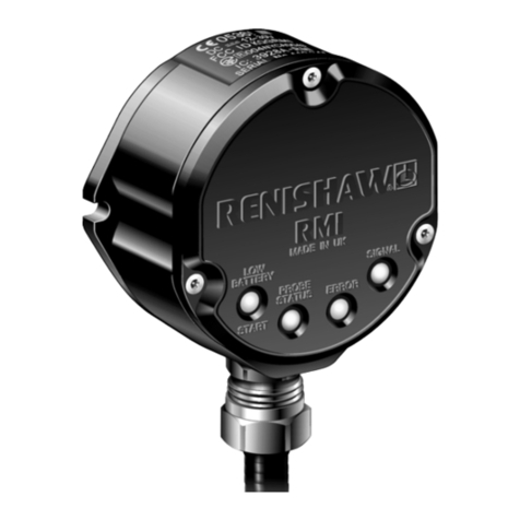
Renishaw
Renishaw RMI Installation and user guide
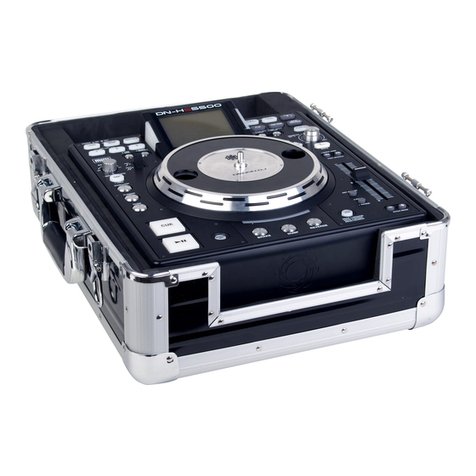
Denon
Denon Hs 5500 - Dn - Direct Drive Turntable Media... Midi specifications

Osram
Osram e:cue Bridge8 INFORMATION FOR USE

Tews Technologies
Tews Technologies TPMC872 user manual
Goodmans
Goodmans GD11FVZS1 quick start guide


