TimeLine Micro Lynx ACG-1 Option Card User manual

ECC NO. 1019 Page 173630 REV. C
Installation Guide
Micro Lynx ACG Option Card
TIMELINE VISTA, INC.
1755 LA COSTA MEADOWS DRIVE, SUITE B
SAN MARCOS, CA 92069
TEL. 760-761-4440
(FAX 760-761-4449)
DATE: 2/2/96
MODEL: Micro Lynx
REVISION: All
SERIAL NO: All
SOFTWARE: All
REQUIRED TOOLS:
Static safe workstation Phillips screwdriver
Grounding wrist strap 1/4" Nut driver
REQUIRED PARTS:
TimeLine Part Number 71B008, ACG-1 Option Card, or
TimeLine Part Number 71B009, ACG-2 Option Card
PROCEDURE:
1. Turn off the power and place the Micro Lynx System Unit on a static safe
workstation. Ground yourself and the workstation anti-static mat.
2. On the back of the System Unit, remove the cover labeled AUDIO CLOCK GENERATOR.
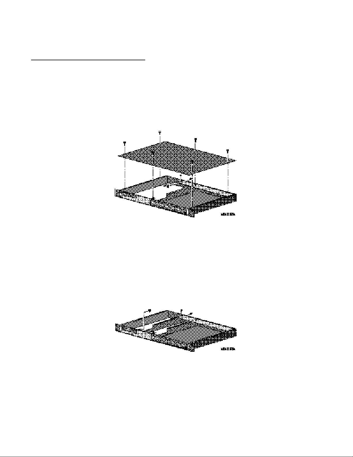
3. Remove the six phillips screws securing the top cover to the System Unit.
4. Position the System Unit so that the front panel faces you, and remove the top cover.
Note:
Installation of the ACG Card is serial number dependent. For instructions on installing the
ACG Card, go to the section of this installation guide covering your Micro Lynx System Unit
serial number range
Micro Lynx ACG Option Card
ECC NO. 1019 Page 273630 REV. C
PROCEDURE (continued):
System Unit Serial Numbers 104-1068
Install the Option Card Bracket
5. The Back Panel PCB is located at the top back of the chassis, horizontal to the back
panel. Remove the "L" shaped bracket supporting the Back Panel PCB by removing
the phillips screws; one on the left side of the board and the other on the back panel,
to the right of the SYSTEM TALLY connector. The bracket is no longer needed, keep
the phillips screws.
Figure 1. Remove Support Bracket
6. Hold the Option Card bracket so that the large cutout is face up. Set the front of the
bracket in place on the threaded stud on the inside of the front panel. Set the bracket
down and slide it under the left edge of the Back Panel PCB.
7. Insert and tighten the screws removed from the back panel, and from the Back Panel
PCB. Place a nut on the threaded stud and secure the bracket to the front panel.
(See Figure 2.)
Figure 2. Install the Option Card Bracket

Micro Lynx ACG Option Card
ECC NO. 1019 Page 373630 REV. C
PROCEDURE (continued):
Install the ACG Option Card
8. Locate and remove the black rubber bumper on the corner of the ACG Card. (See Figure
3.)
9. The ACG Card is mounted on the left side of the System Unit.
10. If you have the M3 or VITC Card already installed in the Micro Lynx, remove the
Option Card cable before installing the ACG Card.
11. The Option Card cable is a ribbon cable with four connectors attached. On one end of
the cable, the second connector is about 3.5" from the end. Insert this end into
connector J1 on the component side of the ACG Card. The connector should be
attached so that the cable falls away from the ACG Card as illustrated in Figure 3.
Figure 3. Option Cable Installation
12. Position the ACG Card component side down with connector J1 toward the front of
the System Unit. Approximately 1.25" from the J1 connector, bend the Option Card
cable under, so that it makes a right-angle turn (the unused connectors on the cable
will face the chassis bottom), as shown in Figure 3.
13. Hold the folded Option Card cable over the cutout in the Option Card bracket, tilt and
slide the left side of the card into the groove, along the top of the Micro Lynx Side
Panel.
14. As the card slides into the groove, lie it flat on the Option Card bracket.
15. Slide the ACG Card against the back panel, so that the AES/EBU connector and the
O.S. OUT, WORD OUT and CLOCK IN jacks are seated in the appropriate cutouts in the
back panel. Insert the washers and nuts onto the BNC connectors.
Micro Lynx ACG Option Card
ECC NO. 1019 Page 473630 REV. C
PROCEDURE (continued):
16. Insert two phillips screws through the ACG Card into the Option Card bracket
standoffs and tighten.
17. If the M3 Card is fitted, insert the Option Card cable connector into J1 on the M3
Card. If the VITC Card is fitted, insert the Option Card cable connector into J1 on the
VITC Card.
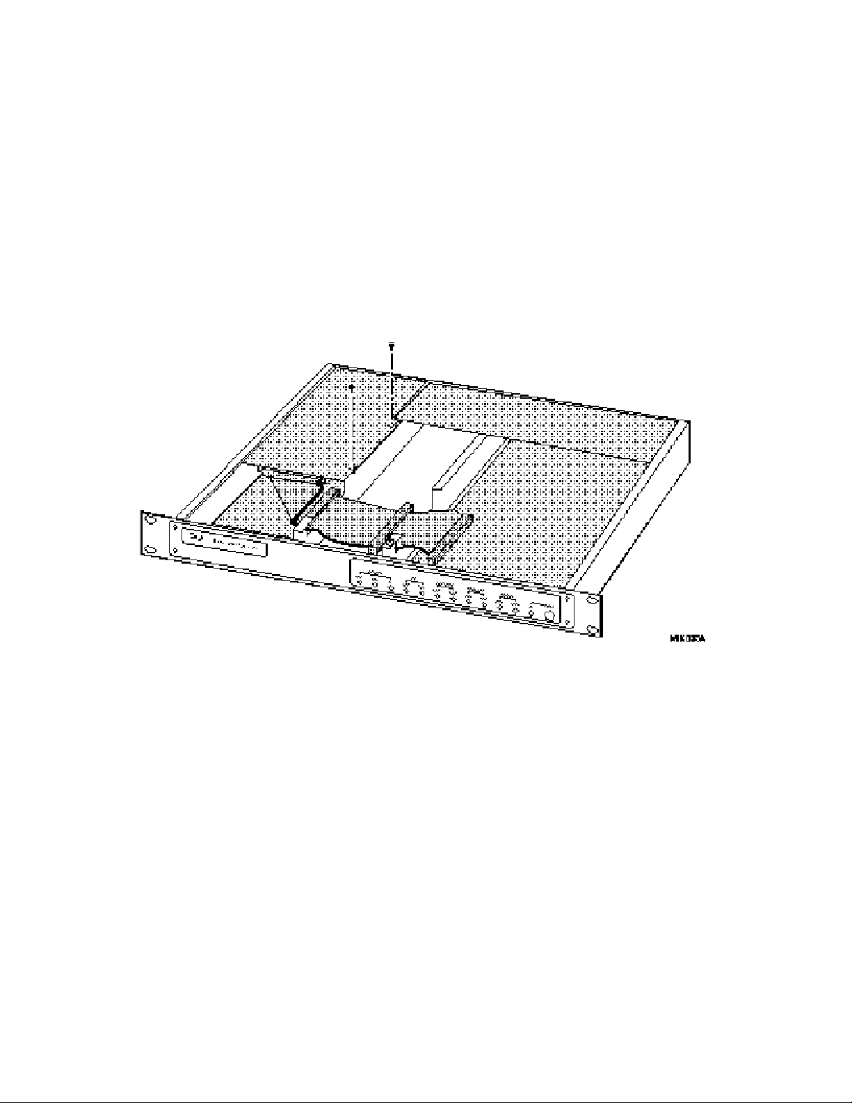
18. Connect the other end of the cable into J3 on the Main Board. The unused connectors
will lie in the open area in the middle of the System Unit, unless you have option cards
installed.
Figure 4. Installation of ACG Card
19. Replace the top cover and the six phillips screws.
20. Power up the System Unit. The Micro Lynx will recognize the ACG Card on power
up and the ACG LED on the System Unit OPTION Section will turn on. Press SETUP,
ACG, to configure the card functions.

Micro Lynx ACG Option Card
ECC NO. 1019 Page 573630 REV. C
PROCEDURE (continued):
System Unit Serial Numbers 1068-1953
Install the ACG Option Card Bracket
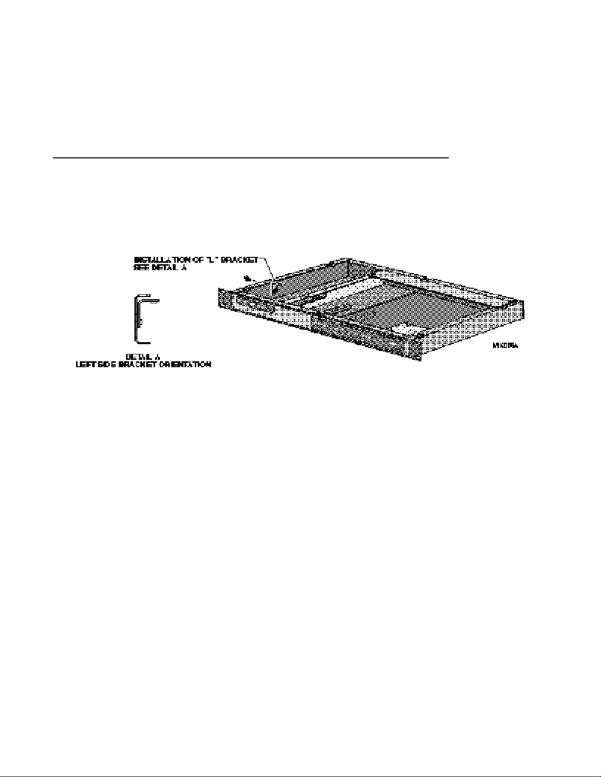
5. Remove the “L” shaped bracket supporting the Back Panel PCB. Relocate this bracket
to the left side of the chassis as shown in Detail A and secure using the phillips screw
supplied in the ACG Option Installation Kit. (See Figure 5.)
Figure 5. Relocation of "L" Bracket
6. Remove the M3 Card, if installed. Remove the nut on the left threaded stud securing
the front panel to the chassis.
7. Hold the ACG Option Card bracket diagonally across the chassis with the cable
opening to the front. Set the front of the bracket in place on the threaded stud, inside
the chassis. Slide the bracket under the left edge of the Back Panel PCB and the VITC
Card (if installed).
8. Insert and tighten the screw removed from the back panel, and from the Back Panel
PCB. Replace the nut on the front panel threaded stud to secure the bracket. (See Figure
6.)
Figure 6. Install the ACG Option Card Bracket

Micro Lynx ACG Option Card
ECC NO. 1019 Page 673630 REV. C
Install the ACG Option Card
9. Reinstall the M3 Card, if it was removed. The ACG Card is mounted on the left side
of the System Unit, above the M3 Card.
10. Remove the mounting standoffs from the 9-pin connector on the ACG Card.

Micro Lynx ACG Option Card
ECC NO. 1019 Page 773630 REV. C
PROCEDURE (continued):
11. The Option Card cable is a ribbon cable with four connectors attached. On one end of
the cable, the second connector is about 3.5" from the end. Insert this end into
connector J1 on the component side of the ACG Card. The connector should be
attached so that the cable falls away from the ACG Card, as illustrated in Figure 3.
12. Position the ACG Card component side down with connector J1 toward the front of the
System Unit. Approximately 1.25" from the J1 connector, bend the Option Card cable
under, so that it makes a right-angle turn (the unused connectors on the cable will face the
chassis bottom).
13. Insert the folded Option Card cable through the opening in the Option Card bracket.
14. Lie the ACG Card flat on the Option Card bracket. Slide the ACG Card against the
back panel, so that the AES/EBU connector and the O.S. OUT, WORD OUT and CLOCK IN
jacks are seated in the appropriate cutouts in the back panel. Insert the washers and
nuts onto the BNC connectors. Replace the mounting standoffs on the 9-pin connector.
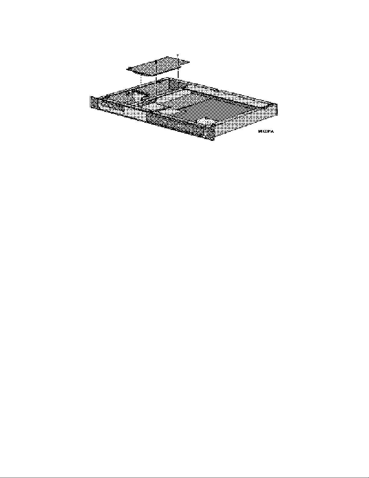
15. The corner of the ACG Card, with the black rubber bumper, will rest on the "L"
bracket installed on the side of the chassis in Step 5. Insert two phillips screws
through the ACG Card into the Option Card bracket and tighten. (See Figure 7.)
Figure 7. Install the ACG Card
16. If the M3 Card is fitted, insert the Option Card cable connector into J1 on the M3
Card. If the VITC Card is fitted, insert the Option Card cable connector into J1 on the
VITC Card.
17. Connect the other end of the cable into J3 on the Main Board. The unused connectors
will lie in the open area in the middle of the System Unit, unless you have option cards
installed.
18. Replace the top cover and the six phillips screws.
Micro Lynx ACG Option Card
ECC NO. 1019 Page 873630 REV. C
19. Power up the System Unit. The Micro Lynx will recognize the ACG Card on power
up and the ACG LED on the System Unit OPTION Section will turn on. Press SETUP,
ACG, to configure the card functions.
PROCEDURE (continued):
System Unit Serial Numbers 1954 and higher (ACG option bracket pre-fitted)
Install the ACG Option Card “L” Bracket
5. Locate the “L” shaped bracket in the ACG Option Card Kit. Install this bracket to the
left side of the chassis as shown in Detail A and secure using the phillips screw
supplied in the kit. (See Figure 8.)
Figure 8. Location of "L" Bracket
6. Remove the mounting standoff from the 9-pin connector on the ACG Card.
7. The Option Card cable is a ribbon cable with four connectors attached. On one end of
the cable, the second connector is about 3.5" from the end. Insert this end into
connector J1 on the component side of the ACG Card. The connector should be
attached so that the cable falls away from the ACG Card, as illustrated in Figure 3.
8. Position the ACG Card component side down with connector J1 toward the front of the
System Unit. Approximately 1.25" from the J1 connector, bend the Option Card cable
under, so that it makes a right-angle turn (the unused connectors on the cable will face the
chassis bottom).
9. Insert the folded Option Card cable through the opening in the Option Card bracket.
10. Lie the ACG Card flat on the Option Card bracket. Slide the ACG Card against the
back panel, so that the AES/EBU connector and the O.S. OUT, WORD OUT and CLOCK IN
jacks are seated in the appropriate cutouts in the back panel. Insert the washers and
nuts onto the BNC connectors. Replace the mounting standoffs on the 9-pin connector.
11. The corner of the ACG Card, with the black rubber bumper, will rest on the “L”
bracket installed on the side of the chassis in Step 5. Insert two phillips screws
through the ACG Card into the Option Card bracket and tighten. (See Figure 9.)
Micro Lynx ACG Option Card
ECC NO. 1019 Page 973630 REV. C
PROCEDURE (continued):
Figure 9. Install the ACG Card
12. If the M3 Card is fitted, insert the Option Card cable connector into J1 on the M3
Card. If the VITC Card is fitted, insert the Option Card cable connector into J1 on the
VITC Card.
13. Connect the other end of the cable into J3 on the Main Board. The unused connectors
will lie in the open area in the middle of the System Unit, unless you have option cards
installed.
14. Replace the top cover and the six phillips screws.
15. Power up the System Unit. The Micro Lynx will recognize the ACG Card on power
up and the ACG LED on the System Unit OPTION Section will turn on. Press SETUP,
ACG, to configure the card functions.
This manual suits for next models
3
Other TimeLine Recording Equipment manuals

TimeLine
TimeLine Micro Lynx VITC Option Card User manual

TimeLine
TimeLine Micro Lynx ACG Option Card User manual

TimeLine
TimeLine Micro Lynx System Unit User manual

TimeLine
TimeLine Micro Lynx VSG Option Card User manual

TimeLine
TimeLine Micro Lynx VITC Option Card User manual

TimeLine
TimeLine Lynx Keyboard Control Unit User manual

TimeLine
TimeLine Micro Lynx M3 Option Card User manual

TimeLine
TimeLine Micro Lynx M3 Option Card User manual


