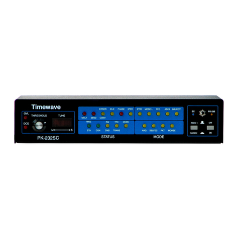
Timewave PK-96 User manual

From The N3UJJ.COM Document LibraryFrom The N3UJJ.COM Document Library
PK-96
Operating
Manual
TimewaveTechnology Inc.
58
E.
Plato Blvd.
St. Paul,
MN
55107
http://www.timewave.com
July 1997

From The N3UJJ.COM Document LibraryFrom The N3UJJ.COM Document Library
iiI
PK-96
Packet
Controller
Operating
Manual
Welcome
Thank you for purchasing an Timewave/AEA product! Before you go any further, please fill out and
return the enclosed Warranty Registration Card. From time to time, Timewave offers updates
to
its
products-we
can only tell you about these updates
if
we have your warranty card on file, so send it
in
if
you haven't already done so.
FCC Regulations
This device complies with Part
15
of
the FCC rules. These rules are designed to provide reasonable
protection against harmful interference in a residential installation. This device generates, uses, and
can radiate radio frequency energy and,
if
not installed and used in accordance with the instructions,
may cause harmful interference to radio communications. However, there is no guarantee that interfer-
ence will not occur in a particular installation.
If
this device does cause harmful interference to radio
or television reception, which can be determined by turning the device off and on, the user is encour-
aged to try to correct the interference by one or more
of
the following measures:
• Reorient or relocate the receiving antenna.
Increase the separation between the device and receiver.
• Connect the device into
an
outlet on a circuit different from that to which the receiver is connected.
Consult the dealer or an experienced radio/TV technician for help.
Changes or modifications not expressly approved by the manufacturer will void the user's authority to
operate the device.
You
must use shielded cables for all device connections, then tie all grounding wires/shields
to
a
single point, normally the radio.
You
need an effective station ground or you'll have problems when
RFI infiltrates your equipment and causes all kinds
of
unexpected problems.
Disclaimer
As part
of
its continuing program
of
product improvement, Timewave reserves the right to make
changes in this product's specifications or documentation. Timewave also reserves the right to incor-
porate and issue any information thus supplied in whatever manner it deems suitable, without incur-
ring any obligations whatsoever.
Copyright
©1997 by Timewave Technology Inc. Ail rights reserved.
Under the copyright laws, this manual can't be reproduced in any form without prior written perrnis-
sion from Timewave Technology Inc. No patent liability is assumed, however, with respect to the use
of
the information contained herein.
This manual may contain errors, omissions or "typos." Please send your comments, suggestions and
corrections
to:
Timewave Technology Inc.,
58
E. Plato Blvd, St. Paul, MN 55107.
APRS is shareware and is a copyrighted product
of
APRS Software, Bob Bruninga. APRS is his
trademark.
E
r---

From The N3UJJ.COM Document LibraryFrom The N3UJJ.COM Document Library
PK-96
Operating
Manual
TimewaveTechnology Inc.
58
E.
Plato Blvd.
St. Paul,
MN
55107
http://www.timewave.com
July 1997

From The N3UJJ.COM Document LibraryFrom The N3UJJ.COM Document Library
iii
PK-96
Packet
Controller
Operat1ng
Manual
Welcome
Thank you for purchasing an Timewave/AEA product! Before you go any further, please fill out and
return the enclosed Warranty Registration Card.
From
time to time, Timewave offers updates to its
products-we
can
only tell you about these updates
if
we
have your warranty card
on
file, so send it
in
if
you haven't already done so.
FCC Regulations
This device complies with Part
15
of
the FCC rules. These rules are designed to provide reasonable
protection against harmful interference
in
a residential installation.
11lis
device generates, uses, and
can radiate radio frequency energy and,
if
not installed and used in accordance with the instructions,
may cause harmful interference to radio communications. However, there is no guarantee that interfer-
ence will not occur in a particular installation.
If
this device does cause harmful interference to radio
or
television reception, which
can
be
detennined
by
turning the device
off
and on, the user is encour-
aged to
try
to correct the interference
by
one
or
more
of
the
following measures:
• Reorient
or
relocate the receiving antenna.
• Increase the separation between the device and receiver.
• Connect the device into
an
outlet on a circuit different from
that
to which the receiver is connected.
Consult the dealer
or
an experienced
radio!IV
technician
for
help.
Changes
or
modifications not expressly approved
by
the manufacturer will void the user's authority to
operate the device.
You must use shielded cables for all device connections, then tie all grounding wires/shields to a
single point, normally the radio. You need an effective station ground
or
you'll have problems when
RFI
infiltrates your equipment and causes all kinds
of
unexpected problems.
Disclaimer
As
part
of
its continuing program
of
product improvement, Timewave reserves the right
tn
make
changes in this product's specifications
or
documentation. Timewave also reserves the right to incor-
porate and issue any information thus supplied in whatever manner it deems suitable. without incur-
ring any obligations whatsoever.
Copyright
©1997
by
Timewave Technology Inc. All rights reserved.
Under the copyright laws, this manual
can't
be
reproduced in any form without prior written permis-
sion from Timewave Technology Inc.
No
patent liability is assumed, however, with respect to the use
of
the information contained herein.
This manual may contain errors, omissions
or
"typos." Please send
your
comments, suggestions and
corrections to: Timewave Technology Inc., 58 E. Plato Blvd, St. Paul,
MN
55107,
APRS is shareware and is a copyrighted product
of
APRS Software,
Bob
B.runinga. APRS is his
trademark.

From The N3UJJ.COM Document LibraryFrom The N3UJJ.COM Document Library
PK-96
Packet
Controller
Operating
Manual/
iii
Table
of
Contents
FCC Regulations....................................................................................................................
ii
Introduction...................................................................................................................... ix
Typographical Conventions................................................................................................... ix
Abbreviations used throughout the manual ..........................................................................x
1.
The PK-96 ................................................................................................................... 1
Capabilities & Features..........................................................................................................1
What
Did-and
Didn't-Come
In
the Box .............................................................................1
Your Radio ............................................................................................................................2
... and Computer....................................................................................................................2
A Tour
of
the
PK-96.........................................................................................................2
2.
Power Supply and Computer Installation ............................................................. 4
Connecting
Power...........................................................................................................4
Turning it On ...................................................................................................................4
Re-lnitialization ...............................................................................................................5
Connecting
Your
Computer
to
the
PK-96 ........................................................................5
The Cable...............................................................................................................................
s
Apple Computers ...................................................................................................................6
Dumb Terminals .....................................................................................................................6
The
Computer
.................................................................................................................6
Other Computers with RS-232 Ports .....................................................................................6
Other Computers with Non-Standard Serial Ports ................................................................7
Peripherals
and
IRQ
Conflicts in
PC
Compatibles ..........................................................7
The
Software ..................................................................................................................8
PC
Compatible Computers ....................................................................................................8
Macintosh...............................................................................................................................9
System
Start-up
and
Loop-back
Test ..............................................................................9
3.
Radio Installation .....................................................................................................12
If
You
Just Want to Listen ...................................................................................................12
To
Transmit and Receive....................................................................................................12
Radio
Connection
Requirements ..................................................................................
12
Connections for
Specific
Transceivers ..........................................................................
13
Basic
Connections
and
Adjustments ............................................................................
13
Transceiver
Adjustments
...............................................................................................
15

From The N3UJJ.COM Document LibraryFrom The N3UJJ.COM Document Library
ivI
PK-96
Packet
Controller
Operatmg
Manual
Radio Connection Requirements for 9600 bps Operation ............................................16
Adjusting the PK-96's Deviation ..........................................................................................
16
Radio Connections ..............................................................................................................
16
Other Radios.................................................................................................................18
Crystal-Controlled FM Transceivers ..............................................................................18
"Mod" Notes for Specific Radios ...................................................................................19
Packet Parameters........................................................................................................23
4.
You're
in
Command .................................................................................................25
Parameters and Arguments ..........................................................................................25
Boolean ................................................................................................................................
25
Numeric................................................................................................................................25
Text or String Arguments .....................................................................................................25
Changing Commands ...................................................................................................26
List of Commands .........................................................................................................26
Host Mode Abbreviations.....................................................................................................
26
PK-96 Command List....................................................................................................77
5.
Packet Operation .....................................................................................................
80
The Packet Modes ........................................................................................................80
Tuning
in
Packet
Stations-
VHF/UHF .........................................................................80
What It Means......................................................................................................................
81
Who's Out There? ................................................................................................................82
Talking
to
Yourself .........................................................................................................83
Connecting...........................................................................................................................83
CTEXT .................................................................................................................................84
ConnecVDisconnect Notification (CBELL) ..........................................................................85
Setting Up for Transmitting............................................................................................85
Calling CQ ............................................................................................................................
85
Going On the Air..................................................................................................................85
I'm Having Trouble Connecting ............................................................................................86
More Packet Features ...................................................................................................86
Nodes and Node Operation ..........................................................................................86
Operating
Your
Node ...........................................................................................................87
Digipeating ...........................................................................................................................89
Are
You
a Digipeater? ..........................................................................................................90
Identifying as a Digipeater...................................................................................................90
Time-stamping Packets and Messages...............................................................................
SO
Multiple Connection Operation .....................................................................................
91
Setting Up ............................................................................................................................
91
The Channel Switching Character.......................................................................................
91
CHCALL ...............................................................................................................................92
Checking Your Connect Status with CSTATUS ...................................................................92
Packet Meteor Scatter Extension ..................................................................................92
Intermediate and Advanced Commands ......................................................................93

From The N3UJJ.COM Document LibraryFrom The N3UJJ.COM Document Library
PK-96
Packet
Controller
Operating
Manual/
v
1200/9600 bps Operation ....................................................................................................93
Monitoring Other Stations ....................................................................................................93
Monitoring the Packet Networking Switches .......................................................................93
Selective Monitoring ............................................................................................................93
MFILTER ..............................................................................................................................94
Monitor Without Call Sign Headers .....................................................................................94
Beacon Operation ................................................................................................................94
Packet Transmit Timing ........................................................................................................94
Packeting Through Voice Repeaters ...................................................................................95
Packet
Formatting
and
Editing ......................................................................................
95
(RETURN)'s and Linefeeds .................................................................................................95
Cancelling Lines and Packets .............................................................................................95
Redisplaying Text .................................................................................................................95
The
PASS
Character............................................................................................................95
Packet Protocol
Basics
.................................................................................................96
Connected Packets ..............................................................................................................96
FRACK and RETRY .............................................................................................................96
PACLEN and MAXFRAME ..................................................................................................96
Reducing Errors through Collision Avoidance.....................................................................97
DAMA ...................................................................................................................................97
CHECK and RELINK ...........................................................................................................97
Transparent Mode ................................................................................................................98
Full-Duplex Operation ..........................................................................................................98
Morse
10
in
Packet...............................................................................................................98
The QRA Feature.................................................................................................................98
Packet Mail....................................................................................................................
98
6.
MailDrop Operation .................................................................................................99
Mail
Drop
Memory
.........................................................................................................99
Setting
Up
Your Mail
Drop
..............................................................................................
99
Accessing
and
Commanding
Your Mail
Drop
...............................................................100
Monitoring
Your Mail
Drop
............................................................................................100
Mail
Drop
Prompts
and
Operation ...............................................................................
101
MailDrop Command Summary ..........................................................................................1
01
Sending
Mail ...............................................................................................................1
04
From the Console Operator ...............................................................................................104
Sending Other Types of Messages ...................................................................................104
From the User's Point
of
View............................................................................................105
The Console operator's Point of View ...............................................................................106
Message Numbers.............................................................................................................107
Forwarding and Reverse-Forwarding ................................................................................107
Settings for Auto-Forwarding .............................................................................................108
Entering a Message for Reverse Forwarding ....................................................................108

From The N3UJJ.COM Document LibraryFrom The N3UJJ.COM Document Library
vi/
PK·96
Packet
Controller
Operattng
Manual
7. GPS Operation ........................................................................................ 109
Overview ............................................................................................................................109
Why do GPS
in
the PK-96? ...............................................................................................109
Hardware Configurations ............................................................................................110
Installing APRS ...........................................................................................................112
To
install APRS on your hard drive....................................................................................112
Getting Started ..................................................................................................................112
Setting Up the PK-96 for
GPS
Operation ....................................................................112
Stand Alone
Tracking
Device Set
Up
.................................................................................112
Connecting the
GPS
receiver
to
the PK-96 ......................................................................113
APRS
Hardware Single Port Mode Set
Up
.......................................................................114
APRS Dual Port Mode Set
Up
...........................................................................................115
Building your own APRS adapter cable ......................................................................115
Schematic Diagram for the
APRS
Adapter Cable .......................................................116
PK-96/Uitimeter
II
Stand Alone Weather Station
Set
Up
.............................................116
Wireless Data/Location Tracking Applications ............................................................117
Configuring the TNC ..........................................................................................................117
Connecting the GPS Adapter Cable to the TNC...............................................................119
8.
Troubleshooting ..................................................................................................... 120
A Troubleshooting Primer............................................................................................120
The Power Supply..............................................................................................................
121
The
Power
Supply Cable ...................................................................................................
121
The PK-96 ..........................................................................................................................122
Cable from PK-96 to Computer .........................................................................................122
Computer/Software ............................................................................................................122
Cable
From
PK-96 to Radio...............................................................................................122
Radio ..................................................................................................................................122
If
You
Need to Call for Help .........................................................................................122
General Error Messages.............................................................................................123
Packet Error Messages...............................................................................................124
MaiiDrop Error Messages ...........................................................................................125
PK-96 Status and Error Messages .............................................................................126
Out-of-the-Box Problems ............................................................................................126
Computer
to
PK-96 Problems .....................................................................................127
Radio to PK-96 Problems ...........................................................................................128
MaiiDrop Problems .....................................................................................................128
Packet Problems .........................................................................................................129
PK-96 Problems..........................................................................................................133

From The N3UJJ.COM Document LibraryFrom The N3UJJ.COM Document Library
PK-96
Packet
Controller
Operating
Manual
I
vii
Appendix A: Radio Connections............................................................................. 134
Radio Connection Notes .............................................................................................134
Radio Listings .............................................................................................................135
Radio Connection Diagrams .......................................................................................139
Appendix
B:
Parts List, Schematics, and Pictorial Diagram ......................... 144
Appendix
C:
Specifications .......................................................................... 149
Modem Characteristics ...............................................................................................149
Processor System.......................................................................................................149
lnpuVOutput Connections ...........................................................................................149
Controls and Indicators...............................................................................................149
General .......................................................................................................................149
Appendix 0: Upgrading the PK-96 ........................................................................ 150
Appendix
E:
Understanding High Speed Modems............................................
151
PK-96 connections......................................................................................................
151
More on
TX
and RX 'Audio'........................................................................................
151
Some audio basics first.....................................................................................................151
1200 bps ............................................................................................................................152
Theory
of
Operation for the Demodulator...................................................................153
9600 bps .....................................................................................................................153
Appendix
F:
Limited Warranty ................................................................................ 155
Appendix G: PK-96TheNet Node Option.................................................... 156
Index ............................................................................................................................. 157

From The N3UJJ.COM Document LibraryFrom The N3UJJ.COM Document Library
viii
I
PK-96
Packet
Controller
Opera!mg
Manual
This page left
int<-'11tionally
blank

From The N3UJJ.COM Document LibraryFrom The N3UJJ.COM Document Library
PK-96
Packet
Controller
Operating
Manual/
ix
Introduction
Overview
The PK-96 is a 1200/9600 baud, packet-only controller that sets a new standard in the amateur radio
world. As a new owner, however, you're probably bewildered by its scores
of
commands and their
functions, besides wondering what all those lights on the front panel do or mean.
Take heart:
You
don't need to
be
a rocket scientist to understand how to hook up your PK-96 and op-
erate it, but you
do
need
to
have
an
understanding
of
basic electronics so you can make the necessary
(and correct) connections
to
your station equipment.
You
also need
to
have a working knowledge
of
your computer's software, hardware and operation.
Just
as
a car's owner's manual isn't written W teach you how to drive, this one won't go into the elec-
tronics, operation, or theory behind the modes that are available with the PK-96. Many fine books are
available describing packet operation in detail, so please refer to them
if
your interest in the PK-96's
operating modes extends beyond their practical application.
Here are some excellent sources for reading more about packet and packet operation:
• The Radio Amateur's Digitial Communications Handbook by Jonathan Mayo, KR3T; TAB Books,
ISBN
0-8306-8362-3 (hardback.) and 0-8306-3362-6 (pbk.).
The ARRL Operating Handbook
and
Your Packet Companion
by
Steve Ford.
Both
of
the above are available from the ARRL. 225 Main Street, Newington, CT 06111-1541 or
your local ham radio dealer.
Typographical
Conventions
To
set off special text, this manual uses the following typographical conventions:
This
kind
of
type identifies variables for which you enter values (for example, MYCALL
WF7A).
This
kind
of
type indicates a section of importance.
This
kind
of
type
identities text generated by your PK-96. Examples include screen menus,
prompts, and error messages.
This
kind
of
type
identifies characters you type and controller commands.
Example: DISP Z
Combinations
of
keystrokes are joined by a minus
sign(-).
For example,
if
you're instructed
to
press
the Control (CTRL) key and the letter "Z" at the same time, the keystroke will
be
shown as
(CTRL-Z). Release all keys simultaneously.

From The N3UJJ.COM Document LibraryFrom The N3UJJ.COM Document Library
xI
PK-96
Packet
Controller
Operat1ng
Manual
Key
names
like (ENTER), (RETL'RN), (SHIFT), (CTRL),
and
(SPACE
BAR)--when
used as a
verb--mean
press
the key. After entering any command into
your
PK-96,
you'll
always press the (RE-
TURN)
or (ENTER) key. So, whenever the word "enter"
is
used,
it
means
to
enter a command
or
text
from
your keyboard, then press the (ENTER)
or
(RETIJR:'l) key; Throughout this manual
we'll
refer
to this key
as
(RETURN).
Abbreviations
used
throughout
the
manual
ack
call
CTRL
DCD
ESC
FSK
HF
LF
mS
n
nack
PTT
UHF
VHF
Acknowledge
Call
sign
control
Data
Carrier Detect
escape
Frequency Shift Keying
High Frequency
Line
feed
Milli-second
A variable which you substitute a
number
or
letter
Not Acknowledge
Push-To-Talk
illtra
High Frequency
Very High Frequency

From The N3UJJ.COM Document LibraryFrom The N3UJJ.COM Document Library
PK-96
Packet
Controller
Operating
Manual/1
1.
The PK-96
Overview
The
PK
-96 was designed to provide you with a superior packet operating platform when connected to your
computer and a
VHF
or
UHF
transceiver.
Capabilities & Features
AX.25 levels I &
2,
1200/9600 bps packet operation
in
the Command, Host and KISS modes.
• 18K mailbox (expandable to
lOOK
with upgrade option, see Appendix D).
• Gateway for node operation.
Can
be
a 1200/9600 bps component in a TheNet node stack with Timewave's TheNet upgrade.
• GPS firmware which is remotely programmable, can
be
remotely polled, and is compatible with GPS,
Loran,
ARNA
V,andilltimeterII. OptionalAPRSAdapterCableavailable. TheGPS firmware alsoallows
for Stand Alone Tracking and automatically detects GPS receivers at power-up.
• Software included: PC PakRatt
LiteTM
the packet-only, DOS conttol program, and
APRSTM
the GPS
mapping and tracking program developed by Bob Bruninga, W4APR.
• Compatible with many terminal control programs, including Timewave's own PC PakRatt II for DOS,
PC PakRatt for Windows 2.0.
• Hardware "true DCD" state machine so you can open the squelch and hear weak signals.
• Hardware HDLC controller guarantees accurate protocol conversion at 9600 bps.
• Modem disconnect header for installing even faster modems.
• Separate external 1200/9600 transmit level controls.
•
DAMA
support for master/slave node communications.
Enhanced MHEARD function identifies TCP!IP, NET/ROM, and <The-Net> stations.
•
EXPERT
command included to ease the learning process--only the most common commands will
be
usable until the
EXPERT
mode is enabled.
• Independent operation--onceyourPK-96 is
up
and ruuning, you can
turn
off
yourcomputeroruse it to
do something else; the PK-96 will independently accept connects, receive and forward mail, and act as
a node as long as power is supplied to it and your radio is on.
What
Did-and
Didn't-Come
In
the
Box
Besides this manual, the following items are enclosed:
A cable to connect your
PK
-96 to a radio.
• A computerdiskcontaining
PC
PakRattLiteTM and
APRSTM
software. (Information on howto install
PC
PakRatt Lite is written in Chapter
2.
Information on how to install
APRS
is
written in Chapter 7.)
• An audio cable.
• A power cable.
Here's what isn't enclosed:
•
An
RS-232 Serial Cable with DB-25 connectors (pins 1-8 and
20
connected).
• A microphone connector for your radio.

From The N3UJJ.COM Document LibraryFrom The N3UJJ.COM Document Library
21
PK-96
Packet
Controller
Operating
Manual
• A power supply.
• A computer and a radio.
The PC PakRatt Lite software included with the PK-96 is for those who have no other tenninal control
program
to
use.
The PK-96
will
work with practically
any
telephone modem or terminal emulation pro-
gram that your computer can run, as long
as
it
uses
the full
ASCH
character set. PC-Pakratt-II,
and
PC-
Pakratt
for
Windows
are more powerful programs than PC
Pak:Ratt
Lite offered by Timewave and
are
tai-
lor-made for its controller products. These programs offer
mauy
operating niceties and utility features that
simply aren't found
in
typical modem or third-party controller programs.
We
didn'tenclose a
mike
connector because
we
don't know which brand or model
of
radio you plan
to
use
with your PK-96.
Finally,
we
didn't include a power supply since
many
owners simply connect their PK-96
to
the same sup-
ply that powers their radio and station accessories. Ifyou want
to
operate your
PK-%
from
a "power cube"
that plugs into your
wall
outlet, you can purchase one locally or you can purchase the Timewave
AC-1
power supply directly from Timewave or tbrough our dealers. (Jle recommend using a regulaled, stand-
alone power supply for the PK-%
to
avoid
possible ground loop or insufficient power problems associated
with using your station's main power supply.)
Your Radio ...
We
presume that you have an operating radio transceiver that you'll use with your PK-%. (Specific trans-
ceiver connections are described in Appendix
A)
In
the amateur bands, roost
of
the VHF packet activity
occurs
on
the
2-
meter FM band,
with
"backbone" systems residing in the
1.25-
meter and 70cm bands.
Most radios require modification for sending packet at 9600 bps, and some radios can't operate at 9600
bps. Check Chapter 3 -
Radio
Connection
Requirements
for
9600
bps
Operation
for a brief list ofradios
that we know (at press time) work at 9600 bps.
If
your radio isn't listed there, call your radio's manufac-
terer
for
possible modification instructions.
... and Computer
You'll need a computer ordumb terminal that has
an
RS-232 serial communications port so it can commu-
nicate with your
PK
-%. The most popular computers are PC compatibles, laptops, and
Apple"'
computers
like the Macintosh, Powerbooks, and Petformas.
Forthe sake
of
brevity in this manual, instead
of
using "dumb terminal" and "computer" interchangeably
we'll
just
use
one
word,
"computer~'
A Tour
of
the PK-96
Before you leap ahead into the next chapter
to
see how
to
hook up your PK-96, you should read this sec-
tion
to
±ind
out what
all
those LED's, switches and connectors are and what they do. Iftheir functions or
terms sound cryptic to you
now,
don't worry about it--they'll be explained fully in later chapters.
First, carefully remove the PK-96
from
its protective bag and inspect it for signs ofdamage that
may
have
occ!liTed
during shipment
If
there's any visible damage, please contact the dealer or shipper immediately.
Don't install or
use
a
damaged
controller.
Now,
set
it
on the table or hold it in your
hands
and spend a
few
minutes here to
take
a gnided tour
of
your
controller sta!ting from the front, left-hand side. (Refer to the illustration
on
the next page)

From The N3UJJ.COM Document LibraryFrom The N3UJJ.COM Document Library
18
I
PK-96
Packet
Controller
Operating
Manual
Other
Radios
Transmit audio is injected through a 5 to
lOmF,
non-polarized capacitor through a
5KW
resistor into the
modulator.
'This
is typically a varactor diode in a transmit oscillator stage.
The schematic symbol for a varactor diode is
-!Jt-.
which
makes
them pretty simple
to
find
by
tracing
for-
ward
in the radio's schematic from the microphone.
Crystal-Controlled
FM
Transceivers
NOTE:
True
FM
multimode
radios
using
varactor
modulation
in
a crystal oscillator stage seem to
work
best-
they
tend to have a slightly wider
IF
filter
(i.e.,
the
CFW455E)
andpass
data
with
less
distortio,.
(Fortu-
ntltely,
most synthesized
radios
can
be made
to
work
with
extremely
simple mods.)
However,
ifyour
radio
is
crystal
comrolled,
it can
be
made
to
work ifit
uses
true
FM:
it's simply a matter
of
connecting
directly
to
the
FM
modulator-which will
always
be
in
a crystal oscillator
stage.
If
your crystal-controlled rig is true
f<M
(varactor modulator in an oscillator stage), inject transmit audio
from the PK-96 into the cathode of the varactor diode. However, many crystal-controlled rigs are phase
modulated
and
need a varactor modulator added
to
the transmit crystal oscillator.
Use an abrupt junction type varactor diode, such as the MV2105
from
Motorola,
and
adjust the capaci-
tance in the crystal circuit to compensate for the additional capacitance
of
the varactor.
If
there are
fixed-
value capacitors, remove or "pad"
them.
If
not, change the trimmer
to
one
of
a lower minimum
value.
You'll need to bias the
varactor.
I've used the transmit oscillator V
~and
a
20K\V
trimpot
to
ground, feed-
ing bias through two
lOK\'1
to
47Kw
fixed resistors, feeding the TNC's transmit audio through a
5mF
to
lOmF
capacitor
to
the center junction
of
these,
and feeding the free end
to
the cathode
of
the
varactor.
The
bias needs
to
be adjusted for best received eye pattern
on
a service monitor
or
receiver. See the following
diagram:
Transmit
Oscillator
Vee
100K
TNCTX
lAudio
5JJF
20K~~-4~7~K~~~47~K~.-------~-o
Pot
toTCXO
XTAL
1000pF
MV2105
4-20
pF
Note:
Capacitors
are
non-polar
Resistors
are
1/4W,
5%
toTCXO
ground

From The N3UJJ.COM Document LibraryFrom The N3UJJ.COM Document Library
PK-96
Packet
Controller
Operating
Manual
I
19
"Mod"
Notes
for
Specific
Radios
It's almost embarrassing
to
call some
of
these
"mods"-you're
only bringing out terminations
of
existing
signals; bringing out these connections from your FM transceiver is a "nondestructive" modification
to
your transceiver, except for the ALINCO DR-1200 and the !COM IC-22A modifications-these radios
will
be
dedlcated
to
9600
bps
data radios after their modifications are perl'ormed.
ALINCO DR-110, DR-112, DR-1200
This mod
uses
the microphonejack for both 9600 bps transmit and receive.
As
you
read in the preceding
paragraph about the DR-1200, after the mod
you
won't
be
able to transmit FM voice, but you'll still be
able
to
receive FM
voice.
Receive:
Disconnect the pink wire that
goes
to
the
DATA
OUT pin
of
the mic connector
on
the circuit
board, then reconnect it
to
pin-2
of
the
IF
board's connector.
Tiris
connects the received
audio
from
the
mic
plug
to
the radio's discriminator.
Transmit: Remove resistor
R31
on the main board-thisis a chip resistor located on
the
solder
side
of
the
main PC board.
(Note:
if
you
de-solder the part
and
resolder it
so
that only one edge
of
it
is
still connected
to
the board, you
can
more easily return the radio
to
1200
bps-and
FM
voice-{)peration
if
needed.)
Re-
move chip capacitor
C40,
then resolder it to the circuit board so that one end
of
the capacitor
is
cmmected
to
the pin-7
of
the VCO board
and
the other end is straight up in the
air.
Connect ajumper wire between
the free end
of
C40
and
the "hot" end---the end not grounded, or the end electrically furthest
away
from
ground-{)f C35. (Note that
C35
is next
to
the resistor
R31
you removed earlier.) The mic input is
now
connected to the
VCO
for 9600 bps operation.
GE Phoenix and GE PSX-200 (courtesy of
William
N.
Goodman,
K3ANS
and
K3HKZ)
These radios
have
a Data
In
jack, J-301.
It
is
next
to
the
data
level
control, R-212, midway
on
the right side
of
the radio looking with
the
top
up,
from
the front ofthe radio. Run a thin 22 guage wire from
J-301
to
pin 5 of
J-911
on
the back. Remove the
W-910
jumper from hole 85
to
hole
86.
This removes the
mike
high input through the
mike
audio
preamplifier. This enables the radio
to
work with 9600
bps.
ICOM 22A (courtesy
of
Mike
Curtis,
WD6EHR
and
Dave
Shalita,
W6MIK)
This
is
one
of
the more difficult rigs
to
modify.
It converts your IC22A into a dedicated 9600 bps packet
radio.
Components
with
an
asterisk are
added
to
the crystal board.
l. Remove the trimmer capacitor for the transmit crystal socket you'll be using for 9600
bps.
Replace
with the above circuit The 4pP-
20
pP trimcap should
be
a good quality ceramic or other low-drift
trimmer. (Sorry, Radio Shack doesn't have anything suitable.)
2.
Connect
two
IOKW
resistors
to
C53
(both
sides)
and
tie the other ends together. This junction
is
where you'll pick offyour receive audio.
3.
Turn
R67
(deviation control next
to
P-1 and P-2) fully counterclockwise-this kills
any
signals that
may
get into the phase modulator.
4.
Using a service monitor, or oscilloscope connected to the detector
of
a receiver, adjust
the
varactor
bias for the best eye
pattern.
ICOM IC290AIH
Receive audio may be obtained
at
IC12, pin 9, on the main board. Transmit audio can
be
injected at D3's
cathode
on
the main board.
If
you
still
have
the mating
ACC
cotmector plug, connections can
be
added
to
it.

From The N3UJJ.COM Document LibraryFrom The N3UJJ.COM Document Library
20
I
PK-96
Packet
Controller
Operatmg
Manual
ICOM IC28AIE/H
Receive audio may be obtained from
ICl,
pin 9,
on
the RF unit. Transmit audio may
be
injected
at
R-45,
at
the
end notconnected to trimpot R-100. Use a
33KW
resistor in series to correct signal levels.
ICOM IC3200AIE
Receive audio
may
be
obtained at ICl pin 9 (main boatd)-this is a common receiver chip for
both
bands.
Transmit audio
may
be injected
at
D3's cathode (VHF)
and
Dl
's cathode (UHF).
KENWOODTM221,TM321A, TM421
Receive audio may be obtained at IC!, pin 9
(IF
board). Transmit audio may be injected atconnection #7
on
the
VCO assembly
on
the
TX1RX
unit.
KENWOOD TM621,
631
and 721 (courtesy
of
Jeff
Angus,
WA6FWI)
Receive audio is taken
from
the discriminator output. Look for
the
3.3KW
resistor coming off pin 9
of
the
last IF
stage.
Cormect a I
Kl'\1
series
resistor from the modern
RX
input to
the
junction
of
the
.OOlrrF
ca-
pacitor
and
the
3.3KW
resistor.
PTT is taken from pin 2 on the microphone connector. Transmit audio
is
fed
through a lK!• series resistor
to
the
top
of
VR3
(the deviation control).
NOTE:
77zis
method
has
been tested and
works
quite
well
on
440
MHz
and 220
MHz.
The
mods
h<tven
'tfully
been
tested
on
the
2-meterportion
of
the
radio.
As
with any modifications,
take
reasonable
care-the
mdio
is full
of
surface
mount components.
KENWOODTR751
Receive audio may be obtained at
IC2,
pin 9
on
the
RX
unit. Transmit audio may
be
injected by
way
of
the
cathode D21.
KENWOODTS-790 (courtesy James
Miller,
G3RUH
& Sueo
Asato,
JA6FTL)
These mods work well with
9600
bps
U0-14 and
CBBS
operntion. (Refer
to
G3RUH's notification on
FI736Rfor more details.
RX!IX
mod suitability remains the same as his notes.)
Receive: Detected and ampli:fied/boffered FM direct from the receiver discriminator
is
available from Pin
9, ICI (Sub) or
IC8
(Main). I use ICl (Sub) for reception.
Transmit: Inject your transmit audio at the cathode side
of
diode
D81
with a
!KW
resistor in series.
(You
can
find
D81
near
Q73
in your
IF
UNTf diagram.)
KENWOOD TW-4000 (courtesy
of
Mike
Curtis,
WD6EHR)
The radio's filters look good, although digitally optimized filters such as MuRata SFG-4550 orSFH-4550
would
allow a tighter passband. The radio also
uses
a separate transmit oscillator connnon to
both
144
and
430
MHz
for generating
FM----a
crystai, inductor, and a varactor to prodoce uice, linear
FM-and
hetero-
dynes up from there to
the
respective
bands.
The mods for transmit audio and receive audio
are:
Receive: Tack a
4.7KW
resistor
to
IC-1, pin
17.
Transmit: tack a
6.8Kw
resistor
to
the cathode
ofD16
Gunction
of
C125-R95-D16).
L

From The N3UJJ.COM Document LibraryFrom The N3UJJ.COM Document Library
PK-96
Packet
Controller
Operat1ng
Manual/21
If the received
eye
pattern from a known good transmitter
is
jittery, try changing C155 (associated with
Q19)
from
.OlmF
to
something like
.005mF
to.OOlmF.
It
also might be necessary to change Cl25 from
.0022mF
to
.OO!mF
if
the transmit
waveform
is jittery.
MOTOROLA
MICOR (courtesy
of
Dan Meredith, N7MRP)
The MICOR
was
modified for stand-alone operation (without a control head).
On
P901
(the big connector
in
the
front),
pin
11
is
jnmpered
to
pin 1 (Ground),
pins
8,
3 & 22 are connected tngether
and
tn
a
2A
fuse
connected
to
the big
A+
feed through going into the
PA.
All these jumpers are done
on
the control (inter-
connect) board, except
for
mounting the
fuse
itself. Unless you want
to
listen
to
speaker audio, there's
no
need
tn
install volume or squelch pots; the audio amps are not used inthis application.
We
performed a
few
mods
that seemed
to
help prevent problems: add a capacitor (at least
20mF-I
use
220mFJ
across
C903
on
the control board (this
is
the tubnlar electrolytic locatedjust
to
the rear ofthe 9.6V
regulator transistor heatsink),
and
add
a diode (IN4001
or
better) from
P901
pin 16 to
any
of
the
A+
pins
(3,
8,
18)
with
the banded end to the A+
pin.
(This
is
a "spike" suppression diode.)
On
the
Audio/Squelch board, replace
C203
with
a
1:nF
to
1
OmF
electrolytic/tantalum. I recommend
at
least
a 20V rating-this improves the
low
frequency end
of
the
diS<-'riminator's
audio.
If your radio has a CTCSS encode board plugged into the exciter, remove it. Install JU304,
which
is lo-
cated immediately adjacent
to
the encoder board connection on the exciter. Depending on
which
exciter
you
have,
the encoder will
have
either 7
or
11
pins-in
either case, the pin you
will
use
tn
inject transmit
audio
is
the one adjacent
to
the big square bole towards the outside edge
of
the radio (pin 6 for 7-pin, or
pin 10 for 11-pin ones). Connect a shielded lead from this
pin
to
an
unused pin on
P901
(I
use
pin
7:1).
On
the exciter,
tra<;e
the land
from
the pin
you
just connected to and
you
\.\ill
find
an
82Kl'IT
resistor-replace
it
with a
lOKW
resistor (l/4W, 5%) and a
lOmF
capacitor in series. (Some exciters already
have
a
6.8rnF
capacitor in
series-if
you
are
sure
yours has the capacitor, you don't need
to
add
another!)
On
the
receiver RFIIF board, remove the
two
crystal mrer "cans" that come after the IF
amp
IC
(¥103
and
Yl04),
and
replace them with 1000pFdisc capacitors (value not critical). Note that the caps don't connect
to
the center ground
pin.
(This
mod is crucial
to
making the receiver work
at
9600.)
Connect the transmit aodio
to
whichever
pin
you
connected thejumper
to;
receive audio (discriminator) is
on
pin 20, PTI' is pin 16, and
12V
goes
to the
two
big pins in the middle (pins A
aod
B).
It
is
advisable
to
obtain a service manual for these radios
if
you plan on using
them-it's
Motnrola part
#68P81015E70, and
you
should
be
able
to
order one through any Motorola setvice shop.
MOTOROLA
MITREK (courtesy of Jim Wooddell,
WA60FT)
The Motorola Mitrek
is
one ofthe
bost
radios
to
use
for
general amateur packet at 9600 bps. This
mod
will
allow
9600 bps packet with the
G3RL'H
type
of
modems, although other moderns
may
work
as
well.
1.
Locate the transmit audio amp/splatter section on the transmitter section
of
the schematic, then locate
the Active Splatter
filrer.
NOTE:
The
last
transistor,
Q504
on
the
VHF
version,
may have a
different
numberfor
the
other
frequency
bands.
2.
Locate the transmit channel elements
and
pin
4
on
channel element #1 and the line going to
pin
4 of
element
#1
to
the collector
of
Q504. This
is
the direct
FM
modulator input. Cut
this
tra<;e
at
the chan-
nel element.
3.
Solder one side ofthe lmF electrolytic cap
to
pin 4 ofthe channel element. The other side of the
cap
is now the modulation input
from
your modem or TNC. Run it into the radio using shielded wire.

From The N3UJJ.COM Document LibraryFrom The N3UJJ.COM Document Library
22
I
PK-96
Packet
Controller
Operat1ng
Manual
4. Install a .lrnF capacitorbetween pin 3 and pin I
of
the channel element.
5. Locate pin
II
on
Jl-this
is the plug
on
the front
of
the radio.
Make
your receive audio connection
there. You shouldn't need to make any mods to the receiver.
(If
you
don't
have any real good test
equipment,
don't
make any receiver
mods-it
will work okay.)
6. Install a .lrnF capacitor between pins 1 and 3 on receiver channel element.
NOTE:
At
first, setyour TNC's TXD argument to 200mS.
If
all works well, start lowering the TXD
value-you'll
probably end up with a TXD
of7,
or 70mS.
11ze
capacitors on the channel elements'pins really don't
af
feet 9600 bps operation, but they do reduce the local oscillator leak that emits out
of
these radios which
is
about 20 dB (very important on hilltops).
TEKK KS-900
For
the
TEKK
KS-900, the needed transmit level is in the 50 mV range; the level adjust is fairly sensitive
in this range, so it may
be
desirable to use a resistive divider to reduce the level from the 9600 bps modem
board. This is simply a
470W
resistor in series and a
39W
resistor across the
TEKK's
transmit input and
ground.
YAESU
FT-211-RH
(courtesy
of
Chris
Lorek
from
SMC)
The
Ff-211RH
has been shown to
be
suitable for 9600 bps packet operation. Just two shielded leads are
required, one for receive audio and the other for transmitter audio. They are connected as follows:
Receive:
On
the
RX
IF
Uuit (sub board F2869104), connect the shielded inner conductor to the TK10420
IC, pin 9, with the shielded wire to pin 15. Caution should
be
taken to solder these
if
they are to be sol-
dered to the underside
of
the board.
Transmit:
On
the rear
of
the main PCB is a small
potentiometer-this
is the peak deviation adjustment
pot. Unsolder the leg nearest to the rear
of
the set, then connect the inner conductor
of
the shielded
TX
leads to this point and the outer shield to the circuit board's ground plane adjacent to this point.
To
ensure
that the 9600 bps modem is tenninated with the required impedance, it's essential that a suitable tenninat-
ing resistor
be
placed across the shielded lead inner/outer (such as a
560W
resistor); this can be done at the
Ff-211RH's
potentiometer connection.
YAESU
FT-726
(courtesy
of
Rick
Meuse,
N1
HID)
Tap offbetween R45 and R96 for the receive, and between R22 and
Cl6
for the transmit end. You'll have
to change the receive filter to a wider one (CFW-455D) which I haven't done yet.
YAESU
FT-736
(courtesy
of
James
Miller,
G3RUH)
These notes tell you where to get at the
FM
receive audio direct from the discriminator and where to modu-
late the
FM
TX
varactor directly. These mods are nondestructive and take
no
more than a few minutes. The
signals bypass the "DATA" socket for high-grade
FM
operation.
The
receive mod is suitable for:
UOSAT-D 9600 bps downlink and terresttiallinks
• 1200 bps AFSK/FM standard packet
The transmit mod is suitable for:
• F0-20/PACSAT uplink (1200 bps Manchester FM)
• UOSAT-D 9600 bps uplink direct
FSK
and terresttiallinks
• 1200 bps AFSK/FM standard packet

From The N3UJJ.COM Document LibraryFrom The N3UJJ.COM Document Library
PK-96
Packet
Controller
Operat1ng
Manual/23
Receive:
Detected I'Mdirect
from
the receiver discriminator is available
from
the RX UNIT atthe junction
of
R91
and C83. These components
are
shown
in the top, right-hand corner
of
the schematic.
Proceed
as
follows:
1. Disconnect power
and
all cables from the
Fl736
for safety.
2. Remove the top eover only.
3.
Ihe
RX unit is the vertical module on the left.
4. Locate
R91
whlch
is about 25mm from the top, and 50mm from the rear of the radio; the resistor is
"on-end"
and
near a couple
of
glass
diodes.
5. Scrape any paint offR91
's
free end and wet with solder.
6. Yonr RX audio lead should be a
fine,
shielded cable (such as RG-174); connect the inner conductor
to
R91
and
the outer shield wire
to
a ground point (e.g., "can"
of
T0-09).
7. Route the cable out through
any
convenient opening
in
the
case.
8.
The discriminator sensitivity (FM
Normal)
is about 6
KH7Jvolt.
Narn:
Some
Fl736
receivers arefitted with an LFH12-S
IF
filter
for
FM. (CFOJ
at
the topfront
of
the
RX
Unit.)
This is a 12 KHz bandwidthfilter which is a little narrow
for
9600
bps operation It's recommended
you
change this to I5
KH;:;,
or
better still
for
UOSAT-D use, a
20KHz
bandwidth which will allow more toler-
ance
for
Doppler shift
and
gives a
far
better "eye." Suitablefilters are:
lFH-15S
or
CFW455E, alld LFH-
205
or
CFW455D. Thefirst
set
of
these is a Yaesu spare
part
and
is often alreadyfitted.
Try
the
standard
first
and
see what
happens-these
filters have moderate
part
to
part
variations.
Transmit:
Inject transmit
audio
at
the junction
of
R32
and
C29
on the
TX
Unit.
The
signal
level
at
this
point should be 800 mY...
and
will give
±3KHz
deviation-don't exceed this level.
Set
the Mic gain on
the front panel
to
its minimum
setting.
Proceed
as
follows:
1. Disconnect power
and
all
cables from the FI736
for
safety.
2. Remove the top cover only.
3.
The
TX
Unit
is
the module
flat
on the left (not the one tucked down the side vertically).
4.
R32
isjust
to
the left ofthe rectangular shielded enclosure. The resistor is "on end." Scrape off
any
paint from the
free
leg
and
wet with solder.
5. The transmit audio lead should be a
fine,
shielded cable (such
as
RG-174); connect the inner conduc-
tor
to
R32
and
the
outer
braid
to
the adjacent enclosure.
6.
Route
the
cable
out through any convenient opening
in
the
case.
7. 9600 bps FSK modem: Adjust transmit audio level with VR-1.
Packet Parameters
The
AX.25
parameters
we
all
know
and
love at
1200
bps don't work
very
well
at
9600 bps.
These
are what
we've
found
work
well
at
9600:
TXDelay Set
between
8
and
15
for
best
throughput.
RESPtime
lOOmS
seems
to
have
better results than
0.
FRack 8 seconds on a
busy
channel; but never less than 5 seconds.
Other Timewave Controllers manuals
Popular Controllers manuals by other brands

MegaLite
MegaLite MC2010-Q-Loader user manual

WindowMaster
WindowMaster WMS 409 Installation instructions manual

MICROMATIC
MICROMATIC ROTAC LONG ARM Installation, Service, and Use Manual

Fire Pro
Fire Pro FPC-1 Technical manual

Ebmpapst
Ebmpapst CN1116 Operating and maintenance instructions

AVPro Edge
AVPro Edge AC-MXMV122-UHD user manual