8
7. Operation
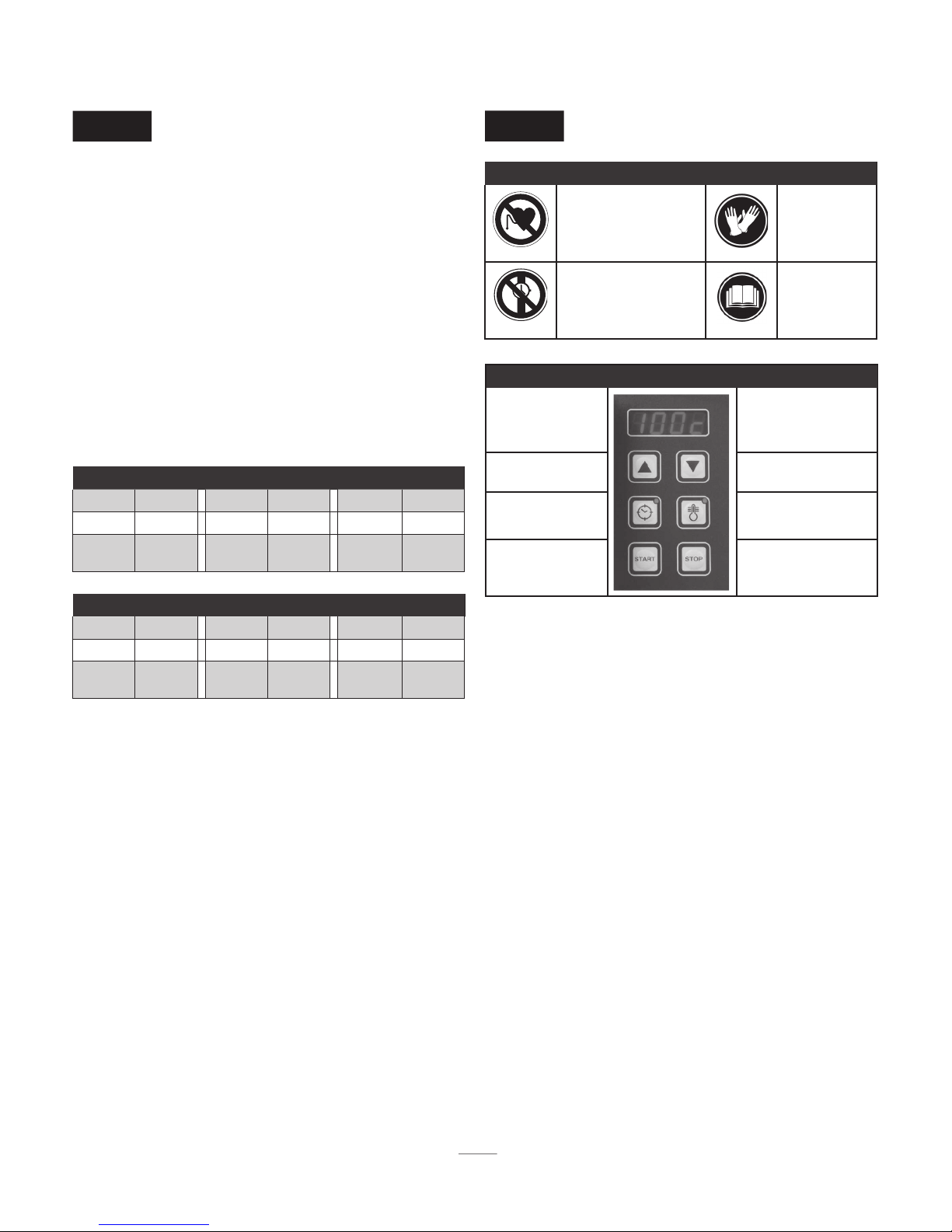
There are two modes of heating:
Using theTemperature Mode
(Default mode whenever the machine is switched on)
• Set up the work piece and probe according to the
instructions in sections 5 & 6.
• Switch the machine on.The display will show 100º C (or 100º
F). Enter the desired temperature to which the work piece
will be heated up to using the ‘▲’ or ‘▼’ key (by pressing the
temperature mode key () you can choose between steps of
1º or 10º - this is the same whether working in C or F).
• Press the ‘START’ key. Heating starts and a soft buzzing sound
will be heard.
• The current temperature of the work piece appears on the
display. When the desired temperature has been reached,
the display starts to blink and a loud beeping is emitted.
Unless you press the ‘STOP’ key, the heat-retention function
will keep the bearing at that temperature for 5 minutes.The
machine resumes heating after a temperature drop of 3º (C
or F).When the set temperature is reached once more the
induction heater emits a loud beep. Press the ‘STOP’ key to
switch off the machine.
• The heating process or the heat-retention function can be
interrupted at any time by pressing the ‘STOP’ key.
Using theTime Mode
• Set up the work piece and temperature probe according to
the instructions in sections 5 & 6 (the temperature probe
is only necessary if you want to check the temperature).
• Switch the machine on and press the time mode key ‘‘.
Press the ‘▲’ or ‘▼’ key to set the desired time (by pressing
the time mode key ‘‘ you can choose between steps of
one minute or one second).
• Press the ‘START’ key. Heating starts and a soft buzzing
sound will be heard.
• If the temperature key () is pressed while heating, the
current temperature is displayed for 3 seconds. After that
the countdown is resumed.
• During the heating process the set time runs to 00:00.
When 00:00 is reached the induction heater switches off.
The work piece is then automatically demagnetised and a
loud continuous beeping is emitted. Press the ‘STOP’ key
to switch off the machine.
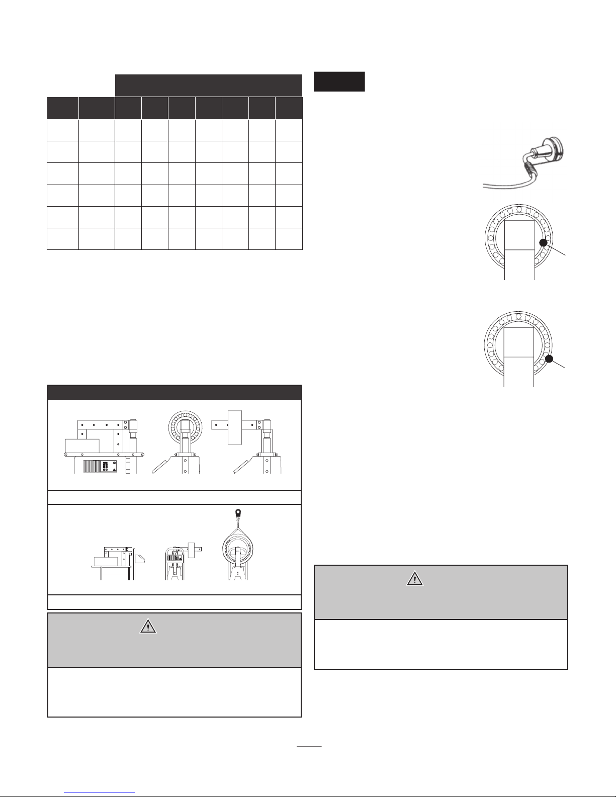
Work piece removal
• After pressing the ‘STOP’ key, place the probe on the side
of the vertical pole. Pressing the ‘STOP’ key always causes
the work piece to be automatically demagnetised.
• Using heat-resistant gloves, grip the yoke with the bearing
on it and place it on a clean, heat-resistant surface. Mount
the bearing immediately to prevent cooling. If using a
model with a swing arm, swivel the yoke with the bearing
on it into the fixed, open position (at 45º). Slide the bearing
from the yoke. Mount the bearing immediately to avoid
heat loss.
Malfunctioning
• If the temperature of the work piece fails to increase by 1º
(either C orF) within a set time-span, the heater switches off
automatically. Four blinking dashes will appear (----) in the
display, and a loud intermittent beep is emitted. Press the
‘STOP’ key to stop the beeping and check whether:
• the probe is still attached to the work piece, and is
connected correctly into its socket.
• the probe wiring has been damaged.
• the probe surface is clean.
• the heater capacity is too small for the work piece.
If the probe is defective, the Time Mode can still be used.
The temperature should be checked using an external
thermometer.
• If a loud vibrating noise is heard, first check to see that the
contact surfaces of the yokes are greased sufficiently.Then
check to see that the yoke is making optimal contact with
poles. (To adjust yokes: Place yoke on heater, unscrew the
bolts in the yoke ¼ turn. Switch on heater and the yoke
will set itself. Re-tighten the bolts.You can also use a nylon
hammer as an aid to reposition the laminates).
Temperature Mode: Time Mode:
• Used for controlled heating up to
the desired temperature.
• Used when you wish to keep
the work piece at the desired
temperature for up to 15 minutes.
• Suitable for batch production. If
the time taken to heat the work
piece to the desired temperature
is known.
• Emergency use if the
temperature probe is lost or
defective. The temperature
of the work piece should be
checked using an external
thermometer.