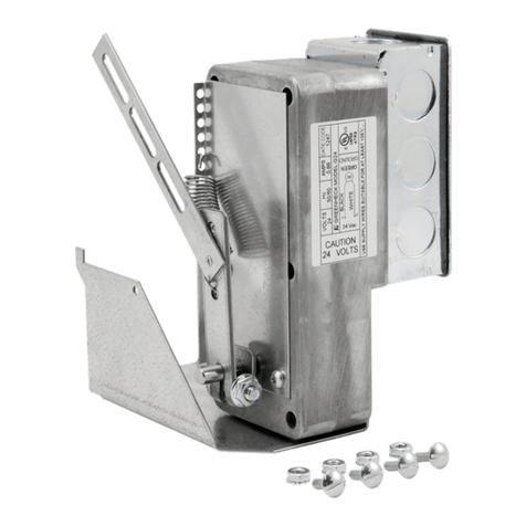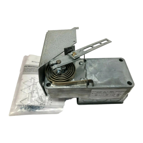
MP-210 Motor Pack2®
Installation Instructions
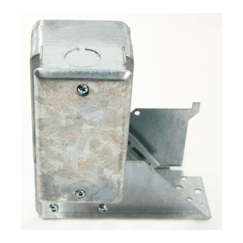
1. The MP-210 motor pack is designed for installation
on model WD-200 series backdraft dampers only.
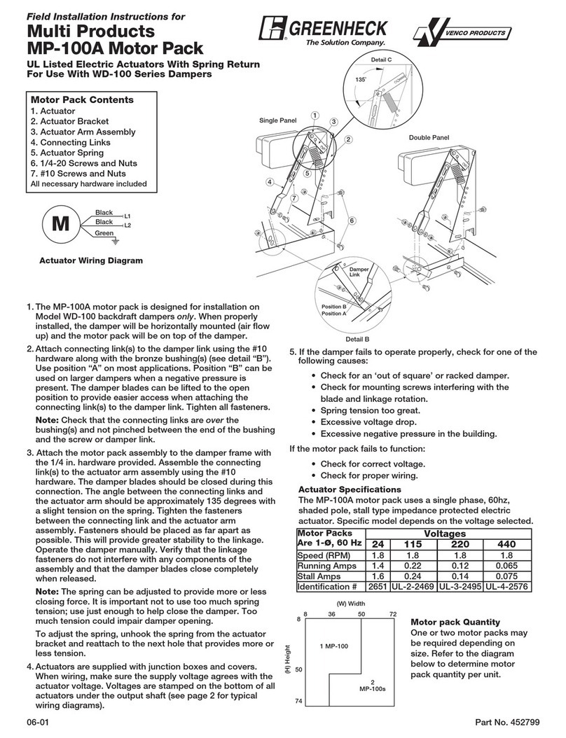
2. For single panel damper, insert tab of motor bracket
into the slot on the side of the frame. For dampers
with center bars, the tab of the motor bracket should
be inserted into the slot on the bottom of the center
bearing rail. Position bracket over the two holes on
the bottom of the frame and secure with the hardware
provided.
3. Loosely connect the actuator arm assembly to
the connecting link using the provided hardware.
Fasteners should be placed as far apart as
possible to provide greater stability to the linkage.
The connecting links may need to be modified or
shortened on some dampers sizes. To make the
adjustment easier, release the spring from the spring
adjustment bracket.
Note: The connecting link(s) have been installed
on the damper at the factory.
4. To adjust the actuator linkage, position the actuator
arm (attached to the damper) approximately 1⁄8in.
away from the rubber bumper. While holding the
damper blades closed, tighten the fasteners between
the connecting link and actuator arm assembly.
Place the spring onto the first hook of the adjustment
bracket (see figure on page 1). Operate the damper
manually. Verify that the linkage and fasteners do
not interfere with any components of the assembly
and that the damper blades close completely when
released. To increase spring tension, move the spring
to the next hook as shown on page 1.
Note: It is important to avoid too much spring
tension; use just enough tension to close the
damper. Too much tension could impair opening of
the damper or cause damage to the components
as the crank arm impacts the rubber bumper.
5. Actuators are supplied with junction box and cover.
When wiring, make sure the supply voltage agrees
with the actuator voltage. On dual voltages motor
packs, be sure to connect the proper motor leads
for the correct voltage and insulate any unused wire.
The voltage of each specific model is indicated on a
label that is affixed to the actuator (see typical wiring
diagrams).
6. If the damper fails to open properly, check for one of
the following causes:
• Check for an ‘out of square’ or racked damper
• Check for mounting screws interfering with the
blade and linkage rotation
• Spring tension too great
• Excessive voltage drop
• Excessive negative pressure in the building
If actuator fails to function:
• Check for correct voltage
• Check for proper wiring
Motor Pack Quantity
More than one motor pack may be required depending
on damper size:
• On single panel dampers, the actuator is
installed as shown on page 1 in the single
panel view
• On double or triple panel dampers, the
actuator(s) is installed as shown on page 1
in the multiple panel view.
Actuator Specifications
MP-210 motor pack uses a single phase shaded pole
stall type impedance protected electric actuators and
are supplied in various voltages (see chart). For 277,
380, 575, or 600 volt operation a transformer and 120V
motor pack is required.
Motor Packs Stall Amps Spec ID#
24V (50/60 Hz) .66 G24
110 - 120V
(50/60 Hz) .15 G110-240
208 - 240V
(50/60 Hz) .07 G110-240
460V (60 Hz) .041 G460
