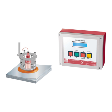
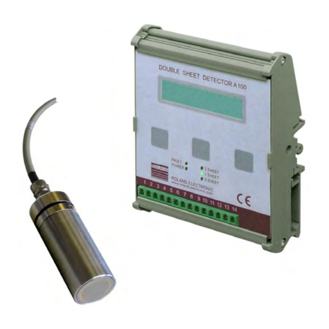
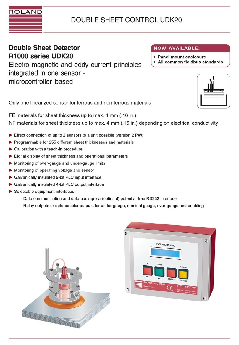
Roland Double Sheet Detector I100 User manual

Double Sheet Detector I100 R100 Series
Double Sheet Detector I100
R100 Series
Pos: 1 /Doppelblech/ Geräte/R100/Deckbla tt/Deckblatt für Handbuc h I100 @ 0\mod_1185792228 562_501.doc @ 4414
for double sided sensors
► Double sided sensors (transmitter / receiver), inductive
► Non-contact double sheet control of
FE material 0.05 - 4 mm (single sheet)
NF material 0.05 - 12 mm (single sheet)
► Suitable for fluttering sheets
► Easy setup by key operation or via control input
► LCD display for visualization of nominal / current values,
operational / error messages, key allocation
► Compact enclosure
- control unit for DIN-rail mounting, protection class IP00
- control unit for screw-on mounting, pluggable connections, protection class IP54
- control unit for screw-on mounting, in protective enclosure, protection class IP65

Copyright
© 2013 ROLAND ELECTRONIC GmbH
Otto-Maurer-Str. 17
DE 75210 Keltern
All rights on this document are at Roland Electronic GmbH.
Reproduction (also partly), electronical coverage, translation, transmission to third parties,
only with our prior permission.
Subject to change without further notice.
===== Ende der Stückliste == ===

Manual
Double Sheet Detector R100 I100
for pairs of sensors
B0003308 / 1.4 /
13.02.2013 Table of contents
ROLAND ELECTRONIC GmbH · Otto-Maurer-Str. 17 · DE 75210 Keltern · Phone +49 (0)7236-9392-0 · Fax +49 (0)7236-9392-33 3
Declaration of conformity according to EC directives .....................................................................................5
1Safety advices ........................................................................................................................................7
1.1 General..............................................................................................................................................7
1.2 Safety instructions and warnings for user .........................................................................................7
2Technical data ........................................................................................................................................9
2.1 Control unit I100................................................................................................................................9
2.2 S/E sensors.....................................................................................................................................12
2.2.1 Sensor S/E 28.............................................................................................................................12
2.2.2 Sensor S/E 34.............................................................................................................................12
2.2.3 Sensor S/E 34V_16kHz ..............................................................................................................12
2.2.4 Sensor S/E 54.............................................................................................................................12
2.2.5 Sensor S/E 75.............................................................................................................................12
2.2.6 Sensor MSI18S/E .......................................................................................................................12
2.3 Technical drawing S/E sensors.......................................................................................................13
2.3.1 Sensor diagrams.........................................................................................................................14
2.3.2 Cable allocation of S/E-sensors and sensor cables KISS and KISE..........................................15
2.3.3 Cable allocation of MSI18S/E-sensors and cables KMSISS and KMSISE ................................16
3System description..............................................................................................................................17
3.1 Introduction .....................................................................................................................................17
3.2 Structure and measuring principle ..................................................................................................17
3.3 Functional sequence.......................................................................................................................18
4Mounting...............................................................................................................................................19
4.1 Mounting of the control unit.............................................................................................................19
4.2 Mounting of the sensors..................................................................................................................19
4.2.1 Mounting the MSI18S/E-sensors................................................................................................20
4.2.2 Measurement target....................................................................................................................21
4.3 Cables .............................................................................................................................................22
4.3.1 Sensor cables .............................................................................................................................22
4.3.2 Power supply / Control cables ....................................................................................................22
5Electrical installation ...........................................................................................................................23
5.1 Connecting diagram for I100 and I100-IP65...................................................................................24
5.2 Connecting diagram for MSI18S/E-sensors....................................................................................25
5.3 Connections at I100-S.....................................................................................................................26
6Start-up..................................................................................................................................................29
6.1 Keys and indicators.........................................................................................................................29

Manual
Double Sheet Detector R100 I100
for pairs of sensors
Table of contents B0003308 / 1.4 / 13.02.2013
4 ROLAND ELECTRONIC GmbH · Otto-Maurer-Str. 17 · DE 75210 Keltern · Phone +49 (0)7236-9392-0 · Fax +49 (0)7236-9392-33
6.2 Allocation and function of keys....................................................................................................... 29
6.3 Switching on and Powering up....................................................................................................... 30
6.4 Operational conditions.................................................................................................................... 30
6.4.1 Undisturbed operation................................................................................................................ 30
6.4.2 Detection of 0-sheet, 1-sheet or 2-sheet.................................................................................... 30
6.4.3 Operational disturbances ........................................................................................................... 31
6.4.4 Functional check ........................................................................................................................ 31
6.5 Measurement mode ....................................................................................................................... 32
6.6 Teach-In ......................................................................................................................................... 33
6.7 Changing the switching thresholds................................................................................................. 34
6.8 Teach-In with changed threshold values........................................................................................ 36
6.9 External Teach-In ........................................................................................................................... 37
7Fault messages, causes and remedies.............................................................................................39
8Maintenance......................................................................................................................................... 41
9Order data ............................................................................................................................................ 43

Manual
Double Sheet Detector R100 I100
for pairs of sensors
B0003308 / 1.4 /
13.02.2013 Safety advices
ROLAND ELECTRONIC GmbH · Otto-Maurer-Str. 17 · DE 75210 Keltern · Phone +49 (0)7236-9392-0 · Fax +49 (0)7236-9392-33 5
Pos: 1 /Komponenten allge mein/Leerseite @ 0\mod_1 165223317234_501. doc @ 2343 @
Pos: 2 /Komponenten allge mein/2-EG Konformi tätserklärung 24V DC @ 0\ mod_1173707433093_501. doc @ 3832 @
Declaration of conformity according to EC directives
Manufacturer: Roland Electronic GmbH
Otto-Maurer-Str. 17
DE 75210 Keltern
Product name: I100
Product type: R100 Double Sheet Detector
Roland Electronic GmbH declare that the product listed above complies with the requirements of
the EMC directives listed below.
Applied Directives:
2004/108/EG: EMC Directive
EN61000-6-2: 2005-08 EN61000-6-4: 2007-01
Date of mark’s apposition: 13.02.2013
Keltern, 13.02.2013 Managing Director
Place, Date Signature Function of the signer
The declaration confirms the compliance with the cited directives. However, it is not any implied warranty of fitness for a
particular purpose especially as it may relate to product liability.
The safety instructions and warnings must be observed.
DIN EN ISO 9001
Reg.-no. 5152
Pos: 3 /Komponenten allge mein/Leerseite @ 0\mod_1 165223317234_501. doc @ 2343 @

Manual
Double Sheet Detector R100 I100
for pairs of sensors
Safety advices B0003308 / 1.4 / 13.02.2013
6 ROLAND ELECTRONIC GmbH · Otto-Maurer-Str. 17 · DE 75210 Keltern · Phone +49 (0)7236-9392-0 · Fax +49 (0)7236-9392-33
Blank page
Pos: 4 /Kapitelübersic ht/01. Sicherhei tshinweise @ 0\mod_1121421 059859_501.doc @ 505 @

Manual
Double Sheet Detector R100 I100
for pairs of sensors
B0003308 / 1.4 /
13.02.2013 Safety advices
ROLAND ELECTRONIC GmbH · Otto-Maurer-Str. 17 · DE 75210 Keltern · Phone +49 (0)7236-9392-0 · Fax +49 (0)7236-9392-33 7
1 Safety advices
Pos: 5 /Doppelblech/ Geräte/R1002/1 Sicher heitshinweise/A llgemeines zu diesem Doku ment @ 0\mod_1184842595390_5 01.doc @ 4065 @
1.1 General
This document was created with utmost care. Anyhow, faults and cases of misunderstanding
cannot be totally excluded. Please contact us in case of differences or weak understanding. We will
be pleased to assist you.
We reserve the right to improve this document at any time without announcement. No exchange of
delivered documents.
Pos: 6 /Komponenten allge mein/Sicherheitshin weise R1000 @ 0\mod_112 7211035609_501.doc @ 613 @
1.2 Safety instructions and warnings for user
This handbook contains all information required for the correct operation of the Roland equipment.
It has been written for technically qualified personnel.
Unauthorized tampering with the unit, especially ignoring the warnings in this handbook, can cause
malfunction and damage to the unit. Only authorized personnel should be allowed to make
changes to the unit and perform cable connections especially the power supply.
Should it be necessary, e.g. in case of service or repair, to make measurements within the unit,
then all customary accidents prevention procedures should be observed. Only professional
electrical tools should be used.
Note The factory pre-settings – especially the upper / lower limit values – have
been chosen such that an optimal machine protection is ensured.
Diverging settings can impair the machine protection.
Safety advice for persons with cardiac pacemakers!
Persons with cardiac pacemakers are to stay away from the sensors!
The strong magnetic / electromagnetic fields of the sensors can cause malfunction
of cardiac pacemakers and other such apparatus!
Pos: 7 /Kapitelübersic ht/02. Technische Date n @ 0\mod_1121421119875_5 01.doc @ 506 @

Manual
Double Sheet Detector R100 I100
for pairs of sensors
Safety advices B0003308 / 1.4 / 13.02.2013
8 ROLAND ELECTRONIC GmbH · Otto-Maurer-Str. 17 · DE 75210 Keltern · Phone +49 (0)7236-9392-0 · Fax +49 (0)7236-9392-33
Blank page

Manual
Double Sheet Detector R100 I100
for pairs of sensors
B0003308 / 1.4 /
13.02.2013 Technical data
ROLAND ELECTRONIC GmbH · Otto-Maurer-Str. 17 · DE 75210 Keltern · Phone +49 (0)7236-9392-0 · Fax +49 (0)7236-9392-33 9
2 Technical data
Pos: 8 /Doppelblech/ Geräte/R100/3 Technisc he DatenAuswertegerät I 100 @ 0\mod_118485322553 1_501.doc @ 4200 @
2.1 Control unit I100
Supply voltage 24 V DC / 110 mA
Power consumption approx. 2 VA
Fuse 375 mA slow-blow size 1206 (SMD)
Power / switching indication 5 LEDs
Display LCD display, 2 lines, 16 chars. each
Ambient temperature 0° - 50°C (32° - 122°F) during operation
Switching outputs 0-1-2 - Sheet Opto coupler outputs, output sourcing (PNP)
Temperature depending drift of switching point ± 0,02 % / °C
Switching capacity max. 50V, max. 10mA
Measurement period The min. dwell time of the sheet between the sensors roughly
equals the sensor diameter in milliseconds, e.g. for S28 = 30 ms..
Enclosure for DIN-rail mounting (EN50022, BS5584)
Class of protection I100 / I100-S / I100-IP65 IP00 / IP54 / IP65
Weight approx. 0,2 kg (0.44 lbs)
Connections Terminal block (I100 / I100-IP65) / Plug connection (I100-S)
Dimensions 125,4 × 103 × 38 mm (H × W × D)
125
,
4
46,5
103
fault
power 2 sheet
1 sheet
0 sheet
Fig. 1: Dimensions of I100 (for mounting on DIN-rail) I100 abmessungen.wmf

Manual
Double Sheet Detector R100 I100
for pairs of sensors
Technical data B0003308 / 1.4 / 13.02.2013
10 ROLAND ELECTRONIC GmbH · Otto-Maurer-Str. 17 · DE 75210 Keltern · Phone +49 (0)7236-9392-0 · Fax +49 (0)7236-9392-33
Description
1 Screw fitting M16
for control cable
Wrench size 19 mm
2 Screw fitting M12
for sensor cable (transmitter)
Wrench size 15 mm
3 Screw fitting M12
for sensor cable (receiver)
Wrench size 15 mm
120
114
90,5
135
154
148
160
35
38
31 2
9
0
3040
M16×1,5
SW 19
M12×1,5
SW 15
M12×1,5
SW 15
Deckel / Lid
63
fault
power 2 sheet
1 sheet
0 sheet
4,2 Ø
Fig. 2: Dimensions of I100-IP65 (in protective enclosure IP65) I100 in multibox IP65.wmf

Manual
Double Sheet Detector R100 I100
for pairs of sensors
B0003308 / 1.4 /
13.02.2013 Technical data
ROLAND ELECTRONIC GmbH · Otto-Maurer-Str. 17 · DE 75210 Keltern · Phone +49 (0)7236-9392-0 · Fax +49 (0)7236-9392-33 11
Description
To connect the connection
cables a clearance of 120mm
is required.
155
137
122
130
105
73,5
Ø4,5mm
29
Freiraum für
Kabel und Stecker
Clearance for
Cables and plugs
120
37
8
Fig. 3: Dimensions of I100-S
Pos: 9 /Doppelblech/ Sensoren/S/E-Sensoren/ S/E-Sensoren Techn. Daten @ 0\mod_118535038709 3_501.doc @ 4368 @

Manual
Double Sheet Detector R100 I100
for pairs of sensors
Technical data B0003308 / 1.4 / 13.02.2013
12 ROLAND ELECTRONIC GmbH · Otto-Maurer-Str. 17 · DE 75210 Keltern · Phone +49 (0)7236-9392-0 · Fax +49 (0)7236-9392-33
2.2 S/E sensors
The sensors are available either with fixed cable or plug connector.
The pluggable version has the addition S (e.g. S/E28 -> S/E28S)
For all sensors: Class of protection: IP65
Length: transmitter 65 mm, receiver 45 mm
Ambient temperature: 0 – 50 °C during operation)
Single sheet thickness: see sensor diagrams
2.2.1 Sensor S/E 28
Technical data
Responding time: 30 ms
Diameter: 28 mm (1.1 inch)
Weight: 0,28 kg (0.62 lbs)
2.2.2 Sensor S/E 34
Technical data
Responding time: 35 ms
Diameter: 34 mm (1.34 inch)
Weight: 0,40 kg (0.89 lbs)
2.2.3 Sensor S/E 34V_16kHz
Technical data
Responding time: 35 ms
Diameter: 34 mm (1.34 inch)
Weight: 0,40 kg (0.89 lbs)
2.2.4 Sensor S/E 54
Technical data
Responding time: 55 ms
Diameter: 54 mm (2.13 inch)
Weight: 0,90 kg (1.99 lbs)
2.2.5 Sensor S/E 75
Technical data
Responding time: 75 ms
Diameter: 75 mm (2.96 inch)
Weight: 1,80 kg (3.97 lbs)
2.2.6 Sensor MSI18S/E
Technical data
Responding time: 30 ms
Diameter: 18 mm (0.71 inch)
Weight: 0,18 kg (0.40lbs)
Pos: 10 /Doppelblech/ Sensoren/S/E-Sensor en/S/E-Sensoren Techn. Zeichnung @ 0\mod_118535 1937109_501.doc @ 4373 @

Manual
Double Sheet Detector R100 I100
for pairs of sensors
B0003308 / 1.4 /
13.02.2013 Technical data
ROLAND ELECTRONIC GmbH · Otto-Maurer-Str. 17 · DE 75210 Keltern · Phone +49 (0)7236-9392-0 · Fax +49 (0)7236-9392-33 13
2.3 Technical drawing S/E sensors
Description
The sensors S/E28, S/E34,
S/E54, S/E75 are equipped with a
firmly connected cable for terminal
connection. Standard cable length
is 2 meters, lengths up to 20
meters upon order.
The sensors S/E28S, S/E34S,
S/E54S, S/E75S are without
cable, but with build-in plug at the
sensor.
The sensors MSI18S and MSI18E
are without cable, but with build-in
plug at the sensor.
65 mm
Sender
Transmitter
45 mm
Empfänger
Receiver
Ø75 Ø54 Ø34 Ø28
Ø 20
Ø M18
52,5
75
10
MSI18S/E
Fig. 4: Dimensions of S/E sensors and MSI18S/E sensors Maßbild Sensoren SE28 bis SE75.wmf
Pos: 11 /Doppelblech/ Sensoren/S/E-Sensor en/S/E-Sensoren Sen sordiagramme @ 0\mod_118 5352736750_501.doc @ 4378 @

Manual
Double Sheet Detector R100 I100
for pairs of sensors
Technical data B0003308 / 1.4 / 13.02.2013
14 ROLAND ELECTRONIC GmbH · Otto-Maurer-Str. 17 · DE 75210 Keltern · Phone +49 (0)7236-9392-0 · Fax +49 (0)7236-9392-33
2.3.1 Sensor diagrams
The marked areas represent the working ranges of the sensors. For all combinations of sheet
thickness and sensor distance Ax within the range a double sheet condition will be securely
detected, if the switching thresholds are set “tight”. So it might be required to restrict the 1-sheet
detection range by changing the (factory-set) thresholds of 85% / 115% to approx. 95% / 105%.
The working ranges of the sensors depend very much on the material properties, they can deviate
from the sensor diagrams shown below.
0246810121415
S/E75
mm
Blechdicke
Sheet thickness
A
x
30
40
50
60
mm
AL
FE
mm
15
10
5
0123
S/E28
mm
Blechdicke
Sheet thickness
Ax
AL
mm
10
20
30
40
123456
0
S/E34
mm
Blechdicke
Sheet thickness
Ax AL
FE
mm
10
20
30
40
246810
0
S/E54
mm
Blechdicke
Sheet thickness
Ax AL
FE
40
30
20
10
12345
0
S/E34V
mm
mm
Blechdicke
Sheet thickness
A
x
Nicht magnetischer
Edelstahl (INOX)
Non-magnetic
Stainless steel (INOX)
01
1,5 22,5 mm
Blechdicke
Sheet thickness
20
30
40
mm
MSI18E/S (5KHz)
AL
Ax
Fig. 5: Sensor diagrams for S/E sensors and MSI18S/E sensorsensordiagramme-S28-S75-deu-eng.wmf
Pos: 12 /Doppelblech/ Kabel/S/E-Sensoren Kab elbelegung @ 0\mod_118 5353919531_501.doc @ 4383 @ 33

Manual
Double Sheet Detector R100 I100
for pairs of sensors
B0003308 / 1.4 /
13.02.2013 Technical data
ROLAND ELECTRONIC GmbH · Otto-Maurer-Str. 17 · DE 75210 Keltern · Phone +49 (0)7236-9392-0 · Fax +49 (0)7236-9392-33 15
2.3.2 Cable allocation of S/E-sensors and sensor cables KISS and KISE
For sensors and cables before February 2008
1×2×0,25mm (pair-wise twisted)
2
KISS
KISE
S…
Transmitter
E…
Receiver
S…S
Transmitter
E…S
Receiver
brow
n
white
blank (shield)
blank (shield) [3
]
white [2]
brown [1]
white [3]
blank (shield)
brown [1]
brown
white
blank (shield)
1×2×0,25mm (pair-wise twisted)
2
1×2×0,25mm (pair-wise twisted)
2
1×2×0,25mm (pair-wise twisted)
2
F
or sensors and cables before
F
ebruary 2008
Fig. 6: Cable allocation of S/E sensors and sensor cables before february 2008 Kabelbelegung_SE-
Sensoren_deu.wmf
Note: S/E sensors with black cables should no longer be used.
For sensors and cables after February 2008
S…
Transmitter
E…
Receiver
S…S
Transmitter
E…S
Receiver
For sensors and cables after February 2008
KISS
KISE
brown
blank (shield
)
white
green
brown
white
blank (shield
)
brown (1)
blank (shield
)
white (2)
green (3)
brown (1)
white (3)
blank (shield
)
3×0,25mm
2
2×0,25mm
2
3×0,25mm
2
2×0,25mm
2
Fig. 7: Cable allocation of S/E sensors and sensor cables after February 2008 Kabelbelegung_SE-Sensoren_deu.wmf

Manual
Double Sheet Detector R100 I100
for pairs of sensors
Technical data B0003308 / 1.4 / 13.02.2013
16 ROLAND ELECTRONIC GmbH · Otto-Maurer-Str. 17 · DE 75210 Keltern · Phone +49 (0)7236-9392-0 · Fax +49 (0)7236-9392-33
2.3.3 Cable allocation of MSI18S/E-sensors and cables KMSISS and KMSISE
KMSISS-G
3
2
1
MSI18S
KMSISE-G
21
4
5
3
optional with straight receptacle or
right angle receptacle
1 = white
2 = green
3= brown
1 = white
2 = green
3 = brown
4 = yellow
5 = shield
MSI18E
Fig. 8: Cable allocation of MSI18S/E-sensors and sensor cables
Pos: 13 /Kapitelübersic ht/03. Systembesc hreibung @ 0\mod_112142115 0062_501.doc @ 507 @

Manual
Double Sheet Detector R100 I100
for pairs of sensors
B0003308 / 1.4 /
13.02.2013 System description
ROLAND ELECTRONIC GmbH · Otto-Maurer-Str. 17 · DE 75210 Keltern · Phone +49 (0)7236-9392-0 · Fax +49 (0)7236-9392-33 17
3 System description
Pos: 14 /Doppelblech/ Geräte/R1002/2 Syste mbeschreibung/I100/ Einführung @ 0\mod_11 84941239781_501.doc @ 4223 @
3.1 Introduction
When automatically feeding sheets from a stack to a processing machine, it can unintentionally
happen that more than one sheet is picked up and transported. This can result in disturbances of
the machine run, damage of tools, expensive repair measures and loss of production. The A100
double sheet detectors can reliably prevent from such incidents by measuring the thickness of
every sheet from both sides with a pair of sensors.
Pos: 15 /Doppelblech/ Geräte/R1002/2 Syste mbeschreibung/I100/ Aufbau und Messprinzip @ 0\mod_1185283890921 _501.doc @ 4343 @
3.2 Structure and measuring principle
A system mainly consists of the control unit, the sensor and the sensor cable.
For performing the measurement, the transporting facility of the machine must move the sheet
between the sensors. During the measurement the sensors do not contact the sheet.
The transmitter emits an alternating electrical field, the receiver on the other side of the sheet
electronically detects the signal attenuated by the sheet. The receiver signal is processed in the
control unit and made available to the machine control as switching signals.
The main influencing factors for the measurement are the material properties of sheets, the sensor
bracket (holder), the sensor distance and the neighbouring metal parts.
Caution! The system is not suited for applications
of personal protection!
Pos: 16 /Doppelblech/ Geräte/R1002/2 Syste mbeschreibung/I100/ Steuerungsablauf @ 0\ mod_1185283930328_501. doc @ 4349 @

Manual
Double Sheet Detector R100 I100
for pairs of sensors
System description B0003308 / 1.4 / 13.02.2013
18 ROLAND ELECTRONIC GmbH · Otto-Maurer-Str. 17 · DE 75210 Keltern · Phone +49 (0)7236-9392-0 · Fax +49 (0)7236-9392-33
3.3 Functional sequence
The transport facility places the sheet between the sensors. The receiving sensor will process the
transmitted sensor signal. According to the preset limits, the respective signal output
(0-sheet, 1-sheet, 2-sheet) will be set activated.
If the output signal for 2-sheet is active, the PLC stops the material transport for removal of the
double sheet.
Note! “Active“means, that the signalling output will switch. In case that the
supply voltage fails, all signalling outputs (0-, 1-, 2-sheet) will become
inactive.
Then the PLC must stop the material transport.
Caution! Usually, the signalling outputs of the control unit will be used for
stopping the material transport facilities and / or machines in case of
double sheet.
As soon as the double sheet is removed from the sensor(s), the
signalling outputs instantly switch back to normal condition (0-sheet /
1-sheet).
Suitable control measures must ensure that the previously stopped
material transport facilities and / or machines cannot automatically
restart and thus create hazardous situations.
Pos: 17 /Kapitelübersic ht/04. Montage @ 0\mod_ 1121421173015_501.doc @ 508 @

Manual
Double Sheet Detector R100 I100
for pairs of sensors
B0003308 / 1.4 /
13.02.2013 Mounting
ROLAND ELECTRONIC GmbH · Otto-Maurer-Str. 17 · DE 75210 Keltern · Phone +49 (0)7236-9392-0 · Fax +49 (0)7236-9392-33 19
4 Mounting
Pos: 18 /Doppelblech/ Geräte/R1002/4 Montage/ Montage des Gerätes AI 100 @ 0\mod_1184845853703_ 501.doc @ 4100 @
4.1 Mounting of the control unit
The system is available in 3 different enclosures:
• for machine mounting, cables pluggable, in metal enclosure,
protection class IP54.
• for DIN-rail mounting (EN50022, BS5584), protection class IP00.
• for machine mounting, in plastic enclosure with transparent lid,
protection class IP65.
The system should be mounted in such a way that the indicators and operating keys in the front of
the unit are always well visible. The place should be safely accessible and free from obstruction.
The system must not be exposed to extreme temperature, irradiation or mechanical load.
Pos: 19 /Doppelblech/ Geräte/R1002/4 Montage/ Montage der Sensoren I100 @ 0\mod_1185285231875 _501.doc @ 4355 @
4.2 Mounting of the sensors
Caution! The sensors must be kept away from magnet sensitive
media (cheque cards, hard disks, diskettes…) and
systems (cardiac pacemakers, solenoid switches).
Sensors with different sizes are available. The size has substantial influence on the thickness
measuring range.
Mounting:
The place of mounting depends on the transporting equipment. In principle a distance of more than
0.5m must be kept from magnetic/electromagnetic interference sources like e.g. valve coils,
transportation magnets, inductive proximity switches or the like.
The sensors can be mounted in any direction, transmitter and receiver must be aligned face-to-
face. The possible distance (Ax) of the sensors can be read from the sensor diagrams.
• It is recommended to mount the sensors in “stick-out” position in brackets made of plastic or
stainless steel.
• Flush mounting is also possible, then however only in brackets made of plastic material.
• Recessed installation is very unfavourable, particles and splinters can accumulate in the recess.
• Sensor brackets made of electrically well conductive NF metals (aluminum, copper, brass)
should not be used, since otherwise the sensor distances must be reduced (see sensor
diagrams).
Length and width of the sheet to be controlled should be at least 3 × the sensor diameter. Then
safe double sheet control is ensured.
The minimum retention time of the sheet between the sensors (full surface coverage) up to
switching the appropriate exit depends on the sensor diameter. The minimum retention time (in
milliseconds) corresponds roughly to the sensor diameter. Something similar applies to the
minimum measuring break between 2 sheet metals up to switching the appropriate exit.

Manual
Double Sheet Detector R100 I100
for pairs of sensors
Mounting B0003308 / 1.4 / 13.02.2013
20 ROLAND ELECTRONIC GmbH · Otto-Maurer-Str. 17 · DE 75210 Keltern · Phone +49 (0)7236-9392-0 · Fax +49 (0)7236-9392-33
4.2.1 Mounting the MSI18S/E-sensors
Preferably the sensors should be mounted either in sturdy plastic or nonmagnetic stainless steel
brackets.
The transmitter and receiver should be mounted aligned to each other with a sensor gap specified
in the documentation. Sensors should not be mounted flush in the bracket and recessed mounting
should also be avoided in order to prevent accumulation of metallic chips and dirt.
Protruded sensor mounting according to examples "A" or "B" is recommended. Brackets made of
aluminum or other nonferrous metal with high electrical conductivity should be avoided in order to
prevent performance degradation and reduction in sensor gap Ax.
Measuring legend:
D: sensor diameter
B: min. 10 mm
Ax: agreed sensor distance, see sensor diagram
BB Ax
D
BB Ax
D>D>D
Example A
Example B
Fig. 9: Mounting the MSI18S/E-sensors
This manual suits for next models
1
Table of contents
Other Roland Security Sensor manuals

Roland
Roland R1000 series E20 User manual

Roland
Roland R100 Series User manual

Roland
Roland udk20 User manual

Roland
Roland ZBX-540E User manual

Roland
Roland R1000 series E20 User manual

Roland
Roland R1000 series E20 User manual

Roland
Roland udk20 User manual

Roland
Roland Double Sheet Detector R1000 Series User manual

Roland
Roland R4000 User manual

Roland
Roland R1000 series E20 User manual