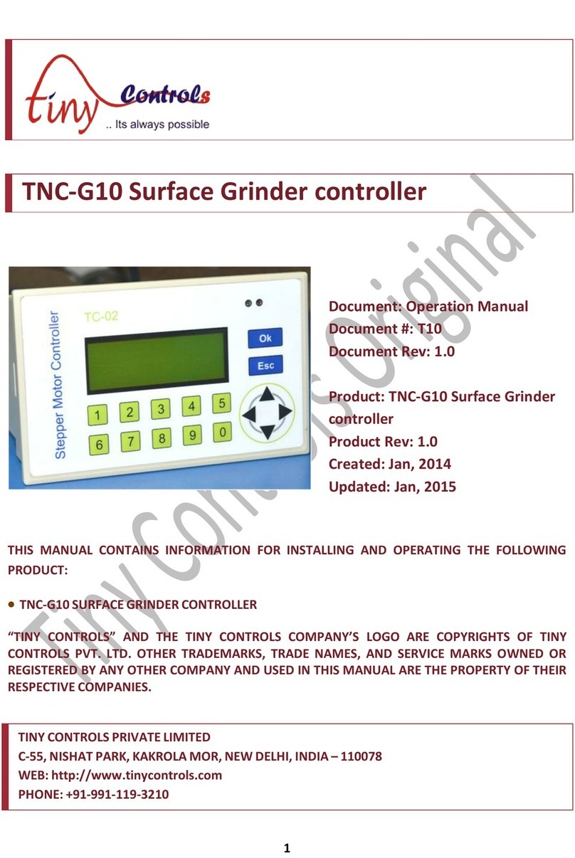
TINY TNC-M14-CNC User manual

1
TNC-M14-CNC CONTROLLER
Document: Operation Manual
Document #: TNC-M14-m
Document Rev: 1.0
Product: CNC controller
Product Rev: 1.0
Created: Oct-2013
THIS MANUAL CONTAINS INFORMATION FOR INSTALLING AND OPERATING THE
FOLLOWING PRODUCT:
TNC-M14- CNC CONTROLLER
“TINY CONTROLS” AND THE TINY CONTROLS COMPANY’S LOGO ARE COPYRIGHT OF
TINY CONTROLS (P) LTD. COMPANY. OTHER TRADEMARKS, TRADE NAMES, AND SERVICE
MARKS OWNED OR REGISTERED BY ANY OTHER COMPANY AND USED IN THIS MANUAL
ARE THE PROPERTY OF THEIR RESPECTIVE COMPANIES.
TINY CONTROLS PRIVATE LIMITED
C-55, NISHAT PARK, KAKROLA MOR, NEW DELHI, INDIA – 110078
WEB: http://www.tinycontrols.com
PHONE: +91-11-2533-1567, +91-991-119-3210

2
CONTENTS
1. SIGNS USED IN MANUAL 4
2. CNC CONTROLLER INCLUDES 6
3. MECHANICAL INSTALLATION 6
4. INTRODUCTION- TNC-M14- CNC CONTROLLER 7
5. FEATURES 8
6. CNC CONTROL BOARD SPECIFICATIONS 9
7. CNC CONTROLLER BOARD TERMINALS 10
8. CONNECTING OUTPUTS 11
9. CONNECTING INPUTS 13
10. CNC CONTROL BOARD CONNECTION WITH PEN DRIVE 15
11. CONNECTION DIAGRAM 16
12. AXES AND SPINDLE OUTPUTS CONNECTIONS WITH DRIVES 17
13. BLOCK MODE AND TOOL ZERO CONNECTIONS 18
14. HOME INPUTS CONNECTIONS WITH HOME SWITCHES 19
15. COOLANT, SPINDLE DRIVE AND VFD CONNECTIONS 19
16. LIMIT INPUTS CONNECTIONS WITH LIMIT SWITCHES 20
17. MOUNTING INSTRUCTIONS 21
18. INPUTS AND OUTPUTS SPECIFICATIONS FOR CONTROL BOARD 22
19. HAND HELD PENDANT 25
20. EMERGENCY BUTTON 28
21. BRIGHTNESS SETTINGS FOR LCD 28
22. KEYS FUNCTIONS IN VARIOUS MODES 29
23. CNC CONTROLLER BOARD CONNECTIONS WITH PENDANT 31
24. DESCRIPTION OF DISPLAYS IN VARIOUS STATES OF MACHINE 32
25. OPERATING THE CNC CONTROLLER 35
26. MAIN MENU 35
27. STRUCTURE TREE FOR MENU FUNCTIONS 36
28. GENERAL SETTINGS 37
29. ACTIVE PROFILE 41
30. AXIS SETTINGS 41
31. IO SETTING 44
a. SPINDLE SETTING 44
b. HOMING SETTING 46
c. HOME SWITCH SETTING 47
d. LIMIT SETTING 48
e. MISC OUTPUTS 49
32. TOOL SETTINGS 50

3
33. DATA FILE 52
34. DEFAULT PROFILES VALUES 54
35. KEY FUNCTIONS: NAVIGATION KEYS 55
36. NUMERIC KEYS 58
37. FEED RATE OVERRIDE AND SPINDLE SPEED OVERRIDE 59
38. G-CODE ALLOWED TO USE † 63
39. M CODES ALLOWED TO USE † 64
40. FORMAT OF A G-CODE LINE 65
41. TROUBLE SHOOTING 67
42. GLOSSARY 69
43. INDEX 71

4
SIGNS USED IN MANUAL
Warning:
A warning contains information, which is essential for avoiding a safety hazard.
Caution:
A caution contains information, which is necessary for avoiding a risk of damage to the product or other
equipment.
Note:
This icon indicates information which, if not heeded, can result in the CNC controller not operating to full
efficiency, as well as information concerning incorrect operations.
Tip:
This icon indicated information that can prove handy when performing certain settings or operations
with the equipment.
Application:
CNC controller may not be used for a life support system or other purposes directly related to the
human safety.
Although CNC controller is manufactured under strict quality control, install safety devices for
applications where serious accidents or material losses are foreseen in relation to the failure of it.
Installation:
Install the control board on a non inflammable material such as metal.
Don’t place inflammable matter nearby.
Prevent lint, paper, fibers, sawdust, dust, metallic dust or other foreign material from getting
accumulating onto the control board.
Don’t install or operate the CNC controller that is damaged or lacking parts. Doing so causes fire,
accidents or injuries.
Wiring:
Be sure to connect the grounding wires.
Qualified operators should carry out the whole wiring process.
Be sure to perform wiring of whole system after turning the power off.
Generally control signal wires are not reinforced insulation. If they accidently touch any of the live
parts in the main circuit, their insulation coat may break for any reasons. In such a case, an extremely
high voltage may be applied to the signal lines. Make a complete remedy to protect the signal line from
contacting any hot high voltage lines.
The wiring and the motors generate electric noise. Take care of malfunction of the nearby devices. To
prevent the motor from malfunctioning, implement noise control measures.
Operation
Don’t operate the switches with wet hands.
Although the hand pendant has an emergency button, install an emergency button separately along
with mounting of control board.

5
Don’t turn the main circuit power on or off in order to start or stop CNC controller operation.
In general, sheathes and covers of the control signal cables and wires are not specifically designed to
withstand a high electric field (i.e. reinforced insulation is not applied). Therefore, if a control signal
cable or wire comes into direct contact with a live conductor of the main circuit, the insulation of the
sheath or the cover might break down, which would expose the signal wire to a high voltage of the main
circuit. Make sure that the control signal cables and wires will not come into contact live conductors of
the main circuits.
Maintenance and Inspection, and Parts Replacement
Maintenance, inspection and parts replacement should be made only by qualified persons.
Take off the watch, rings and other metallic matter before starting the work.
Use insulated tools.
Others
Never attempt to modify the CNC control board or the handheld pendant device.
General Precautions
Drawing in this manual for the connections may be illustrated without the shield cover for explanation of the detail
parts. Restore the shields in the original state and observe the description in the manual before starting operation.
The ground terminal should be connected to the ground. And make sure to use the ground wires whose size is
greater than the power supply lines.
Be sure that Power supply should not be greater than 24 V; else it damages the Controller Board.
Caution is advised during the mechanical and electrical installation. Poorly tightened cables may
cause many problems; it’s also very difficult to detect such as defects while using the system. To avoid
the electric shock or equipment damage or burning of power cords, check loose connections or
exposed extension cords which may lead to tripping hazard.
Unplug the controller power supply and other connection when it is going to be left unused for an
extended period of time.

6
CNC CONTROLLER INCLUDES
1. Control Board
2. Handheld pendant
3. 3mm Serial cable connected to the pendant.
MECHANICAL INSTALLATION:

7
INTRODUCTION- TNC-M14-CNC CONTROLLER
CNC controller is a G-code programmable controller with step and direction outputs
for stepper drivers. The three axes X, Y and Z are linear whereas the 4th axis is
rotary and can be configured as either A, B or Caxis, providing flexibility to system.
All the four axes can be configured with independent adjustable maximum velocity
and acceleration. An isolated analog (0-10V) output is provided for VFD to control
spindle speed. Any two or all axes can be programmed for linear (line) interpolation,
any 2 axes can be interpolated for curve (circular) Interpolation or any 2 axes curve
with other axes line (helical) interpolation.
The USB host port provided is used to interface with a common pen (thumb) drive to
read and execute G-code files and doesn’t require a PC. There is no limit on G-
code file size. Controller can resume the operation on any power interruption saving
the current machine position, line of G-code and other status. Power up from
interrupted cycle offers to recover from power fail, automatically ‘homing’ the
machine, cursing to last location, and resuming from last saved line without losing a
beat in the process. Traditional complicated NC operation become easy and simpler
because of its user friendly interface.
Control board is the brain of CNC controller. It handles the command reading function
from pen drive and the serial transmission function with pendant. It controls the CNC
machine by giving outputs for steps and direction for stepper drives and spindle drive
and receiving Limit, tool zero, block input and home inputs.
All the axes and spindle outputs are buffered and taken out through screw terminals
from control board whereas all the inputs are optoisolated for noise immunity. A
provision for 6 buffered and 16 open collector outputs is given on the controller board
for other applications. These are termed as miscellaneous outputs and can be made
On/Off in G-code file.

8
FEATURES
1. Totally independent single board solution.
2. 32 digital + 2 analog + 1 isolated analog + 3 relay outputs.
3. 16 isolated inputs.
4. Low jitter 150 KHz Pulse rate on each axis.
5. Constant velocity (with look ahead) and exact stop path modes.
6. Interpolation – linear, arc and helical.
7. Work offset (work coordinates).
8. Feed override option (Feed and Spindle speed).
9. Tool offset option (auto tool offset measurement).
10. Jogging via inbuilt keypad (Step, continues and fast mode).
11. Feed hold (pause), Cycle start (and cycle resume), Cycle stop (abort).
12. Home and limit inputs for all axes (can be individually enabled/disabled).
13. Block execution mode (menu / run time control)
14. Controlled feed hold with deceleration to ensure no skipped steps and loss of
location.
15. G-code “check” option (Dry Run) and program limit check function.
16. Screw terminal connectors for connecting motor drive, input and outputs.
17. Help menu handy for first time users.
18. Handheld Pendent to display status/settings and control the machine.
19. Intuitive menus with easy to use smooth navigation.
20. Inputs for Limit and Home switches (or sensors).
21. Emergency Stop switch on handheld unit.

9
CNC CONTROL BOARD SPECIFICATIONS
Contents
Specifications
Processor
32 bit processor
Working coordinates
6 working coordinates
Display
20x4 alphanumeric LCD
USB Host Port
USB-2.0 Port
Communication Terminal 1
Serial Terminal for pendant
Communication Terminal 2
Serial Terminal (PLC interface)
File Format
8.3 format (8 lettered name+3 lettered extension
name)
Axes
4-axes
Interpolation function
Linear, curve, helical
Operating Interface
Friendly buttons & separate jog panel
Axes Drive Control type
Step/Dir (5V)
Max frequency of Step signal
150 KHz
Digital outputs
32
Digital inputs
20
Analog outputs (0-10 V) Isolated
1
Analog outputs (0-10 V) Non-Isolated
2
Relay outputs
3 (M3, M7, M8)
Interface Language
English
Supply voltage
24V DC
Max Power Consumption
24V/1A
Ambient temperature range
0˚-55˚ Celsius
Relative Humidity
< 90% (without condensation)
Dimensions
160x130
Weight
50g

10
CNC CONTROLLER BOARD TERMINALS
COM
NO
COM
NO
COM
NO
0V IN
0
-
10V ANALOG OUT
10V ANALOG IN
GND
5 V OUT
GND
12 V OUT
GND
24 V IN
X DIR OUT
X STEP OUT
COM
Y DIR OUT
Y STEP OUT
COM
Z DIR OUT
Z STEP OUT
COM
4 DIR OUT
4 STEPOUT
COM
SPINDLE DIR OUT
SPINDLE STEP OUT
GND
ANALOG OUT 1
(
0
-
10V
)
ANALOG OUT 2
(
0
-
10V
)
AGND
24 V
TOOL ZERO IN
BLOCK MODE IN
MISC INPUT 1
MISC INPUT 2
Misc Outputs 1-6
GND
24 V
X HOME IN
Y HOME IN
Z HOME IN
4 HOME IN
GND
24 V
X-LIMIT IN
Y-LIMIT IN
Z-LIMIT IN
4-LIMIT IN
GND
24 V
MISC INPUT 3
MISC INPUT 4
MISC INPUT 5
MISC INPUT 6
GND
1
2
3
J4
Misc Outputs 7
-
14
Misc Outputs 15-22
J3
J5
J2
SPINDLE
COOLANT MIST
COOLANT FLOOD
Connection to
Pendant
Pen drive slot

11
CONNECTING OUTPUTS
Digital Outputs: The digital outputs are as following:
a. OUTPUTS FOR SPINDLE DRIVE
a. Step output: 1
b. Direction output: 1
CNC controller board has a buffered step and
direction output for spindle drive. The step frequency
is user programmable and ranges up to 20 KHz.
These outputs can be disabled by disabling the
Spindle: Enable/Disable parameter in spindle
settings of IO settings function. Refer to IO settings
on page 44 for more details.
b. AXES OUTPUTS
a. Step outputs: 4
b. Direction outputs: 4
CNC Control board has Step/ Dir outputs for four axes
named X, Y, Z and 4th axis. These outputs are
buffered outputs and can be disabled by disabling
Drive: Enable/Disable parameter in Axis settings for
the axes which are not required in operation. Refer to
axes settings on page 41.
COM SELECTION JUMPER
User can change the COM signal configuration for axes outputs by changing the
position of jumper J4. By default, jumper, J4 is connected to position 2 and 3, COM is
grounded. To connect the COM to +5V, position the jumper at 1 and 2.
c. ANALOG 0-10V OUTPUT:
A 0-10V analog output signal directly goes to VFD to control the spindle. This circuit is
completely isolated from rest of control board.
If 10V input is fed from VFD to terminal 10V Analog IN; an analog output in range of
0-10V can be drawn from terminal 0-10V Analog OUT.
GND
SPINDLE STEP OUT
SPINDLE DIR OUT
COM
4 STEP OUT
4 DIR OUT
COM
Z STEP OUT
Z DIR OUT
COM
Y STEP OUT
Y DIR OUT
COM
X STEP OUT
X DIR OUT
COM

12
If 5V input is fed from VFD to 10V Analog IN, an analog
output in range of 0-5V can be drawn from terminal 0-10V
Analog OUT terminal.
d. SPINDLE ENABLE &COOLANT OUTPUTS:
Spindle NO output signal directly goes to VFD and
enables the spindle. Spindle NO is a relay output and the
relay switches to NO if spindle parameter is set enable in
IO Settings and spindle is made ON in Gcode.
Coolant mist NO and coolant flood NO are the relay
outputs and the relay switches to NO if these outputs are
made ON in the Gcode.
e. MISC OUTPUTS:
Misc outputs are miscellaneous outputs and 22 in
number. Required output can be made ON in G-code file.
Misc outputs 1-6 are buffered and the rest 16 are open
collector outputs. These can be made OFF collectively in
G-code file but are made ON individually using the
respective Mcode. The individual output terminals with its
respective Mcode are shown:
Figure shows the connector 5 outputs (see the terminal
diagram) with respective Mcode. These are 6 in number
and are buffered outputs. Enable/ Disable these outputs in
the MISC outputs function of IO settings and make them
ON/OFF in Gcode. These outputs can be set active high/
active low in the Misc outputs function.
However, for the buffered output pin, there isn’t any output if it is disabled in Misc
output function and made ON in Gcode.
Figure shows the connector 2 outputs with respective
Mcode. These are open collector outputs and can be
made ON/OFF in G-code. These outputs generate Active
high output when made ON in Gcode.
M54.03
M54.01
M54.05
M54.02
M54.06
M54.04
M54.07
M54.09
M54.13
M54.11
M54.08
M54.10
M54.12
M54.14
10 V ANALOG IN
0
-
10V ANALG OUT
0V IN
NO
COM
NO
COM
NO
COM
SPINDLE
COOLANT MIST
COOLANT FLOOD
J2
J5

13
Figure shows the connector 3 outputs with respective
Mcode. These are open collector outputs and can be
made ON/OFF in G-code. These outputs generate Active
high output when made ON in Gcode.
M54.01-M54.22: To make the Misc output ON.
M55.01-M55.22: To make the Misc output OFF.
M56: Execution of this Mcode switches OFF all the Misc outputs.
ANALOG OUTPUTS 1-2:
Two non-isolated analog 0-10V outputs are provided on
board. These are auxiliary outputs and can be set to any
value in range of 0-10V using Mcode 57 for output 1 and
Mcode 58 for output 2. The format of Mcode for these
outputs is:
M57 V2000: Generates 2000mV at analog output channel: 1
M58 V5000: Generates 5000mV at analog output channel: 2
M57 V0: Generates 0mV at analog output channel: 1
12V AND 5V OUTPUTS:
A 12V and 5V output can also be drawn from the
controller board. These two supply 100mA current and
remain active until the power continues to the board.
CONNECTING INPUTS
Inputs: The inputs are as following:
a. POWER SUPPLY
Connect a power supply of +24V DC at the input pin of CNC
controller board for its operation.
Limit inputs, home inputs, tool zero input, block mode input and all the miscellaneous
inputs are optoisolated.
AGND
ANALOG OUT2 0
-
10V
ANALOG OUT1 0
-
10V
GND
M54.16
M54.18
M54.20
M54.22
M54.15
M54.17
M54.19
M54.21
GND
+5 V OUT
GND
+12 V OUT
GND
+24 V IN
+24 V IN
GND
+12 V OUT
GND
+5 V OUT
GND
J3

14
b. TOOL ZERO INPUT:
An input signal is received on tool zero input pin when the
tool touches the sensor plate. Tool Zero IN terminal recieves
this signal by a wire whose other end is connected to the
tool by a clamp.
c. BLOCK MODE INPUT :
An external input is given to the block mode input pin of the
control board to execute the one line of G-code. In this
mode, the motion stops at the execution of one programmed
line and executes the next line on the trigger of an external
input on this pin.
c. HOMING INPUTS:
Homing inputs are input to “HOME IN” terminals of CNC
controller board from home switches of CNC machine for
respective axes. These inputs can be set as active high or
active low. Usually all the axes of CNC machine consists the
Home switch. Disable the home switch function in Home
Switch Settings menu for the axes which don’t have Home
switch or for the axes for which home switches aren’t
required.
d. LIMIT SWITCH INPUTS:
Just like home switches, CNC machine can or can’t have
limit switch. However, usually each axis of CNC machine
have two limit switches, one mounted in +ve direction and
other in –ve direction of axis. Axis limit input terminal shares
the inputs from both switches of same axis. The limit switch
can be set disabled if not required in limit settings function of
IO Settings. Disable the limit switch function in Limit settings
menu for the axes which don’t have the limit switch.
MISC INPUTS:Six terminals of misc inputs are provided on the board. Four input
terminals are used and the rest two inputs terminals are made for future development
24 V
TOOL ZERO IN
BLOCK MODE IN
MISC INPUT 1
MISC INPUT 2
GND
24 V
X HOME
IN
Y HOME IN
Z HOME IN
4
TH
HOME IN
GND
24 V
X LIMIT IN
Y LIMIT IN
Z LIMIT IN
4
TH
LIMIT IN
GND
24 V
MISC INPUT 3
MISC INPUT 4
MISC INPUT 5
MISC INPUT 6
GND

15
in board. These input terminals are Misc input terminal 3, 4, 5 and 6. And the function
assigned to them are Hold/ resume, stop, start and emergency resectively. These
functions are discussed further in manual.
CNC CONTROL BOARD CONNECTION WITH PEN DRIVE
Connect the USB flash drive to the USB slot on the control board as shown below:
The first LCD screen is displayed when the pen drive is detected by the controller.
The second screen is displayed when the pen drive is disconnected from the control
board.
Take care that the USB Flash drive should not be disconnected when the
program is running on the Gcode. Handle the pen drive carefully.
Connect the pen drive carefully. Reverse connections damages the pen drive.
Don’t connect the pen drive forcefully.

16
CONNECTION DIAGRAM
Tool Zero
Block zero
Z
-
Limit switch
X+ Limit switch
Y+ Limit switch
Y
-
Limit switch
X
-
Limit switch
4
-
Home switch
Z
-
Home switch
Y
-
Home switch
Coolant Mist
Coolant Flood
Z+ Limit switch
4+ Limit switch
4
-
Limit switch
X
-
Home switch
SPINDLE DIR
SPINDLE
STEP
GND
SPINDLE ON/OFF
GND
ANALOG OUT
ANALOG IN
GND
Power Supply 24 V
Connection to pendant
Power Supply to drive
Power Supply to drive
Power Supply to drive
Power Supply to drive

17
AXES AND SPINDLE OUTPUTS CONNECTIONS WITH DRIVES
X DIR OUT
X STEP OUT
COM
Y DIR OUT
Y STEP OUT
COM
Z DIR OUT
Z STEP OUT
COM
4
th
DIR OUT
4
th
STEP OUT
COM
SPINDLE DIR OUT
SPINDLE STEP OUT
Dir
Step
Gnd
SPINDLE DRIVER
GND

18
BLOCK MODE AND TOOL ZERO CONNECTIONS
CNC control board should be installed in dust free environment with suitable
temperature and humidity conditions. Read the CNC Controller Specification
table for these parameters.
Spindle motor
Collet
Sensor Plate
Clip holding wire
Tool
Shield wire
.
COM
NC
NO
Work bed
24 V
TOOL ZERO IN
BLOCK
MODE IN
MISC INPUT 1
MISC INPUT 2
GND

19
HOME INPUTS CONNECTIONS WITH HOME SWITCHES
COOLANT, SPINDLE DRIVE AND VFD CONNECTIONS
X HOME IN
Y HOME IN
Z HOME IN
4 HOME IN
.
COM
NC
NO
.
.
.
COM
NC
NO
COM
NC
NO
COM
NC
NO
X
-
HOME SWITCH
Y
-
HOME SWITCH
Z
-
HOME
SWITCH
4
th
-
HOME SWITCH
GND
10V ANOLOG IN
0
-
10V ANOLOG OUT
0V
-
IN
NO
COM
NO
COM
NO
COM
SPINDLE
COOLANT FLOOD
COOLANT MIST
Analog input
to
microcontroller
Analog input from microcontroller
Gnd
Spindle On/Off
Com
VFD
Coolant Flood
Coolant Mist
Shield wire
Shield wire

20
LIMIT SWITCHES CONNECTIONS WITH CONTROLLER BOARD
v
V
24V
X LIMIT IN
Y LIMIT IN
Z LIMIT IN
4
th
LIMIT IN
GND
.
.
.
.
.
.
.
.
COM
NC
NO
COM
NC
NO
COM
NC
NO
COM
NC
NO
COM
NC
NO
COM
NC
NO
COM
NC
NO
.
COM
NC
NO
Shield
wire
X+ LIIMIT SWITCH
X
-
LIIMIT SWITCH
Y+ LIIMIT SWITCH
Y
-
LIIMIT SWITCH
Z+ LIIMIT SWITCH
Z
-
LIIMIT SWITCH
4
th
+ LIIMIT SWITCH
4
th
-
LIMIT SWITCH
Table of contents
Other TINY Controllers manuals
Popular Controllers manuals by other brands

Grundfos
Grundfos BuildingConnect Installation and operating instructions
Emerson
Emerson Dixell iChill IC200D EVO Series Installing and operating instructions
Dungs
Dungs GasMultiBloc MB-D B01 Series instructions
Sentera Controls
Sentera Controls STVS1 Series Mounting and operating instructions
ADEMCO
ADEMCO 4180-12 Installation instructions manual

Hach
Hach SC4500 Basic user manual
