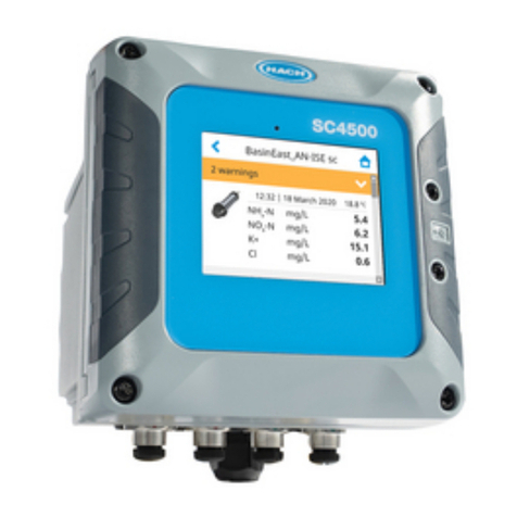
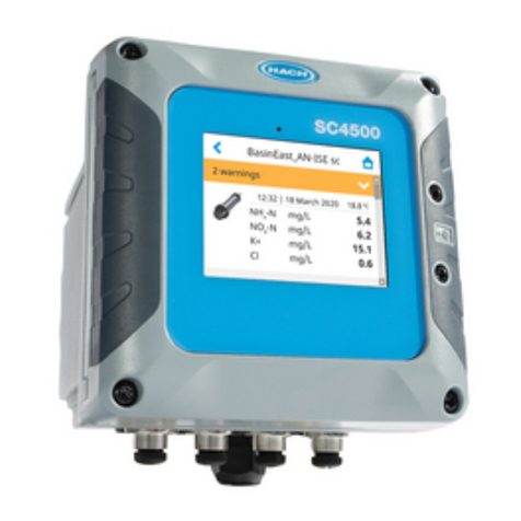
Hach SC4500 Quick manual

DOC023.98.90690
SC4500
11/2022, Edition 4
Basic User Manual
Allgemeines Benutzerhandbuch
Manuale di base per l'utente
Manuel d'utilisation simplifié
Manual básico del usuario
Manual básico do utilizador
Základní uživatelská příručka
Basishandleiding voor gebruikers
Grundlæggende brugervejledning
Podstawowy podręcznik użytkownika
Allmän användarhandbok
Peruskäyttöohje
Основно ръководство на потребителя
Alapvető felhasználói kézikönyv
Manual de utilizare de bază
Pagrindinis naudotojo vadovas
Базовое руководство пользователя
Temel Kullanıcı Kılavuzu
Základná používateľská príručka
Osnovni uporabniški priročnik
Osnovni korisnički priručnik
Βασικό εγχειρίδιο χρήστη
Põhijuhend
Osnovni korisnički priručnik

Table of Contents
English..............................................................................................................................3
Deutsch.......................................................................................................................... 25
Italiano............................................................................................................................ 49
Français......................................................................................................................... 72
Español.......................................................................................................................... 96
Português.................................................................................................................... 120
Čeština......................................................................................................................... 143
Nederlands................................................................................................................. 166
Dansk............................................................................................................................189
Polski............................................................................................................................ 212
Svenska....................................................................................................................... 235
Suomi............................................................................................................................257
български................................................................................................................... 280
Magyar......................................................................................................................... 305
Română....................................................................................................................... 329
lietuvių kalba...............................................................................................................352
Русский........................................................................................................................375
Türkçe...........................................................................................................................400
Slovenský jazyk......................................................................................................... 423
Slovenski..................................................................................................................... 446
Hrvatski........................................................................................................................ 469
Ελληνικά...................................................................................................................... 492
eesti keel..................................................................................................................... 516
Српски......................................................................................................................... 539
2

Table of Contents
1 Specifications on page 3
2 Online user manual on page 4
3 General information on page 4
4 Installation on page 8
5 User interface and navigation on page 21
6 Startup on page 22
7 Operation on page 22
8 Maintenance on page 23
9 Troubleshooting on page 24
Section 1 Specifications
Specifications are subject to change without notice.
Specification Details
Dimensions (W x H x D) ½ DIN-144 x 144 x 192 mm (5.7 x 5.7 x 7.6 in.)
Enclosure UL50E type 4X, IEC/EN 60529–IP 66, NEMA 250 type 4X
Metal enclosure with a corrosion-resistant finish
Weight 1.7 kg (3.7 lb) (Controller weight without optional expansion modules)
Pollution degree Environment: 4; instrument: 2
Overvoltage category II
Protection class I, connected to protective earth
Environmental conditions Indoor and outdoor use
Power requirements AC controller: 100–240 VAC ±10%, 50/60 Hz; 1 A (50 VA with 8W sensor load,
100VA with 28W sensor load)
DC controller: 18–28 VDC; 2.5 A (12W with 9W sensor load, 36W with 20 W
sensor load)
Operating temperature –20 to 60 °C (–4 to 140 °F) (8 W (AC)/9 W (DC) sensor load)
–20 to 45 °C (–4 to 113 °F) (28 W (AC)/20 W (DC) sensor load)
Linear derating between 45 and 60 °C (–1.33 W/°C)
Storage temperature –20 to 70 °C (–4 to 158 °F)
Relative humidity 0 to 95%, non-condensing
Altitude 3000 m (9842 ft) maximum
Display 3.5-inch TFT color display with capacitive touchpad
Measurement Two device, digital SC connectors
Relays (high voltage) Two relays (SPDT);
Wire gauge: 0.75 to 1.5 mm2 (18 to 16 AWG)
AC controller
Maximum switching voltage: 100–240 VAC
Maximum switching current: 5 A Resistive/1 A Pilot Duty
Maximum switching power: 1200 VA Resistive/360 VA Pilot Duty
DC controller
Maximum switching voltage: 30 VAC or 42 VDC
Maximum switching current: 4 A Resistive/1 A Pilot Duty
Maximum switching power: 125 W Resistive/28 W Pilot Duty
Analog inputs (optional)3One 0-20 mA (or 4-20 mA) analog input on each analog input module
One analog sensor input on each sensor module
Maximum of two analog inputs
English 3

Specification Details
Analog outputs (optional)3Five 0–20 mA (or 4-20 mA) analog outputs on each analog output module1
Digital communication
(optional)3Profibus DPV1 module, Modbus TCP, PROFINET module, EtherNet/IP™2 module
RTC module (optional) Contact sales or technical support for information.
Note: Only one RTC module can be installed on a controller at the same time.
Network connection3LAN version (optional): Two Ethernet connectors (10/100 Mbps), M12 female D-
coding connector; Cellular version and WiFi version (optional)4
USB port Used for data download and software upload. The controller records
approximately 20,000 data points for each connected sensor.
Compliance information CE. ETL certified to UL and CSA safety standards (with all sensor types), FCC,
ISED, KC, RCM, EAC, UKCA, SABS, CMIM, Morocco
Warranty 1 year (EU: 2 years)
Section 2 Online user manual
This Basic User Manual contains less information than the User Manual, which is available on the
manufacturer's website.
Section 3 General information
In no event will the manufacturer be liable for damages resulting from any improper use of product or
failure to comply with the instructions in the manual. The manufacturer reserves the right to make
changes in this manual and the products it describes at any time, without notice or obligation.
Revised editions are found on the manufacturer’s website.
3.1 Safety information
The manufacturer is not responsible for any damages due to misapplication or misuse of this product
including, without limitation, direct, incidental and consequential damages, and disclaims such
damages to the full extent permitted under applicable law. The user is soley responsible to identify
critical application risks and install appropriate mechanisms to protect processes during a possible
equipment malfunction.
Please read this entire manual before unpacking, setting up or operating this equipment. Pay
attention to all danger and caution statements. Failure to do so could result in serious injury to the
operator or damage to the equipment.
Make sure that the protection provided by this equipment is not impaired. Do not use or install this
equipment in any manner other than that specified in this manual.
3.1.1 Use of hazard information
D A N G E R
Indicates a potentially or imminently hazardous situation which, if not avoided, will result in death or serious injury.
WARNING
Indicates a potentially or imminently hazardous situation which, if not avoided, could result in death or serious
injury.
1Refer to the module documentation for additional information.
Note: Install only one module in one of the available slots.
2EtherNet/IP is a trademark of OVDA Inc.
3Dependent on controller configuration.
4An external USB box WiFi is necessary for network connection on WiFi versions. An external
USB box cellular is necessary for network connection on cellular versions.
4 English
CAUTION
Indicates a potentially hazardous situation that may result in minor or moderate injury.
N O T I C E
Indicates a situation which, if not avoided, may cause damage to the instrument. Information that requires special
emphasis.
3.1.2 Precautionary labels
Read all labels and tags attached to the instrument. Personal injury or damage to the instrument
could occur if not observed. A symbol on the instrument is referenced in the manual with a
precautionary statement.
This is the safety alert symbol. Obey all safety messages that follow this symbol to avoid potential
injury. If on the instrument, refer to the instruction manual for operation or safety information.
This symbol indicates that a risk of electrical shock and/or electrocution exists.
This symbol indicates the presence of devices sensitive to Electro-static Discharge (ESD) and
indicates that care must be taken to prevent damage with the equipment.
Electrical equipment marked with this symbol may not be disposed of in European domestic or public
disposal systems. Return old or end-of-life equipment to the manufacturer for disposal at no charge to
the user.
3.1.3 Compliance and certification
CAUTION
This equipment is not intended for use in residential environments and may not provide adequate protection to
radio reception in such environments.
Canadian Radio Interference-Causing Equipment Regulation, ICES-003, Class A:
Supporting test records reside with the manufacturer.
This Class A digital apparatus meets all requirements of the Canadian Interference-Causing
Equipment Regulations.
Cet appareil numérique de classe A répond à toutes les exigences de la réglementation canadienne
sur les équipements provoquant des interférences.
FCC Part 15, Class "A" Limits
Supporting test records reside with the manufacturer. The device complies with Part 15 of the FCC
Rules. Operation is subject to the following conditions:
1. The equipment may not cause harmful interference.
2. The equipment must accept any interference received, including interference that may cause
undesired operation.
Changes or modifications to this equipment not expressly approved by the party responsible for
compliance could void the user's authority to operate the equipment. This equipment has been tested
and found to comply with the limits for a Class A digital device, pursuant to Part 15 of the FCC rules.
These limits are designed to provide reasonable protection against harmful interference when the
equipment is operated in a commercial environment. This equipment generates, uses and can
radiate radio frequency energy and, if not installed and used in accordance with the instruction
manual, may cause harmful interference to radio communications. Operation of this equipment in a
English 5

residential area is likely to cause harmful interference, in which case the user will be required to
correct the interference at their expense. The following techniques can be used to reduce
interference problems:
1. Disconnect the equipment from its power source to verify that it is or is not the source of the
interference.
2. If the equipment is connected to the same outlet as the device experiencing interference, connect
the equipment to a different outlet.
3. Move the equipment away from the device receiving the interference.
4. Reposition the receiving antenna for the device receiving the interference.
5. Try combinations of the above.
3.2 Intended use
The SC4500 controller is intended for use by water treatment professionals who measure multiple
water quality parameters in industrial water, municipal water or waste water plants. The
SC4500 controller does not treat or alter water.
3.3 Product overview
D A N G E R
Chemical or biological hazards. If this instrument is used to monitor a treatment process and/or
chemical feed system for which there are regulatory limits and monitoring requirements related to
public health, public safety, food or beverage manufacture or processing, it is the responsibility of the
user of this instrument to know and abide by any applicable regulation and to have sufficient and
appropriate mechanisms in place for compliance with applicable regulations in the event of
malfunction of the instrument.
N O T I C E
Network and access point security is the responsibility of the customer that uses the wireless instrument. The
manufacturer will not be liable for any damages, inclusive however not limited to indirect, special, consequential
or incidental damages, that have been caused by a gap in, or breach of network security.
N O T I C E
Perchlorate Material—Special handling may apply. Refer to www.dtsc.ca.gov/hazardouswaste/perchlorate. This
perchlorate warning applies only to primary batteries (provided singly or installed on this equipment) when sold or
distributed in California, USA.
N O T I C E
The controller is supplied with a protection foil installed on the display. Make sure to remove the protection foil
before the controller is used.
The SC4500 is a 2-channel controller for digital analytical devices (e.g., sensors and analyzers).
Refer to Figure 1.
The controller shows sensor measurements and other data on the display, can transmit analog and
digital signals, and can interact with and control other devices through outputs and relays. Outputs,
relays, sensors and expansion modules are configured and calibrated through the user interface on
the front of the controller or remotely for network connected controllers. The controller connects to
Claros with a cellular network5, WiFi network5 or through LAN connection. The Prognosys diagnostic
system5 shows the status of maintenance tasks and gives the status of the instrument condition.
The instrument display is a touchscreen. The instrument enclosure has a protective vent in the
bottom. Do not cover or remove the protective vent. Replace the protective vent if damage is seen.
The controller is available with optional expansion modules. Refer to the expanded user manual on
the manufacturer's website for additional information.
6 English

Figure 1 Product overview
1 Label for module installation and wiring information 7 USB cover
2 USB connection for external USB box (WiFi or
cellular connection) 8 Electrical connections and fittings
3 Expansion module (Slot 0)59 Protective vent
4 Additional expansion module slots
(Slots 1, 2, 3 and 4) 10 Cover for module installation
5 Touchpad display 11 High-voltage barrier
6 USB connection for data download and firmware
update
5Dependent on controller configuration. The expansion modules are factory-installed based on
controller configuration.
English 7

3.4 Product components
Make sure that all components have been received. Refer to Figure 2. If any items are missing or
damaged, contact the manufacturer or a sales representative immediately.
Figure 2 Product components
1 SC4500 controller 7 Mounting foot (mounting bracket inserts) (2x)
2 Mounting hardware 8 Flat washer, ¼-inch ID (4x)
3 Sealing gasket for panel mount, Neoprene 9 Lock washer, ¼-inch ID (4x)
4 Vibration isolation gasket for pipe mount 10 Keps hexnut, M5 x 0.8 (4x)
5 Vibration isolation washer for pipe mount (4x) 11 Pan head screws, M5 x 0.8 x 15 mm (4x)
6 Bracket for wall and pipe mounting 612 Pan head screws, M5 x 0.8 x 100 mm (4x)7
Section 4 Installation
D A N G E R
Multiple hazards. Only qualified personnel must conduct the tasks described in this section of the
document.
6A bracket for panel mounting is available as an optional accessory. Refer to the expanded user
manual for replacement parts and accesories.
7Used for variable diameter pipe mount installations.
8 English

4.1 Installation guidelines
D A N G E R
Electrical shock hazard. Externally connected equipment must have an applicable country safety
standard assessment.
WARNING
Explosion hazard. This manual is only for installation of the unit in a non-hazardous location. For
installation of the unit in hazardous locations, use only the instructions and approved control drawing
provided in the hazardous location installation manual.
N O T I C E
Do not install the controller in an environment with a caustic atmosphere without a protective enclosure. A caustic
atmosphere will cause damage to electronic circuitry and components.
N O T I C E
Do not install the controller outdoors in an environment that receives direct sunlight or UV radiation or damage to
the controller can occur. Install the optional UV protection screen with sunroof to prevent damage from UV
exposure when installed outdoors in direct sunlight.
Note: (Network and Claros version only) Make sure that your IT department has approval for the installation and
commissioning of the device. Administrator rights are not necessary. The email address "[email protected]"
sends the setup email and "[email protected]" sends the system notifications that are necessary for the
installation. Add the two email addresses to the safe senders list to make sure to receive mails from these senders.
Hach does not send a request to confirm that the sender is not a robot.
• Install the controller in a location where the power disconnect device for the controller is easily
operated.
• Attach the controller upright and level on a flat, vertical surface.
• As an alternative, attach the instrument to a panel, vertical pole or horizontal pole.
• Make sure that the device is in a location where there is sufficient clearance around it to make
connections and to do maintenance tasks.
• Make sure that there is a minimum of 16 cm (6.30 in.) of clearance for the controller door to open.
• Install the instrument in a location with minimum vibration.
• The optional holder for mobile phones is recommended for all installations.
• The optional sunroof or the optional UV protection screen with sunroof is recommended for all
outdoor installations.
• Give protection to computers or other connected equipment that may not have equivalent
environmental ratings based on the enclosure rating of the equipment.
• Obey specified ambient ratings on the internal side of panels for panel mount installations.
• Make sure that the maximum power rating is correct for the ambient temperature.
4.2 Mechanical installation
4.2.1 Attach the instrument to a wall
Attach the controller upright and level on a flat, vertical surface. Make sure that the wall mounting is
able to hold 4 times the weight of the equipment. Refer to the illustrated steps in Figure 3 and
Product components on page 8 for the necessary mounting hardware.
English 9

Figure 3 Wall mounting
4.2.2 Attach the instrument to a pole
Attach the controller upright to a pole or pipe (horizontal or vertical). Make sure that the pipe diameter
is 19 to 65 mm (0.75 to 2.5 in.) Refer to the illustrated steps in Figure 4 and Product components
on page 8 for the necessary mounting hardware.
10 English

Figure 4 Pole mounting
4.2.3 Install the instrument in a panel
A rectangular hole is necessary for panel installation. Use the supplied sealing gasket for panel
mount as a template to cut the hole in the panel. Make sure to use the template in the up position to
install the controller vertical. Refer to Figure 5.
Note: If using the bracket (optional) for panel mounting, push the controller through the hole in the panel and then
slide the bracket over the controller on the back side of the panel. Use the four 15 mm pan head screws (supplied)
to attach the bracket to the controller and secure the controller to the panel.
English 11

Figure 5 Panel mounting dimensions
4.3 Electrical installation
4.3.1 Electrical connectors and fittings
Figure 6 shows the electrical connectors and fittings on the instrument. To keep the environmental
rating of the enclosure, make sure that there is a plug in the strain relief fittings that are not used and
a connector cap on the unused connectors.
Based on the controller configuration, the controller has:
• Ethernet connectors (LAN) to give internet access to the controller through a customer network.
• Ethernet connectors for Industrial Ethernet Protocols: EtherNet/IP or PROFINET.
• Digital SC connectors for sc digital sensors, sc digital gateways and analyzers.
A color code identifies the connectors. The LAN connectors are green. The EtherNet/IP or
PROFINET connectors are yellow. The sc digital sensor connectors are black. Refer to Table 1 for
the applicable options for each connector and fitting.
Note: The controller is supplied without strain relief fittings installed. The user must supply the necessary strain
reliefs. Refer to the expanded user manual on the manufacturer's website for additional information.
12 English

Figure 6 Electrical connectors and fittings
1 Ethernet connector (optional) for LAN port 1 or
EtherNet/IP or PROFINET connector 5 Strain relief fitting for USB box and expansion
modules: Analog inputs/outputs, Profibus DP
2 Ethernet connector (optional) for LAN port 2 or
EtherNet/IP or PROFINET connector 6 Power cord (or conduit hub)9
3 Digital SC connector: Channel 1. Optional: Analog
sensor connection to sensor module or analog input
connection to 4-20 mA input module8
7 Strain relief fitting for high voltage relay
4 Digital SC connector: Channel 2. Optional: Analog
sensor connection to sensor module or analog input
connection to 4-20 mA input module
Table 1 Options for each connector and fitting
Device 110 2 Option11 3 4 5 6 7
sc digital sensor, sc digital gateway or analyzer X X
Analog sensor X X
4-20 mA input X X
4-40 mA output X
Profibus DP module X
USB Box X
LAN + LAN Green Green Split / Chaining
LAN + Modbus TCP Green Green Split / Chaining
EtherNet/IP Yellow Yellow IEP only
LAN + EtherNet/IP Green Yellow Mix IEP
PROFINET Yellow Yellow IEP only
LAN + PROFINET Green Yellow Mix IEP
High voltage relay X
Power supply X
8To connect an analog sensor or 4-20 mA input to the controller, install the applicable expansion
module, if not already installed. Refer to the documentation supplied with the expansion module
for additional information.
9The power cord is factory-installed based on the controller configuration.
10 A color code identifies the connectors. The LAN connectors are green. The EtherNet/IP or
PROFINET connectors are yellow.
11 Refer to the expanded user manual on the manufacturer's website for additional information.
English 13

4.3.2 Electrostatic discharge (ESD) considerations
N O T I C E
Potential Instrument Damage. Delicate internal electronic components can be damaged by static
electricity, resulting in degraded performance or eventual failure.
Refer to the steps in this procedure to prevent ESD damage to the instrument:
• Touch an earth-grounded metal surface such as the chassis of an instrument, a metal conduit or
pipe to discharge static electricity from the body.
• Avoid excessive movement. Transport static-sensitive components in anti-static containers or
packages.
• Wear a wrist strap connected by a wire to earth ground.
• Work in a static-safe area with anti-static floor pads and work bench pads.
4.3.3 Power connections
D A N G E R
Multiple hazards. Only qualified personnel must conduct the tasks described in this section of the
document.
D A N G E R
Electrocution hazard. Always remove power to the instrument before making electrical connections.
If the controller does not have an installed power cord, connect power with conduit or a power cord.
Refer to the sections that follow to connect power with conduit or a power cord.
4.3.3.1 Open the controller cover
Open the controller cover to get access to the wiring connections. Refer to Figure 7.
Figure 7 Open the controller
4.3.3.2 Remove the high-voltage barrier
High-voltage wiring for the controller is located behind a high-voltage barrier in the controller
enclosure. Do not remove the barrier while power is supplied to the controller. Make sure that the
barrier is installed before power is supplied to the controller.
14 English

Remove the high-voltage barrier to get access to the high-voltage wiring. Refer to Figure 8.
Figure 8 High-voltage barrier
4.3.3.3 Wiring for power
D A N G E R
Electrocution hazard. Protective Earth Ground (PE) connection is required.
D A N G E R
Electrical shock and fire hazards. Make sure to identify the local disconnect clearly for the conduit
installation.
WARNING
Potential Electrocution Hazard. If this equipment is used outdoors or in potentially wet locations, a
Ground Fault Interrupt device must be used for connecting the equipment to its mains power source.
WARNING
Electrocution hazard. The local disconnection means must disconnect all the electrical current-
carrying conductors. Mains connection must keep supply polarity. The separable plug is the
disconnect means for cord connected equipment.
WARNING
Electrical shock and fire hazards. Make sure that the user-supplied power cord and non‐locking plug
meet the applicable country code requirements.
English 15

WARNING
Explosion hazard. This manual is only for installation of the unit in a non-hazardous location. For
installation of the unit in hazardous locations, use only the instructions and approved control drawing
provided in the hazardous location installation manual.
N O T I C E
Install the device in a location and position that gives easy access to the disconnect device and its operation.
The controller can be purchased as either a 100-240 VAC powered model or a 18-28 VDC powered
model. Follow the appropriate wiring instructions for the purchased model.
Supply power to the instrument with conduit or a power cable. Make sure that a circuit breaker with
sufficient current capacity is installed in the power line. The circuit breaker size is based on the wire
gauge used for installation.
For installation with conduit:
• Install a local disconnect for the instrument within 3 m (10 ft) of the instrument. Put a label on the
disconnect that identifies it as the main disconnect device for the instrument.
• Rated for at least 90 °C (194 °F) and applicable to the installation environment
• For permanent connections use only solid wires. Use cable dimensions between 0.75 to 1.5 mm2
(18 to 16 AWG). Flexible wires must have a crimped ferrule or pin type terminal on the end.
• Connect equipment in accordance with local, state or national electrical codes.
• Connect the conduit through a conduit hub that holds the conduit securely and seals the enclosure
when tightened.
• If metal conduit is used, make sure that the conduit hub is tightened so that the conduit hub
connects the metal conduit to safety ground.
• The DC power source that supplies power to the DC controller must maintain voltage regulation
within the specified 18-28 VDC voltage limits. The DC power source must also provide adequate
protection against surges and line transients.
For installation with a power cable, make sure that the power cable is:
• Less than 3 m (10 ft) in length
• Rated sufficient for the supply voltage and current.
• Rated for at least 90 °C (194 °F) and applicable to the installation environment
• Not less than 0.75 mm2 (18 AWG) with applicable insulation colors for local code requirements.
Flexible wires must have a crimped ferrule or pin type terminal on the end.
• A power cable with a three-prong plug (with ground connection) that is applicable to the supply
connection
• Connected through a cable gland (strain relief) that holds the power cable securely and seals the
enclosure when tightened
• Does not have a locking type device on the plug
4.3.3.4 Connect conduit or a power cord
N O T I C E
The manufacturer recommends the use of manufacturer-supplied electrical components, such as power cord,
connectors and strain relief fittings.
N O T I C E
Make sure that the cable sheath goes through the inner side of the enclosure to keep the environmental
rating of the enclosure.
The controller can be wired for line power by hard-wiring in conduit or wiring to a power cord.
Regardless of the wire used, the connections are made at the same terminals.
The power cable plug is used to connect and disconnect power to the controller. For installation in
conduit, the installed local disconnect is used to connect and disconnect power to the controller.
16 English

Refer to Figure 9 and Table 2 or Table 3 to connect conduit or a power cord. Insert each wire into the
appropriate terminal until the insulation is seated against the connector with no bare wire exposed.
Tug gently after insertion to make sure that there is a secure connection. If necessary, remove the
connector from the PCBA for easier wiring of the terminals.
Note: Make sure that all of the cables stay below the cable limit line printed on the PCBA to prevent interferences
with the high-voltage barrier. Refer to Figure 9.
Figure 9 Connect conduit or a power cord
1 AC and DC power terminal 3 Protective earth ground
2 Cables limit: do not put cables above the line. 4 Conduit hub (or strain relief fitting for power cord)
Table 2 Wiring information—AC power
Terminal Description Color—North America Color—EU
L Hot (Line 1) Black Brown
N Neutral (N) White Blue
Protective earth ground Green Green with yellow stripe
Table 3 Wiring information—DC power
Terminal Description Color—North America Color—EU
L +24 VDC Red Red
N 24 VDC return Black Black
Protective earth ground Green Green with yellow stripe
English 17

4.3.4 Connect the high-voltage relays
D A N G E R
Electrocution hazard. Always remove power to the instrument before making electrical connections.
WARNING
Potential Electrocution Hazard. Power and relay terminals are designed for only single wire
termination. Do not use more than one wire in each terminal.
WARNING
Potential fire hazard. Do not daisy-chain the common relay connections or jumper wire from the mains
power connection inside the instrument.
WARNING
Explosion hazard. This manual is only for installation of the unit in a non-hazardous location. For
installation of the unit in hazardous locations, use only the instructions and approved control drawing
provided in the hazardous location installation manual.
CAUTION
Fire hazard. Relay loads must be resistive. Always limit current to the relays with an external fuse or
breaker. Obey the relay ratings in the Specifications section.
N O T I C E
Make sure that the cable sheath goes through the inner side of the enclosure to keep the environmental
rating of the enclosure.
The instrument has two non-powered relays, each with a single-pole change-over contact. For AC
controllers, the wiring compartment is not made for voltage connections more than 264 VAC.
The relay terminals are located behind a high-voltage barrier in the controller enclosure. Do not
remove the barrier while power is supplied to the relay terminals. Do not supply power to the relay
terminals when the barrier is not installed.
Connect each relay to a control device or an alarm device as necessary. Refer to Figure 10 and
Table 4 to connect the relays. Refer to the expanded user manual on the manufacturer's website for
additional information.
Refer to Specifications on page 3 for the relay specifications. The relays are isolated from each other
and the low-voltage input/output circuitry.
The largest gauge wire the power and relay plugs are rated for 1.5 mm2 (16 AWG). The relay
terminals accept 0.75 to 1.5 mm2 (18 to 16 AWG) wire (as determined by load application). Use wire
with an insulation rating of 300 VAC or higher. Insert each wire into the appropriate terminal until the
insulation is seated against the connector with no bare wire exposed. Tug gently after insertion to
make sure that there is a secure connection. If necessary, remove the connector from the PCBA for
easier wiring of the terminals. Flexible wires must have a crimped ferrule or a pin type terminal on the
end.
Note: Make sure that all of the cables stay below the cable limit line printed on the PCBA to prevent interferences
with the high-voltage barrier.
The current to the relay contacts must be 5 A (resistive only load), 1250 VA 125 W (resistive only
load) or less. Make sure to have a second switch available to remove power from the relays locally in
case of an emergency or for maintenance.
18 English

For AC controllers, use the relays at high voltage. For DC controllers, use the relays at low voltage.
Refer to Specifications on page 3 for the relay specifications. Do not configure a combination of both
high and low voltage.
Relay terminal connections to the mains circuit in permanent connection applications must have
insulation rated for a minimum of 300 V, 90 °C (194 °F). Terminals connected to the mains circuit
with a power cord connection must be double insulated and rated 300 V, 90 °C (194 °F) at both the
inner and outer insulation levels.
Figure 10 Connect the relays
Table 4 Wiring information—relays
Terminal Description Terminal Description
1 Relay 2, NC 4 Relay 1, NC
2 Relay 2, common 5 Relay 1, common
3 Relay 2, NO 6 Relay 1, NO
NC = normally closed; NO = normally open
4.3.5 Install an expansion module
WARNING
Explosion hazard. This manual is only for installation of the unit in a non-hazardous location. For
installation of the unit in hazardous locations, use only the instructions and approved control drawing
provided in the hazardous location installation manual.
Expansion modules for analog outputs, analog inputs, analog sensors and Profibus communication
are available for the controller. Refer to the documentation supplied with the expansion module for
additional information.
English 19

4.4 Close the cover
D A N G E R
Electrocution hazard. High voltage wiring for the controller is connected behind the high voltage
barrier in the controller enclosure. The barrier must remain in place except when installing modules,
or when a qualified installation technician is wiring for power, relays or analog and network cards.
N O T I C E
Close the controller cover and make sure that the cover screws are tight to keep the environmental rating of the
enclosure.
After the power connections are made, install the high-voltage barrier. Make sure that the high-
voltage barrier is correctly put on the enclosure guides and fixed to the main PCBA. Make sure that
the lower part of the high-voltage barrier (soft rubber lip) is correctly installed and has no
deformation. Refer to Figure 11.
Close the controller cover. Tighten the cover screws with 2 Nm (17.70 lbf-in) torque. Refer to
Figure 7 on page 14.
Figure 11 Install the high voltage barrier
4.5 Connect measurement devices
Connect digital devices (e.g., sensors and analyzers) to the device connectors on the instrument.
Refer to Figure 12. Keep the device connector caps for future use.
Make sure that the device cables do not cause a trip hazard and do not have sharp bends.
20 English
Other manuals for SC4500
9
Table of contents
Languages:
Other Hach Controllers manuals
Popular Controllers manuals by other brands

ABB
ABB Jocab Safety Vital 2 Operating instruction

GE
GE PMC423 Series Hardware reference

Advanced Illumination
Advanced Illumination DCS Series user manual

DIG
DIG 720A Series instruction manual

Tews Technologies
Tews Technologies TVME200 Series user manual

Leroy-Somer
Leroy-Somer UMV 2301 AS Series Installation and Maintenance