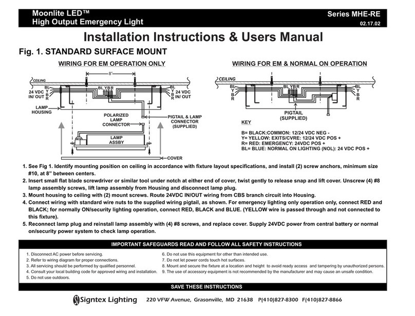
Tippkemper-Matrix Tippkemper LBS-235 SIL2 Series Installation instructions

ISO 9001:2008 / ATEX
Original Operating Manual:
Light Barriers series LBS/LBN/LBD-235-SHS/SDI/EHS(-OP)-SIL2
LBD-235-SHS/SDI/EHS-OP-SIL2 Housing M18 LBN-235-SHS/SDI/EHS-OP-SIL2
Page 1 of 2
•High penetration capacity in polluted areas.
•Optimal alignment by status visualization trough receiver optic
•Series LBD: ATEX and IECEx certified
•LBD: For use in Ex zones (0), 1, 2, (20), 21, 22
optical radiation can operate into Ex Zones 0, 20
•LBN: For use in Ex zones 2, 22
•Robust light barrier for industrial applications
0158
II 2(1)G
II 2(1)D II 3G Ex nA op is IIB T4 Gc
II 3D Ex tc op is IIIA T135°C Dc IP67
IECEx marking
Ex d [op is Ga] IIC T6 Gb
Ex tb [op is Da] IIIB T100°C Db IP67
IECEx BVS 14.0108X
Type designation emitter, standard LBS-235-SHS-SIL2 LBN-235-SHS-OP-SIL2 LBD-235-SHS-OP-SIL2
Type designation emitter, with disable input "DI" LBS-235-SDI-SIL2 LBN-235-SDI-OP-SIL2 LBD-235-SDI-OP-SIL2
Technical Data Type designation receiver LBS-235-EHS-SIL2 LBN-235-EHS-OP-SIL2 LBD-235-EHS-OP-SIL2
Type of Ex protection Gas, according to 2014/34/EU NONE II 3G Ex nA op is IIB T4 Gc II 2(1)G Ex d [op is Ga] IIC T6 Gb
Type of Ex protection Dust, according to 2014/34/EU NONE II 3D Ex tc op is IIIA II 2(1)D Ex tb [op is Da] IIIB
T135°C Dc IP67 T100°C Db IP67
For use in Ex zones NONE Zones 2, 22 Zones (0), 1, 2, (20), 21, 22
Performance Level (PL) PL C, according to EN 13849-1
Safety Integrity Level (SIL) SIL 2, according to EN 61508
Mean probability of a dangerous failure per hour PFHd 2.06 x 10⁻⁶, at 13849-1 (without PELV power supply)
Sensingrange 120m
Minimum detectable object size 12mm (avoid mirror effects)
Light source Infrared 870nm
Maximum radiant intensity NOTLIMITED <=5mWm2<=5mWm2
Maximumradiantpower NOTLIMITED < 35mW < 15mW
Optical angle of aperture (at a distance of 10m) Emitter: appr.30° / Receiver: appr.25°
Response time 5ms (Switch off time)
Power up delay time 300ms
Supply voltage 24 VDC +-10% (Power supply type PELV at EN 60204, item 6.4.2)
Absolute maximum supply voltage Um 30VDC
Current consumption, emitter 60mA
Current consumption, receiver 40mA
Maximum power dissipation Emitter: max. 1.6W / Receiver: 1.1W
Output PNP type, double guided, 100mA, short circuit protected
Permissible line resistance between device and load 10R
Pollution indication output "VA" PNP type, single guided, 100mA, short circuit protected
Emitter disable (test) input SDI, optional PNP compatible
Housing M18, brass Ms 58, nickel plated
Enclosure rating, in accordance with EN 60529 IP 65 IP 67 IP67
Ambient working temperature range Tamb 0°C up to +50°C
Storagetemperature range -20°C ... +70°C
Relative humidity 15% ... 90%, noncondensing
Vibration and shock resistance Vibration: 30g over 20Hz to 2kHz. Shock: 100g for 3ms
Pollution degree, in accordance with EN 60664-1:2007 4
Device designation, in accordance with EN 60947-5-2 LBS/LBN/LBD-235-***(-OP)-SIL2: T3A30BP1 / LBS/LBN-235-***(-OP)-SIL2--S099: T3A30BP2
Connection cable TPU insulation, AWM 20236, 2/3/4+PE x 0.5mm2, shielded,
leads numbering marked, oil resistant cable for trailing, length: 10m
Socket M12, only types LBS/LBN-235-(OP)-SIL2-S099 Socket , Lumberg RSFM 5, 5 pins
Accessories, all types, included - 4xnuts M18 (or optional 2x clamps, on request)
Accessories, only LBN-235-***-SIL2-S099, included - 1xSafety lock device, mount at the cable connection, for locking the connection.
- 1xWarning plate "Do not open/close when supply voltage connected",
self-sealing, for gluing on the cable connector.
- 1xProtection cap for the sensor socket.
Accessories, only LBN-235-***-SIL2-S099, not included - Single ended cordset, types RKTS 5-298/xx or RKWTH 5-298/xx, Lumberg
Options - LBS/LBN/LBD-235-***(-OP)-SIL2-S094: Lenses special luted
- LBS/LBN-235-***(-OP)-SIL2-S099: With socket M12, 5 pins
- LBS/LBN/LBD-235-SDI(-OP)-SIL2: Emitter with disable input DI
- Cable length: Up to 100m, on request
Light beam free
LED's shows yellow or green
Light beam interrupted
LED's shows red
LED display and
output function
Output function and wiring diagram (cable):
Receiver: Emitter:
1: =+24VDC 1: =+24VDC
2: = 0V 2: = 0V
3: = Output 3: =SDI,optional
4: = Pollution indication output "VA"
(Cable shields, connect to PE)
For connector types, see on page 2 of this operating
manual
Channel1
Channel2
+24VDC
Output
0V
+24VDC
Output
0V
PNP=ON
PNP=OFF Channel1
PNP=ON
PNP=OFF Channel2
Alignment and controlling by LED display
(Status visualization trough receiver optic and LED at the
rearside of the receiver)
LED red: Light beam interrupted / not aligned
LED yellow: Polluted lenses / badaligned
LED green: Light beam free / wellaligned
Function pollution indication output "VA" Output VA = 0V (LED's shows red) Output VA =24V if LED's shows yellow
Visible red light source
through the emitter
lens
EX related markings CE0158 Manufacturerwithaddress
TypesLBD: Exd [opisGa]IICT6Gb, Extb[opisDa]IIIBT100°CDbIP67
TypesLBN: II 3GExnAopisIIBT4Gc, II3DExtcopisIIIAT135°CDcIP67
TypesLBD: ATEXcertification No:BVS10ATEXE130XDEKRA
TypesLBD: IECExcertification IECEx BVS14.0108X
TypesLBN: ATEXdeclarationbymanufacturer inaccordancewiththeATEXdirective2014/34/EU
Tamb: 0°C < Tamb < +50°C Electricaldataaccordingtothetable"Technicaldata"
Dateofproduction: Numerals5to8oftheserialnumber(Year/calendarweek)
(Xdesignationofthecertificationnumber:Fibreopticsmustonlybeusedwithsensorswithcertificatedlimitedopticalpower)
LBD-235-OP-SIL2-IECEX_e2,2016-09-19/HB

Matrix Elektronik AG (Manufacturer) Tippkemper - Matrix GmbH
Kirchweg24 CH-542OEhrendingen MeegenerStr.43 D-51491 Overath
Tel.:+41 56 20400-20 Fax -29 Tel.:+49 2206 9566-0 Fax -19
Page 2 of 2
Safe equipotential Bonding
for Ex Devices:
to use light barriers with emitters with disable input. By using the disable input
DI, each emitter can be controlled in a short reaction time. If only one emitter
is activated in the same time, a mutual influence is precluded.
DI= 0V or not connected = emitter enabled
DI= High (24VDC) = emitter disabled
The Disable Input SDI must be activated for >= 15ms. The SDI input is PNP
compatible. The Emitter-Disable-Input DI can also be used for testing the
associated receiver. By a short-time shut-off of the emitter, the switching
off of the receiver output and with it the correct function of the receiver will
be checked.
Alignment of the Light Barrier:
The three color indication in the receiver optic allows an optimal alignment.
1. The emitter must be aligned this way, that the emitter lens is fully illuminated
(By watching from the receiver at the emitter).
2. The receiver should be moved, until the LED (from the receiver) shows
"green". Search the middle of the green range.
Maintenance:
No special maintenance is required. If the lenses becomes dirty, they should
be cleaned with a non-aggressive solvents. Equipment must only be repaired
by the manufacturer.
General safety instructions:
The operating manual provide the machine manufacturer’s or machine
operator’s technical personnel instructions on the safe mounting, configu-
ration, electrical installation, commissioning, and on the operation and
maintenance of the light barrier. Please read the operating instructions
carefully. Types: LBN-235-SHS/SDI-OP-SIL2-S099, LBN-235-EHS-OP-
SIL2-S099: : "WARNING - EXPLOSION HAZARD - WHEN IN HAZARD-
OUS LOCATIONS, TURN OFF POWER BEFORE REPLACING OR
WIRING MODULES. DO NOT DISCONNECT EQUIPMENT UNLESS
POWER HAS BEEN SWITCHED OFF OR THE AREA IS KNOWN
TO BE NONHAZARDOUS". The mounting of the sensor in dusty locations
without fixed cordset or protection cap results in a high ignition risk. In worst
case of breakdown, the output can change to any state! When installing
and operating with the sensor, it is necessary to take into consideration
the relevant international and other national regulations: EN 60079-14,
ATEX 118a, single directive 1999/92/EC. The sensors are conform to the
following standards:
IEC/EN 60079-0:2012 + A11:2013, IEC/EN 60079-1:2007, EN 60079-
15:2010, IEC/EN 60079-28:2007, IEC/EN 60079-31:2010, EN 13849-1:2008,
EN 61508-3:2010, EN 61326-3:2008, EN 60204-1:2005, EN 60529:2014,
EN 60950-1:2006; EN 61000-4-2 to EN 61000-4-6, EN 61000-6-1/-2, EN
61000-6-4, ATEX directive: 2014/34/EU, Machine directive: 2006/42/EC,
EMC directive: 2014/30/EU, RoHS directive: 2011/65/EU.
General Notes, disposal:
We reserve the right to modify our equipment. Our equipment is designed
such way, that it has the least possible adverse effect on the environment.
It neither emit or contain any damaging or siliconized substances and use
a minimum of energy and resources. No longer usable or irreparable units
must be disposed of in accordance with local waste disposal regulations.
EU-Declaration of conformity:
IECEx certification, types LBD: Ex d [op is Ga] IIC T6 Gb, Ex tb [op is Da]
IIIB T100°C Db IP67. Certification No. IECEx BVS 14.0108X.
http://iecex.iec.ch/iecex/iecexweb.nsf/0/FE79714C0BAEF6F5C1257D7E0044F6A9?opendocument
ATEX certification, types LBD: II 2(1)G Ex d [op is Ga] IIC T6 Gb, II 2(1)D
Ex tb [op is Da] IIIB T100°C Db IP67. Certification No. BVS 10 ATEX E 130
X, DEKRA EXAM GmbH, Zertifizierungsstelle, Carl-Beyling-Haus,
Dinendahlstrasse 9, D-44809 Bochum, Kennnummer: 0158.
ATEX certification, types LBN: II 3G Ex d op is IIB T4 Gc, II 3D Ex tc op
is IIIA T135°C Dc IP67. ATEX declaration by manufacturer in accordance
to the ATEX directive 2014/34/EU. ATEX certification of quality type
production of Ex devices in accordance to the directive 2014/34/EU, CE
0158. Certification No: BVS 12 ATEX ZQS / E118. The conformity of the
devices with the EC standards and directives and the EC-type examination
certificate and the observation of the Quality Safety System ISO
9001:2008 with the ATEX module "Production", declares:
Hans Bracher, Matrix Elektronik AG
Correct use
The barrier is a non-separating protective device at machinery directive
2006/42/EC. It must not be possible to start the machinery/system as
long as personnel are within the hazardous area. The double guided output
is only switched ON, when the light beam is not interrupted. The light
barriers are composed of an emitter and a receiver device only of the
same type. The types must not be mixed. The light barriers must only
be operated with post-switched emergency-stop devices or program-
mable safety devices. All relevant standards and directives for the
complete system or machinery, for performance level Plc, at EN ISO
13849-1, must be observed. The applicant is responsible to realize a
restart interlock at the machinery if requisite. This can be realized with
a with an external equipment. All warranty claims against Matrix Elektronik
AG are forfeited in the case of any other use, or alterations being made
to the system – even as part of their mounting or installation.
General prescriptions for all Ex devices:
It is necessary to take into consideration the valid international and national
rules and regulations (EN 60079-14). The maximum input voltage Um=30VDC
must not be exceeded. The local equipotential bonding have to be done.
The protective earth (PE) terminal is solid connected with the housing. The
cable have to be protected against damages. The cable with termination
fittings, or in cable tray systems and installed in a manner to avoid tensile
stress at the termination fittings. To connect cables inside hazardous
locations only use certificated Ex housings. All cable terminals must be
connected outside hazardous locations. Use only original manufactured
fibre optics and additional optical lenses, other additional optical lenses
are not allowed in hazardous locations.
Emitter: LBD-235-SHS/SDI-OP-SIL2, Receiver: LBD-235-EHS-OP-SIL2:
Applicable in Ex zones 1, 2, 21, 22. The limited optical radiation can operate
into hazardous locations 0 or 20 over certificated fibre optics or through
a viewing glass.
Emitter: LBN-235-SHS/SDI-OP-SIL2, Receiver: LBN-235-EHS-OP-SIL2:
Applicable only in Ex zones 2, 22.
Emitter: LBN-235-SHS/SDI-OP-SIL2-S099, Receiver: LBN-235-EHS-
OP-SIL2-S099: Applicable only in Ex zones 2, 22. WARNING! Do not
separate the connector when the supply voltage is connected to the cable.
When installing the sensor, the safety lock device must be fitted at the
cable connector. The additional adhesive warning label must be fixed
to the connector housing at the connection cable. Lumberg cordsets RKTS
5-298/xx (Straight type) or RKWTH 5-298/xx (Right angle type) are allowed
ONLY. It is necessary to take into consideration the mounting prescription
of the connector manufacturer. In dusty locations, the socket protection
cap must be fitted, when the connection cable is not connected.
General mounting prescriptions:
Do not exceed the maximum ratings. The electrical connections must be
exactly as shown in the connection diagram. The cable shield must be
connected short. The cable shield should be connected to the protection
earth, large-surfaced. Connection cables must not be installed parallel to
high voltage cables.
Function
If the light beam is not interrupted the output switches to ON (+24V). If
the light beam is interrupted the output switches to OFF. (The output is
built by 2 different PNP transistors, wired in series). The light barrier LBx-
235 works with two different light sources, visible red light and infrared. The
high density and the two different wavelengths gives a high penetration
capacity at a heavy polluted ambiance. The load (Relay or other loads) must
be connected at " - " (minus). Because the emitters has a very high optical
power, it's to avoid mirroring effects at the background, when not all
receivers are located at the same side.
Pollution indication output "VA"
The VA output will be activated by polluted lenses or a bad alignment. If
the lenses are polluted, the LED shows yellow and the VA output switches
to ON (+24V). This function gives the possibility to recognize pollutions
in a short time.
Arrangement of light barriers, types LB*-235-SDI(-OP)-SIL2 (op-
tional): If several light barriers are installed close to another, it is necessary
OperatingManual, EU-DeclarationofConformity:
The cable shield is to connect to PE in
a wide area.
12345678901234567890
12345678901234567890
12345678901234567890
12345678901234567890
12345678901234567890
12345678901234567890
12345678901234567890
1234567890123456789012345678901212345678901234567890123456789012123456
1234567890123456789012345678901212345678901234567890123456789012123456
1
1
1
1
1
1
1
1
1
1
1
1
1
123456
123456
12
12
12
12
12
123
1
The end of the cable must be connected
outside the hazardous locations.
Check the reliable, noncorrosive holding of
the protection earth connection.
LB*-235-SDI(-OP)-SIL2 (Emitter with optional disable input SDI)
Uin: SDI=+24V=disabled / 0V=enabled
Response time: <=5ms
Holdtime: >=15ms
+24V
DI
I**.-SDI Emitter
works
>=15ms SDI
=24V Emitterdisabled
output mustbeswitchedOFF SDI
=0V
5ms 5ms
Receiver: Emitter:
1/brown +24VDC +24VDC
2/white Pollutionindication output SDI (Disable input)
3/blue 0V 0V
4/black Output NC
5/grey PE PE
Wiring LBS/LBN-235-***(-OP)-SIL2-S099:
M12
LumbergRSF5,malesocket
51
4
3
2
LBD-235-OP-SIL2-IECEX_e2,2016-09-19/HB
DimensionsLBS/LBN-235-***(-OP)-SIL2-S099:
Same dimensions for
emitter and receiver SocketM12
Lumberg
RSF5
68
38
M18x1
108
D12
14
122
1234567890123456789012
1234567890123456789012
1234567890123456789012
1234567890123456789012
1234567890123456789012
1234567890123456789012
1234567890123456789012
1234567890123456789012
1234567890123456789012
123
1
2
3
1
2
3
1
2
3
1
2
3
123
LBN:Dust
protectioncapfor
thesocket
Receiver: Emitter:
+24VDC 1/brown 1/brown
0V 3/blue 3/blue
Output 4/black 4/black
VA-Output 2/white --
DI -- 2/white
PE 5/grey 5/grey
LEDatthe
receiver
1234567890123456789012345
1234567890123456789012345
1234567890123456789012345
1234567890123456789012345
1234567890123456789012345
1234567890123456789012345
1234567890123456789012345
1234567890123456789012345
1234567890123456789012345
1234567890123456789012345
Receiver: Emitter:
+24VDC 1 1
0V 2 2
Output 3 --
VA-Output 4 --
DI -- 3
PE yellow-green yellow-green
DimensionsLBS/LBN/LBD-235-***(-OP)-SIL2:
Same dimensions for
emitter and receiver
78
38 120
M18x1
D12
Dimensions: Tubus M18/90/8:
(Optional accessory for reduction the
directional angle) Aperture D8
D25
90
Screwing
M18x1 Material:
POM
88
This manual suits for next models
11
Table of contents
Popular Lighting Equipment manuals by other brands
Perel
Perel LBOXA5 user manual
LIGHTING Elements
LIGHTING Elements ATMOS user manual
Anslut
Anslut 422-363 operating instructions

Kaiser Fototechnik
Kaiser Fototechnik RB 550 AS operating instructions

DÖRR
DÖRR DSL-40 instruction manual

Francis Searchlights
Francis Searchlights A7179-L300RC User instruction & installation manual
