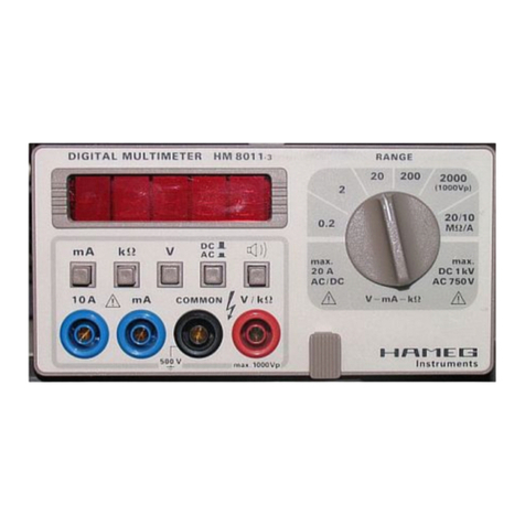
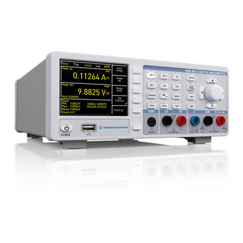
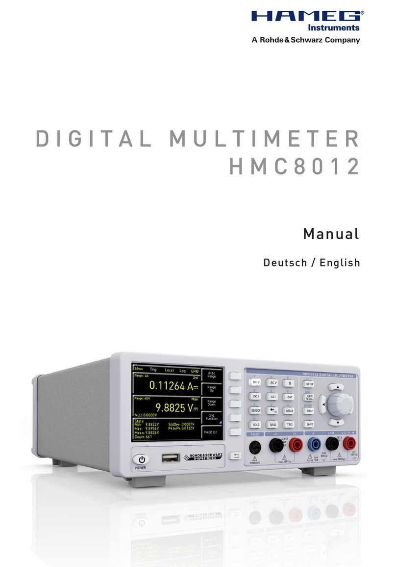
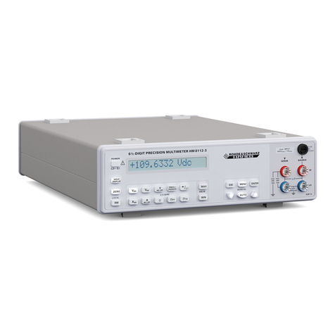
Hameg HM8112-3 User manual

6½-DIGIT
PRECISION-MULTIMETER
HM8112-3
Handbuch / Manual
Deutsch / English
99 Washington Street
Melrose, MA 02176
Fax 781-665-0780
TestEquipmentDepot.com

32 Subject to change without notice
General remarks regarding the CE marking
HAMEG measuring instruments comply with the EMI norms. Our tests for
conformity are based upon the relevant norms. Whenever different maximum
limits are optional HAMEG will select the most stringent ones. As regards
emissions class 1B limits for small business will be applied. As regards
susceptability the limits for industrial environments will be applied.
All connecting cables will influence emissions as well as susceptability
considerably. The cables used will differ substantially depending on the
application. During practical operation the following guidelines should be
absolutely observed in order to minimize EMI:
1. Data connections
Measuring instruments may only be connected to external associated
equipment (printers, computers etc.) by using well shielded cables. Unless
shorter lengths are prescribed a maximum length of 3 m must not be exceeded
for all data interconnections (input, output, signals, control). In case an
instrument interface would allow connecting several cables only one may be
connected.
In general, data connections should be made using double-shielded cables.
For IEEE bus connections the double-shielded HAMEG cables HZ72S and HZ72L
are suitable.
2. Signal connections
In general, all connections between a measuring instrument and the device
under test should be made as short as possible. Unless a shorter length is
prescribed a maximum length of 3 m must not be exceeded, also, such
connections must not leave the premises.
All signal connections must be shielded (e.g. coax such as RG58/U). With signal
generators double-shielded cables are mandatory. It is especially important
to establish good ground connections.
3. External influences
In the vicinity of strong magnetic or/and electric fields even a careful measuring
set-up may not be sufficient to guard against the intrusion of undesired signals.
This will not cause destruction or malfunction of HAMEG instruments, however,
small deviations from the guranteed specifications may occur under such
conditions.
HAMEG GmbH
Die HAMEG GmbH bescheinigt die Konformität für das Produkt
The HAMEG GmbH herewith declares conformity of the product
HAMEG GmbH déclare la conformite du produit
Bezeichnung / Product name / Designation:
Präzisions-Multimeter
Precision-Multimeter
Multimétre de précision
Typ / Type / Type: HM8112-3
mit / with / avec: –
Optionen / Options / Options: –
mit den folgenden Bestimmungen / with applicable regulations / avec les
directives suivantes
EMV Richtlinie 89/336/EWG ergänzt durch 91/263/EWG, 92/31/EWG
EMC Directive 89/336/EEC amended by 91/263/EWG, 92/31/EEC
Directive EMC 89/336/CEE amendée par 91/263/EWG, 92/31/CEE
Niederspannungsrichtlinie 73/23/EWG ergänzt durch 93/68/EWG
Low-Voltage Equipment Directive 73/23/EEC amended by 93/68/EEC
Directive des equipements basse tension 73/23/CEE amendée par 93/68/CEE
Angewendete harmonisierte Normen / Harmonized standards applied /
Normes harmonisées utilisées
Sicherheit / Safety / Sécurité
EN 61010-1:2001 (IEC 61010-1:2001)
Hersteller HAMEG GmbH KONFORMITÄTSERKLÄRUNG
Manufacturer Industriestraße 6 DECLARATION OF CONFORMITY
Fabricant D-63533 Mainhausen DECLARATION DE CONFORMITE
Überspannungskategorie / Overvoltage category / Catégorie de surtension: II
Verschmutzungsgrad / Degree of pollution / Degré de pollution: 2
Elektromagnetische Verträglichkeit / Electromagnetic compatibility /
Compatibilité électromagnétique
EN 61326-1/A1 Störaussendung / Radiation / Emission:
Tabelle / table / tableau 4; Klasse / Class / Classe B.
Störfestigkeit / Immunity / Imunitee: Tabelle / table / tableau A1.
EN 61000-3-2/A14 Oberschwingungsströme / Harmonic current emissions /
Émissions de courant harmonique:
Klasse / Class / Classe D.
EN 61000-3-3 Spannungsschwankungen u. Flicker / Voltage fluctuations and
flicker / Fluctuations de tension et du flicker.
Datum /Date /Date
01.12.2004
Unterschrift / Signature /Signatur
G. Hübenett
Produktmanager

33
Subject to change without notice
Content
Deutsch 3
English 32
Decleration of Conformity 32
General remarks regarding the CE marking 32
6½-Digit Precision-Multimeter HM8112-3 35
Specifications 35
Important hints 36
Symbols 36
Unpacking 36
Positioning 36
Transport 36
Storage 36
Safety instructions 36
CAT II 36
Proper operating conditions 37
Warranty and Repair 37
Maintenance 37
Protective Switch Off 37
Power supply 37
Line fuse 37
Power switch 37
Control-Elements 38
Concept of the HM8112-3 39
Reference 39
Integrated AD converters 39
Moving average 39
Measurement of alternating values 39
Introduction to the operation of the HM8112-3 39
Factory settings 39
Control elements and displays 40
Buttons for the various measurement functions 40
Continuity test 42
Max / Min values 42
Range selection 42
Menu structure 43
Menu prompting 44
Menu structure and function 45
Measurement inputs 46
Serial Interface 47
Data communication 47
Layout of commands 47
Listing of commands 48

34 Subject to change without notice
HM8112-3
6½-Digit Precision-Multimeter
HM8112-3
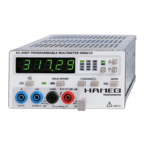
6½-digit LCD-display (1.200.000 points)
True rms measurements of AC+DC or AC
2-wire- / 4-wire measurements
Resolutions 100 nV, 100 pA, 100 µΩ, 0,01 °C / °F
Offset correction
Range selection automatically and manual
10 measurements per second
Measuring time 0,1 sec to 60 sec
Input impedance >1GΩ(0,1 V and 1VDC ranges)
RS-232 Interface (Option: USB, IEEE-488)
HZ42 19’’-rackmont-kit
Precise temperature
measurement with sensor
HZ887
˚C
˚F
RS-232

35
Subject to change without notice
Specifications
6½-Digit Precision-Multimeter HM8112-3
SPECIFICATIONS
Valid at 23 degrees °C after a 30 minute warm-up period
Included in delivery:
Multimeter HM8112-3, line cord, manual, HZ15 measuring cables
Accessories optional:
HZ887: Temperataure sensor (PT100; -50°C...+400°C )
HZ42:19" Rackmount-kit 2RU for frame height 75mm
DC Specifications
Ranges: 0.1 V; 1 V; 10 V; 100 V; 600 V
Input impedance:
0.1 V; 1.0 V >1 GΩ
10 V; 100 V; 600 V 10 MΩ
Accuracy: Values given are in ±(% of reading + % of full scale)
1 year; 23 ±2 °C Temperature coefficient
Range % rdg. + % f.s. 10...21 °C + 25...40 °C
0.1 V 0.005 + 0.0006 0.0008
1.0 V 0.003 + 0.0006 0.0008
10.0 V 0.003 + 0.0006 0.0008
100.0 V 0.003 + 0.0006 0.0008
600.0 V 0.004 + 0.0006 0.0008
Integration time: 0.1 sec 1 to 60 sec
Display range: 120,000 digit 1,200,000 digit
600 V range: 600,00 digit 600,000 digit
Resolution: 1 µV 100 nV
Zero point
Temperature coefficient: ≤0,3 µV/°C
Long term stability: ≤3 µV for 90 days
AC specifications
Ranges: 0.1 V; 1 V; 10 V; 100 V; 600 V
Measuring method: true rms DC or AC coupled
(except 0.1 V range)
Input impedance:
0.1 V: 1 GΩII <60 pF
1 V to 600 V: 10 MΩII <60 pF
Response time: 1.5 sec to within 0,1% of rdg.
Accuracy: For sine wave signals >5% of range.
Values given are in ±(% rdg. +% f.s.);23 ±2 °C for 1 year
Range 20 Hz – 1 kHz – 10 kHz – 50 kHz – 100 kHz –
1 kHz 10 kHz 50 kHz 100 kHz 300 kHz
0.1 V 0.10 +0.08 5+0.5 (5 kHz)
1.0 V 0.08 +0.08 0.15+0.08 0.3+0.1 0.8+0.15 7+0.15
10.0 V 0.08 +0.08 0.10+0.08 0.3+0.1 0.8+0.15 4+0.15
100.0 V 0.08 +0.08 0.10+0.08 0.3+0.1 0.8+0.15
600.0 V 0.08 +0.08 0.10+0.08
Temperature coefficient 10...21°C and 25...40°C; (%rdg. + %f.s.)
at 20 Hz - 10 kHz: 0.01 + 0.008
at 10 kHz - 100 kHz: 0.08 + 0.01
Crest factor: 7:1 (max. 5 x range)
Integration time: 0.1 sec 1 to 60 sec
Display range: 120,000 digit 1,200,000 digit
600 V range: 60,000 digit 600,000 digit
Resolution: 1 µV 100 nV
Overload protection:
(V-HI to V- LO) and to chassis:
Measurement ranges: all
all the time 850 Vpeak or 600 VDC
Maximum input voltage LOW against
chassis/safety earth: 250 Vrms at max. 60 Hz or 250 VDC
Current specifications
Ranges: 100 µA; 1 mA; 10 mA; 100 mA; 1 A
Integration time: 0.1 sec 1 to 60 sec
Display ranges: 120,000 digit 1,200,000 digit
1 A range: 100,000 digit 1,000,000 digit
Resolution: 1 nA 100 pA
Accuracy: DC 45 Hz–1 kHz 1 kHz–5 kHz
(1 year; 23 ±2 °C) 0.02+0.002 0.1+0.08 0.2+0.08
Temperature coefficient: 10...21 °C 25...40 °C
(% rdg. + % f.s.): 0.002+0.001 0.01+0.01
Voltage: <600 mV to 1,5 V
Response time: 1.5 sec to within 0.1% of rdg.
Crest factor: 7:1 (max. 5 x range)
Overload protection: Fuse FF 1 A 250 V
Resistance specifications
Ranges: 100Ω, 1kΩ, 10kΩ, 100kΩ, 1MΩ, 10MΩ
Integration time: 0.1 sec 1 to 60 sec
Display ranges: 120,000 digit 1,200,000 digit
Resolution: 1mΩ100 µΩ
Accuracy: Values given are in ±(% rdg. + % f.s.)
1 year; 23 ±2°C Temperature coefficient/°C
Range %rdg. + %f.s. 10...21 °C and 25...40 °C
100 Ω0.005 + 0.0015 0.0008
1 kΩ0.005 + 0.001 0.0008
10 kΩ0.005 + 0.001 0.0008
100 kΩ0.005 + 0.001 0.0008
1 MΩ0.05 + 0.002 0.002
10 MΩ0.5 + 0.02 0.01
Measuring current: Range Current
100 Ω, 1kΩ1 mA
10 kΩ100 µA
100 kΩ10 µA
1 MΩ1 µA
10 MΩ100 nA
max. measuring voltage: approx. 3 V
Overload protection: 250 Vpeak
Temperature measurement specifications
PT100 / PT1000 (EN60751) 2- or 4-wire measurements
Range: –200 °C to +800 °C
Resolution: 0.01 °C; measuring current 1mA
Accuracy: ±(0.05 °C + tolerance of sensor +0.08 K)
Temperature coefficient
(10...21 °C + 25...40°C: <0.0018 °C/°C
NiCr-Ni (K-Type)
Range: –270 °C to +1372 °C
Resolution: 0.1 °C
Accuracy: ±(0.7% rdg. +0.3 K)
Fe-CuNi (J-Type)
Range: –210 °C to +1200 °C
Resolution: 0.1 °C
Accuracy: ±(0.7% rdg. +0.3 K)
Frequency and period specifications
Range: 1 Hz to 100 kHz
Resolution: 0.00001 Hz to 1 Hz
Accuracy: 0.05% (rdg.)
Measuring time: 1 to 2 sec
RS-232 Interface
RS-232 standard: 9600 or 19200 Baud
Functions: Control / Data fetch
Inputs: Function, range, integration time, start
command
Outputs: Measurement results, function, range,
integration time (10 ms to 60 s)
Miscellaneous
Time to change range or function:
approx. 125 ms with DC voltage, DC current, resistance
approx. 1 sec with AC voltage, AC current
Memory: 30.000 readings / 128 kB
Protective class: I, EN 61010 (IEC 1010)
Power supply: 105–254 V; 50/60 Hz
Power consumption: approx. 8 W
Operating temperature: +10 °C....+40 °C
Storage temperature: –40 °C....+70 °C
Humidity: <75 %, no condensation
Size (W x H x D): 285 x 75 x 365 mm
Weight: approx. 3 kg
Optionen: USB- bzw. IEEE-Schnittstelle
Subject to change without notice
Test Equipment Depot - 800.517.8431 - 99 Washington Street Melrose, MA 02176
FAX 781.665.0780 - TestEquipmentDepot.com

36 Subject to change without notice
picture 3
picture 2
picture 1
Important hints
(1) (2) (3) (4) (5) (6)
Symbols
Symbol 1: Attention, please consult manual
Symbol 2: Danger! High voltage!
Symbol 3: Ground connection
Symbol 4: Important note
Symbol 5: Hints for application
Symbol 6: Stop! Possible instrument damage!
Unpacking
Please check for completeness of parts while unpacking. Also
check for any mechanical damage or loose parts. In case of
transport damage inform the supplier immediately and do not
operate the instrument.
Positioning
Two positions are possible: According to picture 1 the front
feet are used to lift the instrument so its front points slightly
upward. (Appr. 10 degrees)
If the feet are not used (picture 2) the instrument can be
combined with many other HAMEG instruments.
In case several instruments are stacked (picture 3) the feet
rest in the recesses of the instrument below so the instru-
ments can not be inadvertently moved. Please do not stack
more than 3 instruments. A higher stack will become unstable,
also heat dissipation may be impaired.
Transport
Please keep the carton in case the instrument may require
later shipment for repair. Losses and damages during
transport as a result of improper packaging are excluded from
warranty!
Storage
Dry indoor storage is required. After exposure to extreme
temperatures, wait 2 hr before turning the instrument on.
Safety instructions
The instrument conforms to VDE 0411/1 safety standards
applicable to measuring instruments and it left the factory in
proper condition according to this standard. Hence it conforms
also to the European standard EN 61010-1 resp. to the inter-
national standard IEC 61010-1. Please observe all warnings
in this manual in order to preserve safety and guarantee
operation without any danger to the operator. According to
safety class 1 requirements all parts of the housing and the
chassis are connected to the safety ground terminal of the
power connector. For safety reasons the instrument must only
be operated from 3 terminal power connectors or via isolation
transformers. In case of doubt the power connector should
be checked according to DIN VDE 0100/610.
Do not disconnect the safety ground either inside
or outside of the instrument!
– The line voltage of the instrument must correspond to the
line voltage used.
– Opening of the instrument is only allowed to qualified
personnel
– Prior to opening, the instrument must be disconnected
from the line voltage and all other inputs/outputs.
In any of the following cases the instrument must be taken
out of service and locked away from unauthorized use:
– Visible damage
– Damage to the power cord
– Damage to the fuse holder
– Loose parts
– No operation
– After long term storage in an inappropriate environment,
e.g. open air or high humidity.
– Excessive transport stress
CAT II
The following remarks concern only the safety of the user.
Other aspects e.g. the maximum input voltage etc. are covered
in the specifications section of this manual and are to be
observed as well.
Measurements in circuits which are indirectly connected with
the mains supply are possible with adequate converters (e.g.
clamp-on ammeters) which fulfil at least the requirements of
the safety class of the measurement. The measurement
category of the converter specified by the manufacturer must
be considered.
Measurement categories CAT
The measurement categories were created with respect to
the different kind of transients incurred in practice. Transients
STOP
STOP
STOP
Important hints
HINT

37
Subject to change without notice
are short, fast, and fast-rise changes of voltage or current,
and may be periodic or non-periodic. The amplitude of
transients increases with decreasing distance from their
source.
CAT IV: Measurements at the source of a low voltage supply,
e.g. at electricity meters.
CAT III: Measurements inside a building, e.g. at distribution
sites, power switches, permanently installed mains
outlets, permanently mounted motors etc.
CAT II: Measurements in circuits which are directly
connected with the low voltage supply, e.g. household
appliances, portable tools etc.
CAT I: Electronic instruments and circuits which contain
circuit breakers resp. fuses.
Proper operating conditions
Operation in the following environments: industry, business
and living quarters, small industry. The instruments are
intended for operation in dry, clean environments. They must
not be operated in the presence of excessive dust, humidity,
nor chemical vapours in case of danger of explosion.
The maximum permissible ambient temperature during
operation is +10 to +40 deg. C. In storage or during transport
the temperature limits are: –40 to +70 deg. C. In case of
exposure to low temperature or if condensation is suspected,
the instrument must be left to stabilize for at least 2 hrs prior
to operation.
In principle the instrument may be used in any position,
however sufficient ventilation must be ensured. Operation for
extended periods of time requires the horizontal or tilted
(handle) position.
Nominal specifications are valid after 30 minutes warm-up at
23 deg. C. Specifications without tolerances are typical values
taken of average production units.
Warranty and Repair
HAMEG instruments are subject to a strict quality control. All
instruments are burned in for 10 hrs prior to shipment. Alm-
ost all early failures are detected by intermittent operation.
After burn-in a thorough test of all functions and of quality is
run, all specifications and operating modes are checked.
In case of claims during the two years warranty period please
contact the dealer from whom you purchased your HAMEG
STOP
STOP
STOP
instrument. Customers from the Federal Republic of Germany
may directly contact HAMEG for warranty processing in order
to speed up the procedure.
The proceeding of repairs during the warranty period is subject
to our terms of warranty which are available on our web-site
(http://www.hameg.com). Even after expiry of the warranty
period please do not hesitate to contact our HAMEG customer
service for repairs and spare parts.
Return Material Authorization (RMA):
Before sending back your instrument to HAMEG do
apply for a RMA number either by fax or on the
Internet: http://www.hameg.de.
If you do not have suitable packaging for the in-
strument on hand please contact the HAMAG sales
department (Tel.: +49 (0) 6182/800 300, E-mail:
cardboard box.
Maintenance
The instrument does not require any maintenance. Dirt may
be removed by a soft moist cloth, if necessary adding a mild
detergent. (Water and 1 %.) Grease may be removed with
benzine (petrol ether). Displays and windows may only be
cleaned with a moist cloth.
Do not use alcohol, solvents or paste. Under no
circumstances should any fluid be allowed to get
into the instrument. If other cleaning fluids are
used damage to the lacquered or plastic surfaces
is possible.
Mains voltage
A main voltage of 115V and 230V can be chosen. Please check
whether the mains voltage used corresponds with the voltage
indicated by the mains voltage selector
30
on the rear panel.
If not, the voltage has to be changed.
Line fuse
The instrument has 2 internal line fuses: T 0.2 A. In case of a
blown fuse the instrument has to be sent in for repair. A change
of the line fuse by the customer is not permitted.
Power switch
Normally the power switch
28
on the rear
panel of the instrument should be stay in “ON“
position. If using the Standby-button on the
front panel, only the controls and the display
are turned off. The instrument itselfs stays
turned on as long as it is connected to the
supply voltage. This has the advantage that
the instrument is immediately functional after
turn-on. Also the reference voltage source will
remain energized, so any drift after turn-on will be eliminated,
also its long term drift will be substantially improved. To switch-
off the instrument completely, the power switch on the back panel
has to be operated.
If the instrument is left unattended for some time,
the power switch on the rear panel has to be
operated. (Because of safety reasons!)
Important hints
CAT IV CAT III CAT II
Premises
In-house
installation
Permanently installed
machinery, distribution sites,
power conductors, mains
outlets close to the CAT IV
installation
Mains outlets for
household appliances,
portable tools, PC,
refrigerator etc.
Overhead lines
Test Equipment Depot - 800.517.8431 - 99 Washington Street Melrose, MA 02176
FAX 781.665.0780 - TestEquipmentDepot.com
38 Subject to change without notice
Control elements
DISPLAY – 16 digit display
POWER – Stand by / ON
HOLD DISPLAY – storage of the displayed value
ZERO – 0-compensation of the measuring section
RM/LOCAL-pushbutton – Return to manual mode
VDC – Measurement of DC voltage
ADC – Measurement of DC current
VAC – Measurement of AC voltage with AC coupling
AAC – Measurement of AC current
VAC+DC – Measurement of AC voltage with DC coupling
11
Ω– Measurement of resistance, 2- and 4-wire
12
FREQ./PERIOD – Frequency and period measurement
with VAC
13
ϑPT - Measurement of temperature using a PT-sensor,
2- and 4-wire
14
- Diode test / Continuity test
15
ϑTH – Measurement of temperature using a
thermocouple, 2-wire
16
MAX – max. value during a test series
17
MIN – min. value during a test series
18
MENU – Call of the menu, acceptance of values entered
19
ESC – Leaving the menu without acceptance of the
values entered
20
– down: Switching to a higher range and scrolling
down the menu
21
AUTO – Activation/Deactivation of the auto range
function
22
ENTER – Special function: Parameter selection in the
logger menu
23
– up: Switching to a lower range and scrolling up the
menu
24
V SENSE – Input for measurements of voltage,
frequency, resistance, temperature
25
LO – Ground connection for inputs
24
and
26
26
A SOURCE – Input for current measurement
27
FUSE – 1 A / 250 V (FF) Measuring circuit fuse
Rear panelRear panel
Rear panel
28
Power receptacle with power switch
29
RS-232 Interface (Option: USB, IEEE-488)
30
Voltage selector (115 V / 230 V)
Control elements
12 27
3 4 5 6 7 8 9 10 11 12 13 14 15 16 17 19 20 18 21 22 23 24 25 26
29 28
30

39
Subject to change without notice
Introduction to the operation of the HM8112-3
Concept of the HM8112-3
Reference
The integrated AD converter has to be connected to a reference.
The characteristics of this reference determine the long term
stability of the instrument. The reference of HM8112-3 is therefore
a high precision reference device.
Integrated AD converters
Converters applying the multi slope method are used for AD
conversion.
Moving average
The value determined by the AD converter could be displayed
without prior computations, also the average calculated from
n – values could be shown. First of all 1 to n values will be
logged. Averaging over these values will be done, and sub-
sequently this average will be displayed. After 120 values the
next value n+1 will be quantified by the AD converter. The
primary measured value 1 will be abolished and a new average
will be calculated from the remaining values ( 2 to n) and from
the new value n+1. This has the advantage that peaks and
interferences will be smoothed.
Measurement of alternating values
Frequency, period
Frequency and period are both measured by a pulse-counting
circuit. Time base is 1 second. The first falling edge triggers
the measurement and starts the counter. For one second every
falling edge will trigger a counting pulse. After expiry of this
term the measurement circuit will wait for the next zero point.
Hence the signal’s period is measured. The time will be
measured until the next zero point occurs. The measurement
result determines the frequency of the signal and the period
will be calculated from the frequency. This combined
measurement of the number of zero points and of the period
of a signal allows the measurement of very small as well as
very high frequencies within a reasonable time. Applying of a
DC voltage results in a frequency displayed of 0 Hz.
As the period is calculated from the measured frequency
division by zero will be made. Therefore the instrument will
display „INF“ if the period of a DC voltage is measured („INF“
= infinity).
RMS rectifier
The AC voltage is measured by a high precision RMS rectifier
device. This device gauges a DC voltage proportional to the
applied AC voltage. This DC voltage is equivalent to the true
RMS value of the AC voltage.
Measurement of the crest factor
For crest factors exceeding 7 an AC voltage or current
measurement will be incorrect due to the true RMS converter.
Introduction to the operation of the HM8112-3
Especially before the first operation please pay attention to
the following points:
– The line voltage, indicated on the rear panel of the
instrument must correspond to the line voltage used.
– Operation is only allowed from 3 terminal connectors with
a safety ground connection or via isolation transformers
of class 2.
– No visible damage to the instrument.
– No damage to the line power cord.
– No loose parts in the instrument.
Factory settings
The following values are set by default:
– The measurement range is 10 VDC
– The sampling rate amounts to 100 ms
– The function „1:Filter“ is OFF
– The temperature is displayed in °C
– The selected temperature sensor is PT100
– The data logger is OFF
– The RS-232 interface is OFF
Test Equipment Depot - 800.517.8431 - 99 Washington Street Melrose, MA 02176
FAX 781.665.0780 - TestEquipmentDepot.com
40 Subject to change without notice
STOP
STOP
Control elements and display
Control elements and displays
Display
16 digit display for displaying measurement results, menu
selection and menu items.
POWER
Button for activating standby-function. The controls and the
display are turned off. The instrument itself stays turned on
as long as it is connected to the supply voltage. This has the
advantage that the instrument is immediately functional after
turn-on. Also the reference voltage source will remain
energized, so any drift after turn-on will be eliminated, also
its long term drift will be substantially improved.
To switch-off the instrument completely, the line switch on
the back panel has to be operated.
HOLD
“Freezing“ of the displayed measured value.
By pressing one of the function selection buttons to
15
or
MENU
18
the HOLD function is left.
ZERO
Zero for DC voltage, DC current, 4-wire-resistance and 2-wire-
resistance measurements. The ZERO function is not provided
for AC voltage and AC current measurements. Both cables
have to be shorted and the ZERO button has to be pressed.
This results in elimination of the resistances of the measure-
ment cables, resistances and thermal voltages at the junction
of different metals.
Compensation values remain, even after turn-off the instru-
ment. They have to be redetermined if necessary.
The ZERO button is deactivated in the measuring
functions ϑPT for PT sensors or ϑTH for
thermocouples.
Zero adjustment with temperature measurement
1. With regard to the type of temperature sensor one the
following measurement ranges must be chosen:
PT100 Ω2 wire / Ω4 wire 1 kΩrange
PT1000 Ω2 wire / Ω4 wire 10 kΩrange
Thermocouple VDC 100 mV range
Whether 2-wire- or 4-wire-measurement has to be
selected depends on the PT temperature sensor used.
2. Short the temperature sensor.
3. The ZERO button is to be pressed to compensate for
influences within the measurement circuit.
4. After compensation jump to the adequate temperature
measurement function by pressing ZERO
Some measurement instruments offer an „auto-
matic zero function“. This function regularly inter-
rupts the measurement and shorts the input. Then
a partial 0-adjustment is made.
The HM8112-3 has no AUTO ZERO function,
because the zero adjustment of the complete
measurement circuit is very important.
LOCAL
By sending a command via interface to the HM8112-3 the
instrument is set to the remote mode. Remote control is
switched off by pressing button LOCAL. The instrument
returns to manual mode and can be operated from the front
panel.
Buttons for the various measurement functions
If the measurement function is changed, the HM8112-3
assumes the sampling rate selected, unless a sampling rate
between 10 s and 60 s is chosen. Then changing the measuring
function will set the sampling rate automatically to 1 s.
The buttons offering more functions are illuminated. Naturally,
other measuring functions can be called up by pressing
unlighted buttons. The terminals are illuminated, too, and
indicate the terminals to be used with the corresponding
functions.
Voltage Measurement
VDC
Direct voltage measurement up to 600 V. No auto range
function in 100 mV and 1 V ranges.
12 27
3 4 5 6 7 8 9 10 11 12 13 14 15 16 17 19 20 18 21 22 23 24 25 26
VA
SENSE SOURCE
LO
HI
max.
250Vrms
max.
850
Vpk
max.
850
Vpk
Ω,
ϑ
FUSE
1A
F250V
CAT II
max. INPUT
600Vrms / 1Arms
+
–
Direct or
alternating voltage

41
Subject to change without notice
Frequency and period
12
FREQ./PERIOD
Switching between frequency and period measurement by
repeatedly pressing this button. At measurement of DC voltage
the display shows “0 Hz“ for frequency and “INF“ for period
measurement (INF = infinity). As the period is calculated from
the measured frequency it is a division by zero.
There is no auto range function for frequency and
period measurements. That means the range of
the VAC measurement is taken. Is necessary to
measure the alternating voltage in VAC first and
afterwards call up the FREQ./PERIOD function.
Temperature measurement
Switching between 2-wire and 4-wire measurement by
repeatedly pressing ϑPT-button
13
. This is indicated in the
display by „2w“ for 2-wire and by “4w“ for 4-wire measurement.
Additionally the terminals to be used are illuminated. For
compensation of the wiring resistance at 2-wire measure-
ments 100 mΩis stored by default. This value can be changed
via interface.
For exact measurements it is necessary to cali-
brate the measurement section with ZERO . This
calibration is done for PT sensors by resistance
measurement or for thermocouples by voltage
measurement but not by temperature measure-
ment (see ZERO ).
13
ϑPT with 4-wire-temperature measurement
Measuring method:
4 wire resistance measurement with linearisation
according to EN60751 for PT100 and PT1000.
Temperature sensor:
PT100, PT1000 resistance sensors
Display range: Display scale Resolution
Celsius: –200 °C to +800 °C 0.01 °C
Fahrenheit: –328 °F to +1472 °F 0.01 °F
Test current: PT100 1 mA
PT1000 100 µA
Control elements and display
VAC
Alternating voltage measurement up to 600 V, true RMS
without the DC component. In AC a capacitor is inserted. The
input impedance of the HM8112-3 is Ri= 10 MΩ.
VAC+DC
Alternating voltage measurement up to 600 V, true RMS with
DC component. Direct coupling of the circuit to the instrument
and using of the same high precision input divider like VDC.
The input impedance of the HM8112-3 is 10 GΩin 100 mV
range, 10 MΩin the other ranges.
Current
measurement
ADC
Direct current
measurement.
Auto range func-
tion up to and
including
the range 1 A
AAC+DC
Alternating current measurement, true RMS with DC com-
ponent. Auto range function over the entire range of 1 A.
Resistance measurement
Switching between 2 wire and 4 wire measurement by repeatly
pressing Ω-button
11
. This is shown in the display by „2w“ for
2 wire and by „4w“ for 4 wire measurement. Additionally the
terminals to be used are illuminated. For exact measurements
it is necessary to null any offsets by pressing ZERO .
11
Ω2-wire
resistance
measurement
For compensation
of the wiring resis-
tance with 2-wire
measurements
100 mΩis stored by
default. This value
can be changed via
the interface.
11
Ω4-wire
resistance
measurement
VA
SENSE SOURCE
LO
HI
max.
250Vrms
max.
850
Vpk
max.
850
Vpk
Ω,ϑ
FUSE
1A
F250V
CAT
II
max. INPUT
600V
rms
/ 1A
rms
+
–
Power
input
(Source)
+
–
Voltage
measurement
(Sense)
Resistance measurement
4-wire
VA
SENSE SOURCE
LO
HI
max.
250Vrms
max.
850
Vpk
max.
850
Vpk
Ω,
ϑ
FUSE
1A
F250V
CAT
II
max. INPUT
600Vrms / 1Arms
+
–
resistance
measurement
2-wire
STOP
STOP
VA
SENSE SOURCE
LO
HI
max.
250Vrms
max.
850
Vpk
max.
850
Vpk
Ω,
ϑ
FUSE
1A
F250V
CAT
II
max. INPUT
600Vrms / 1Arms
+
–
Direct or
alternating voltage
VA
SENSE SOURCE
LO
HI
max.
250Vrms
max.
850
Vpk
max.
850
Vpk
Ω,
ϑ
FUSE
1A
F250V
CAT
II
max. INPUT
600Vrms / 1Arms
+
Direct or alterDirect or alter
Direct or alter--
--
-
nating currentnating current
nating current
–
VA
SENSE SOURCE
LO
HI
max.
250Vrms
max.
850
Vpk
max.
850
Vpk
Ω,
ϑ
FUSE
1A
F250V
CAT
II
max. INPUT
600Vrms / 1Arms
+
–
Power
input
(Source)
+
–
4-wire-temperature measurement with PT100
Voltage
measurement
(Sense)
Test Equipment Depot - 800.517.8431 - 99 Washington Street Melrose, MA 02176
FAX 781.665.0780 - TestEquipmentDepot.com
42 Subject to change without notice
thermo-
couples
VA
SENSE SOURCE
LO
HI
max.
250Vrms
max.
850
Vpk
max.
850
Vpk
Ω,
ϑ
FUSE
1A
F250V
CAT II
max. INPUT
600Vrms / 1Arms
+
ContinuityContinuity
Continuity
test
–
STOP
STOP
Test voltage
(open circuit): 2.5 V
Measurement
period: 100 ms to 60 s
Delay: 100 ms (after change of function or range)
Calibration: with resistance measurement standard
PT100 1 kΩrange
PT1000 10 kΩrange
Linearisation: according to EN60751
13
ϑPT with 2-wire-temperature measurement
Limited accuracy of measured values for 2-wire-temperature
measurement with platinum temperature sensors PT100 or
PT1000.
Adjustment of measuring section with PT sensor
PT sensors have an output resistance which is mostly referred
in the data sheet. Often the data sheet is lost but the sensor is
still there. In HM8112-3 a value of 100 mΩis stored by default.
But some PT sensors have an integrated series resistance
(e.g. 10 mΩ). For an optimal adjusted measuring section the
exact output resistance must be known. This applies for 4-
wire measurement but especially for 2-wire measurements.
Via interface the default value stored ex factory can be aligned.
Values between 0 mΩand 100 mΩare possible.
Determination of the output resistance
The PT100 or PT1000 sensor has to be immersed in an ice
bath. At 0 °C the sensor has a resistance of 100 Ωand 1000 Ω
respectively. The resistance of the temperature sensor is taken
by a resistance measurement. The output resistance is the
difference between the measured value and the specified value.
15
ϑTH temperature measurement with thermocouples
Measuring method: Voltage measurement in 100 mV
range with linearisation according to
EN60584.
Display range: Thermocouples Range up to °C
J- Type (Fe-CuNi) –210 to +1200
K – Type (NiCr-Ni) –270 to +1372
Resolution: 0.1 °C / °F
Measurement period: 100 ms to 60 s
Delay: 100 ms (after change of function)
Display: Dimension °C or °F
Linearisation: according to EN60584
VA
SENSE SOURCE
LO
HI
max.
250Vrms
max.
850
Vpk
max.
850
Vpk
Ω,
ϑ
FUSE
1A
F250V
CAT II
max. INPUT
600Vrms / 1Arms
+
–
Power
input
(Source)
Continuity test
14
Continuity and diode test
Continuity test:
Activating of the loudspeaker for measured values between
0 Ω(short-circuit) and approx. 10 Ω.
Diode test: Test voltage approx. 2.5 V
Test current 1 mA constant
Max. forward voltage 1.2 V, otherwise
“Overflow VDC“ is displayed.
The test unit must be at zero potential during
continuity test.
Max / Min values
16
MAX /
17
MIN
The maximum or minimum measured value is displayed. As
this is possible in every measurement function, a system can
be controlled with respect to min/max values. There is no time
limitation, e.g. for activating this function for one year, the
minimum or maximum value measured during this year will
be displayed. This function is deactivated by pushing the keys
16
MAX or
17
MIN again. Changing the measurement function
will deactivate this function, too.
Range selection
Manual range selection
The range can be selected manually by pressing
20
and
23
.
20
Switch to a lower range. The auto range function will
be deactivated.
23
Switch to a higher range. The auto range function will
be deactivated.
If the applied measurement value exceeds the range, the
display will show „Overflow“.
21
AUTO
With button AUTO the auto range function can be activated.
This function is selectable for voltage, current and resistance
measurements.
As the autorange function is activated a higher range will be
selected after the measured value exceeds 90% of full scale.
The HM8112-3 will change to a lower range, if the value falls
below 10% of full scale. If the signal applied exceeds the
specified limits of the instrument in the autorange function,
the display shows “overflow“.
VA
SENSE SOURCE
LO
HI
max.
250Vrms
max.
850
Vpk
max.
850
Vpk
Ω,
ϑ
FUSE
1A
F250V
CAT II
max. INPUT
600Vrms / 1Arms
+
–
Control elements and display

43
Subject to change without notice
STOP
Menu structure
The autorange function is to be used with care. For
measurements on high impedance source and
measurement voltages in the range (90%) of full
scale 1 V, changing to a higher range is possible
with activated AUTO function. The HM8112-3 has
an input impedance of 10MΩin the 10 V range
instead of 1 GΩin the 1 V range. By loading a high
impedance source of several 100 MΩwith by input
impedance of 10 MΩthe measurement result will
be errouneous.
Menu structure
Menu prompting
From every measurement function the menu can be entered
by pressing MENU
18
. Within the menu, every button which
can be used is illuminated. The menu can be always left by
pressing ESC
19
without acceptance of entered values.
Call of the menu by MENU
18
.
Choice of menu item with
20
and
23
. The menu item is
opened with MENU
18
or branch to the next menu level.
Selection of parameters shown with
20
and
23
.
Acceptance of parameters changed with MENU
18
. If the menu
is left, the instrument will return to the last measurement
function.
19
ESC
Leaving the menu. Return to the last measuring function
without acceptance of the value entered.
20
Rotating menu prompting. Jump to the next menu item with
every key operation. On reaching the last menu item the display
continues with the first menu item.
23
Rotating menu prompting. Jump to the previous menu item
with every key operation. On reaching the first menu item the
display will roll over and continue with the last menu item.
22
ENTER
Use this button only in the logger menu „6:Logger.“ Switching
to the next buffered value by every key operation or acceptance
of an input.
Menu structure and function
The menu will be accessed by pressing MENU
18
. It branches
to the submenues described below.
0:Time
The time intervals between the measurements are adjustable
from 0.01 s to 60 s. That means, a reading is taken every 0.01 s
or only every 60 s.
The sampling rate can assume the following values:
10 ms (only via interface)
50 ms (only via interface)
100 ms (default setting after switch-on)
500 ms
1 s
10 s
60 s
That means, for example, that every 500 ms a measurement
is taken and the value is updated in the display. After switch-
on a value of 100 ms will be preset. Removal of the line voltage
will not save a selected value.
If the measurement function is changed, the HM8112-3
assumes the default sampling rate, unless a sampling rate
between 10 s and 60 s is chosen. Then changing the measuring
function sets the sampling rate automatically to 1 s.
Example: The sampling rate for VDC is set to 60 s. Then the
function ADC is selected. The instrument will reduce the
sampling rate automatically to 1 s. The new sampling rate
applies to all functions. If a sampling rate greater than 1 s is
needed, it has to be selected after every change of function.
A sampling rate of 60 s means:
The HM8112-3 integrates the input voltage and the
the reference voltage over a period of 60 s. After
expiry of this time the value calculated will be
displayed.
1:Filter
Selection of the number of values taken for averaging. In case
of selection of a number greater than 1, the selected number
will be taken for averaging. By calculating a new averaged
value, the first measured value will be discarded and the mean
value will be computed.
OFF (default setting after switch-on)
2
4
8
16
2:Temp
In this menu item the dimension for the temperature measure-
ment is selected.
° C Degrees Celsius
° F Degrees Fahrenheit
The dimensions selected last will be saved even if the mains
will be turned off.
3: Sensor
Here the temperature sensor used is selected.
After switch on of the HM8112-3 and selection of the menu item
“3:Sensor“, if a measurement function other than temperature
measurement was set, PT 100 as temperature sensor is selected
by default. If the thermocouple is chosen the HM8112-3 is in
measurement function
15
ϑTH.
Also the instrument will return to the measurement function
13
ϑPT after selection of the PT-sensor. The sensor type
selected last will be stored in the instrument even if the main
voltage is turned off.
– K–type: thermocouples NiCr-Ni (default setting after
switch-on)
– J–type: thermocouples Fe-CuNi
– PT1000: platinum resistance sensor with R0 = 1000 Ω
– PT100: platinum resistance sensor with R0 = 100 Ω(default
setting after switch-on)
Comp
For measurements with thermocouples a reference with a
known temperature must be defined. This reference tempera-
ture is provided to the HM8112-3. Therfore 3 methods are
possible:
HINT
Test Equipment Depot - 800.517.8431 - 99 Washington Street Melrose, MA 02176
FAX 781.665.0780 - TestEquipmentDepot.com
44 Subject to change without notice
Menu structure
default
default
default
Filter: Number of values for averaging
Selection of sampling rate
Call of the menu by: Selection of menu with:
Opening menu with:
Special function in the
Logger-Menu
see next page
Assuming parameter
and closing the menu:
Choose parameter:
¬
¬
MENU
MENU
¬
¬
MENU
¬¬ ¬
¬¬ ¬
0: Time
MENU MENU
MENU MENU
60s
10s
1s
500ms
100ms
1: Filter
last setting
Temperature: Selection of dimension
¬¬ ¬
MENU MENU
2: Temp
16
8
4
2
Off
default
Choice temperature sensor (PT100 / PT100, Fe - CuNi, NiCr - Ni)
¬¬ ¬
MENU MENU
3: Sensor K
J
PT1000
PT100
Comp
Fixing the reference for the thermocouple
¬¬ ¬
MENU MENU
Comp Comp Ext/Ice
Comp PT-Front
Comp 23°C/°F
default
General information
¬¬ ¬
MENU MENU
4: Info Version
Cal Date
Ser-Nr
Version 070404
CalL Date 170504
Ser-Nr 00007104
°F
°C
Selection Display
ENTER
Specification of an external ice bath, PT sensor or 23 °C as reference
¬¬
¬
MENU νPT MENU
Comp PT-Front
Using a PT sensor for reference point
measurement
Selection of
2- or 4-wire measurement
Acceptance of the displayed value
for reference
¬
Overview of menu structure – part 1

45
Subject to change without notice
default
Starting / Stopping the data logger, dumping the test series
¬¬ ¬
6: LOGGER
MENU MENU
Start
Stop
Dump
Dumping the test series
¬¬ ¬
Dump
MENU ENTER
Wert1 00001
00000
last setting
Interface RS-232: selecting the baud rate
¬¬ ¬
7: Com
MENU MENU
Rs19200
Rs9600
Off
Calibration
8: Cal
default
Math-Menu
¬¬ ¬
MENU MENU
5: Math Off
Lo Limit
Hi Limit
Offset
default
Scanner, choice of the channel
¬¬ ¬
MENU MENU
9: Mux empty
Chanal 1
. . . .
Chanal 8
¬
ENTER
Wert2 00002
¬
ENTER
Wertn 0000n
¬
ENTER
MENU ESC
Storage End
¬
by or leaving menu
¬
This area is protected by password
Overview of menu structure – part 2
Menu structure
1st: Comp Ext/Ice
An external temperature test point acts as a reference, e.g. an
ice bath or another reference thermocouple with a temperature
of 0° C, connected with the closed end to the measuring point,
and the reference put into the ice bath. The closed end of the
thermocouples can be connected with standard measurement
cables to the terminals of the HM8112-3.
2nd: Comp PT-Front
The temperature measured with a platinum sensor is the
reference for the measurement used with the thermocouples.
If several thermocouples will be attached to the HM8112-3 via
a scanner, the use of the ice bath would be necessary for each
thermocouple. To overcome this, the ambient temperature or
even a source with a constant temperature is taken as the
reference (e.g. ice bath, heated reference). If “PT-Front“ is
seleced by pressing MENU
18
the function ϑPT will be
activated. Now 2- or 4-wire measurement can be chosen. Then
the reference temperature is measured with a platinum sensor
and assumed by confirmation with button MENU
18
. In case
of 2-wire measurement the PT-sensor can stay connected to
the thermocouple. For 4-wire measurement it has to be dis-
connected and replaced by the connection of the thermocouple.
3rd: Comp 23° C/ °F
A temperature of 23° C is specified as reference. For measure-
ments of high temperatures the resulting measurement error
can be neglected, unless the open end of the thermocouple is
on the level of the ambient temperature. The ambient tem-
perature should be about 23° C.
4:Info
In this menu item all instrument information is available:
Version: Display of revision number of the software
Ser-Nr: Display of the intrument’s serial number
Cal date: Display of the date of the last calibration.
Test Equipment Depot - 800.517.8431 - 99 Washington Street Melrose, MA 02176
FAX 781.665.0780 - TestEquipmentDepot.com
46 Subject to change without notice
STOP
STOP
27
24 25 26
5: Mathematics
Analysis of different characteristics of the measured values
OFF The menu item 5:Math is off.
Lo Limit Lower limit.
If the measured value is smaller than the LoLo
LoLo
Lo
LimitLimit
LimitLimit
Limit value
an acoustic warning sounds and “Lo
limit“ is displayed.
Hi Limit Higher limit.
If the measured value is greater than Hi LimitHi Limit
Hi LimitHi Limit
Hi Limit
value
an acoustic warning occurs and „Hi limit“
is displayed.
Offset An offset value can be set for all measurement
functions to
15
a) Apply the offset value to the terminals.
b) Choose menu item 5:Math.
c) Select submenu „Offset“ by pressing
23
.
d) Open the submenu with MENU
18
, the
offset value applied will be displayed.
e) Accept the offset by pressing MENU
18
.
f) Return to measurement function, the display
shows 0,00…., , the dimension and „Os“.
g) Now you can connect the value to be
measured. It is compared the calibrated value
and the deviation is displayed.
In order to delete the stored offset:
a) Choose menu item 5:Math.
b) Select submenu „Off“ by pressing
23
.
c) Accept by pressing MENU
18
, return to
measurement function, the measured value is
displayed without offset.
or
d) select another measurement function.
The offset value will not be stored when the
measurement function is changed.
6:Logger
Analysis of different characteristics of the measured values
Start The test series is started. According to the
selected sampling rate in „0:Time“ every xx
second a reading is taken and stored.
Stop The test series is stopped.
Dump The test series is shown on the display. Each
time button ENTER
22
is pressed the next value
of the stored test series is displayed.
7:COM
In this menu the baud rate can be chosen. Either 9600 baud or
19200 baud are available. The remaining interface parameters
cannot be changed.
Interface parameters (adjustable)
Rs Off The interface is switched off
Rs19200 19,200 baud
Rs9600 9,600 baud
Interface parameters (not selectable)
N no parity bit
8 8 data bits
1 1 stop bit
Xon-Xoff Xon-Xoff
Every transmission of a character takes 1 ms.
Selecting a sampling rate of 0.01 sec requires a
baud rate of 19 200.
Measurement inputs
8:Cal
This menu is saved by password. In order to guarantee exact
measurements the HM8112-3 is calibrated. Calibration may
only be done with adequate precision reference sources. For
this purpose the password can be orderd at HAMEG GmbH
(Tel.: 06182-800-500 or via E-Mail: service@hameg. de).
Attention:
After receiving the password any warranty claims of HAMEG
GmbH concerning the compliance with the technical specifi-
cations of the instrument become void.
9:Mux
For the future implementation of a scanner/test point switch.
Measurement inputs
For connection measurement signals the HM8112-3 features
4 safety connectors on the front panel. Depending on the
measurement function chosen, the active terminals will be
illuminated.
The terminals on the front panel are safety connec-
tors and the regulations have to be observed.
If connecting dangerous voltages to the input
terminals
24
and
26
all relevant safety regulations
are to be observed.
DC voltage must be floating!
AC voltage must be floating by use of a safety
isolating transformer.
Attention!
Voltages exceeding one of the following values are
regarded potentially dangerous or even lethal:
1st 30 Vrms
2nd 42.4 Vpeak
3rd 60 VDC
Connecting higher voltages than those is only
allowed to skilled personnel who are familiar with
the dangers incurred. The relevant safety
regulations are to be strictly observed!

47
Subject to change without notice
STOP
STOP
STOP
Serial interface
24
V/SENSE (4mm safety sockets)
Connection of measuring cables for:
– voltage measurement
– frequency measurement
– 4 wire resistance measurement (SENSE)
– continuity test
– temperature measurement by a thermocouple
– 4 wire temperature measurement by a P–temperature
sensor (SENSE)
The maximum voltage between HI and LO case
(ground) must not exceed 850 V-peak or 600 VDC.
The maximum voltage between LO and case
(ground) may not exceed 250 Vrms!
26
A/SOURCE (4mm safety socket)
Connection of measuring cables for:
– current measurement, max. 1 ampere
– 2 wire resistance measurement
– 4 wire resistance measurement (SOURCE)
– 4 wire temperature measurement by a PT – temperature
sensor (SOURCE)
– continuity test up to 10 Ω
The maximum current may amount to 1 Aeff!
25
LOW (4mm safety connectors)
Ground connection for inputs
24
and
26
. Both connectors are
high-impedance DC-isolated.
27
Fuse in the current measuring circuit
The shunt is fuse-protected. The fuse (FF) is located in a fuse
holder. The measuring circuit is designed for a maximum
allowable measurement current of 1 ampere.
Replacement of the fuse is only allowed, after the
instrument was disconnected from the mains!
A repair of a defective fuse or bypassing the fuse is
very dangerous and absolutely prohibited!
Replacement of the measuring circuit fuse
The measuring circuit fuse
27
is accessible from the front
panel. A replacement of the fuse is only allowed, if no voltage
is applied to the measuring connectors! Therefore all terminals
V/SENSE
24
, ground
25
and A/SOURCE
26
should be
disconnected. The cover of the fuse holder has to be turned
ccw with a screw driver having a suitable blade. As the cover
can be turned it has to be pushed by the srew driver into the
fuse holder. The cover with the fuse can then be easily taken
out. Replace the defective fuse by a new fuse of the same type
having the same trip current. A repair of a damaged fuse or
the use of other means for bypassing the fuse is very dangerous
and absolutely prohibited! Damages incurred will void the
warranty.
28
Power receptacle with power switch
Power receptacle for connecting the line cord with according
to DIN49457.
29
Serial Interface RS-232
The RS-232 interface is on the rear panel of the HM8112-3
(9-pin D-sub socket). The bidirectional interface of HM8112-3
can receive data (commands) from an external device (PC) or
send data (measurement values and parameters).
30
Voltage selctor
Choice of mains voltage (115 V / 230 V).
Serial Interface
The serial interface is electrically isolated from the measuring
circuit (Options: USB, IEEE-488).
The instrument is programmable by a PC
Functions and ranges can be selected and measurement
values stored in the instrument can be read out.
The HM8112-3 is connected to another instrument
by a 1:1 interface cable. It is recommended to use
a 9 to 25 pin standard adapter if a PC with a 25 pin
COM port isconnected.
Interface parameters
Settings: No parity bit, 8 data bits, one stop bit, Xon-Xoff
Baudrate: The communication is carried out with 9600
baud or 19200 baud.
HINT
29 28
30
Test Equipment Depot - 800.517.8431 - 99 Washington Street Melrose, MA 02176
FAX 781.665.0780 - TestEquipmentDepot.com
48 Subject to change without notice
Listing of commands
Data communication
Layout of commands
A command consists of 5 ASCII characters:
1. Character: 0
2. Character: Command category (0, 1, 2 or E)
3. Character: Function between 0 and F
4. Character: Parameter between 0 and F
5. Character: Terminator, either CR or LF
– all commands end with CR or LF
– the character set includes figures 0 – 9, characters A – F
and CR, LF
– the characters can be entered as upper case or lower case
letters
– Figures 2, 3 and 4 received after 0 are interpreted as a
control command. After a command has been transmitted
a delay of at least 35 ms must be observed, then the next
command can be sent.
– A transmission of invalid commands is answered with
2D0LF2D0LF
2D0LF2D0LF
2D0LF in case of wrong length of the command or void
command category, with 2D1LF2D1LF
2D1LF2D1LF
2D1LF for group 1, with 2D2LF2D2LF
2D2LF2D2LF
2D2LF
for group 2 and with 2DELF2DELF
2DELF2DELF
2DELF for group E. This helps
debugging the controller program. The error message is
transmitted immediately after occurrence.
Notes concerning some commands:
0000…0004 Measurement of DC voltage, ranges 100 mV to
600 V
0010…0014 True RMS with DC
0016…0019 True RMS without DC
02C3…02C5 This message is sent after a change of function
or range
02F0…02F3 Request of the instrument’s data
By pressing button „LOCAL“ the instrument
returns to manual mode.
HINT

49
Subject to change without notice
Listing of commands
The commands have to be transmitted as characters or a numeric string in ASCII format. Characters may be lower or upper key. Each command must use CR (Chr (13) corresponds 0x0D)
or LF (Chr (10) corresponds 0x0A) as its end.
1st 2nd 3rd Character 4th Character PARAMETER 5th
Character Type Function 0 123456789Character
0VDC
100mV 1V 10V 100V 600V - - - - No Change
1VAC 100mV-DC 1V-DC 10V-DC 100V-DC 600V-DC - 1V-AC 10V-AC 100V-AC 600V-AC
2IDC 0,1mA 1mA 10mA 100mA 1A - - - - No Change
3IAC 0,1mA 1mA 10mA 100mA 1A - - - - No Change
4OHM 2WIRE 100Ohm 1kOhm 10kOhm 100kOhm 1MOhm 10MOhm - - - No Change
05OHM 4WIRE 100Ohm 1kOhm 10kOhm 100kOhm 1MOhm 10MOhm - - - No Change
8FREQ/PERIOD VAC - FREQ PERIOD - - - - - - -
BDiode test ---------NoChange
CContinuity ------10Ohm---
DSensor RTD 2WIRE - - - Pt100 - Pt1000 - - - -
ESensor RTD 4WIRE - - - Pt100 - Pt1000 - - - -
FSensor TH -JK-------
0AUTO-RANGE OFFON------UPDOWN
1MEAS-Time - 10ms 50ms 100ms 500ms 1s 10s 60s UP DOWN
3Filter CONT 2 4 8 16 - - - - -
04Math OFF OFFSET HIGH LIMIT LOW LIMIT - - - MAX MIN - CR
6TRIGGER AUTO SINGLE --------or
17Measurement mode -ZEROCAL-------LF
8Temp ----°C°F----
9Logger STOP START DUMP SINGLE DUMP CLEAR REC. END REC. EMPTY STOR FULL - -
ABUFFER OFF ON DUMP SINGLE DUMP CLEAR AUTO CLEAR BUF. EMPTY - - -
BRECORD NR. -1234568-->F
CSensor Comp EXT/ICE 23°C FRONT - - - - - - -
FTEST - RAM - - RAM GOOD RAM FAIL - - - -
2Com RS232 OFF - - 9600 19200 - - - - -
2CMESSAGE - - STATE DUMP STATE OFF AUTO STATE CONT STATE - - - -
DERROR LENGTH GROUP 1 GROUP 2 - - - - - --> E GROUP E
FInfo - data read REVISION LAST CAL SER NUM LEAD RES - - - - - -
E3Cal - Reference valu
e
XXXXXXX Password
FDATA WRITE - - - LEAD RES - - - - - -
Survey of the commands for HM8112-3
Listing of commands
Test Equipment Depot - 800.517.8431 - 99 Washington Street Melrose, MA 02176
FAX 781.665.0780 - TestEquipmentDepot.com
Other manuals for HM8112-3
2
Table of contents
Other Hameg Multimeter manuals

Hameg
Hameg HM 8040-2 User manual

Hameg
Hameg HM8112-3 User manual

Hameg
Hameg HM 8012 User manual

Hameg
Hameg HM 8012 User manual

Hameg
Hameg HM8112-3 User manual

Hameg
Hameg HMC8012 Operating and maintenance manual

Hameg
Hameg HM8112-3S User manual

Hameg
Hameg HM 8012 User manual

Hameg
Hameg HM8011-3 User manual

Hameg
Hameg HMC8012 User manual
Popular Multimeter manuals by other brands

Extech Instruments
Extech Instruments MiniTec Series user manual

Gossen MetraWatt
Gossen MetraWatt METRACLIP 86 user manual

Gossen MetraWatt
Gossen MetraWatt METRALINE EXM25 operating instructions

Klein Tools
Klein Tools ET100 instruction manual

PCE Americas
PCE Americas PCE-LCT 1 user manual

Unitest
Unitest BEHA 9004 instruction manual