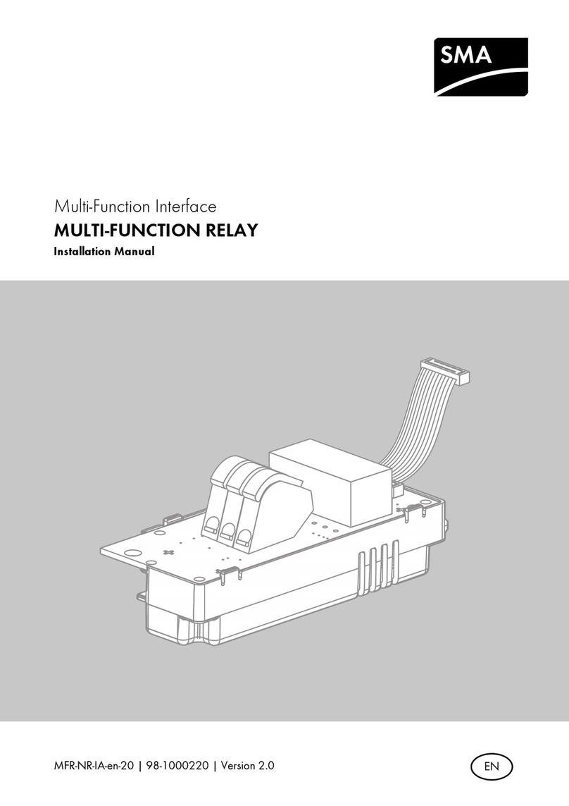
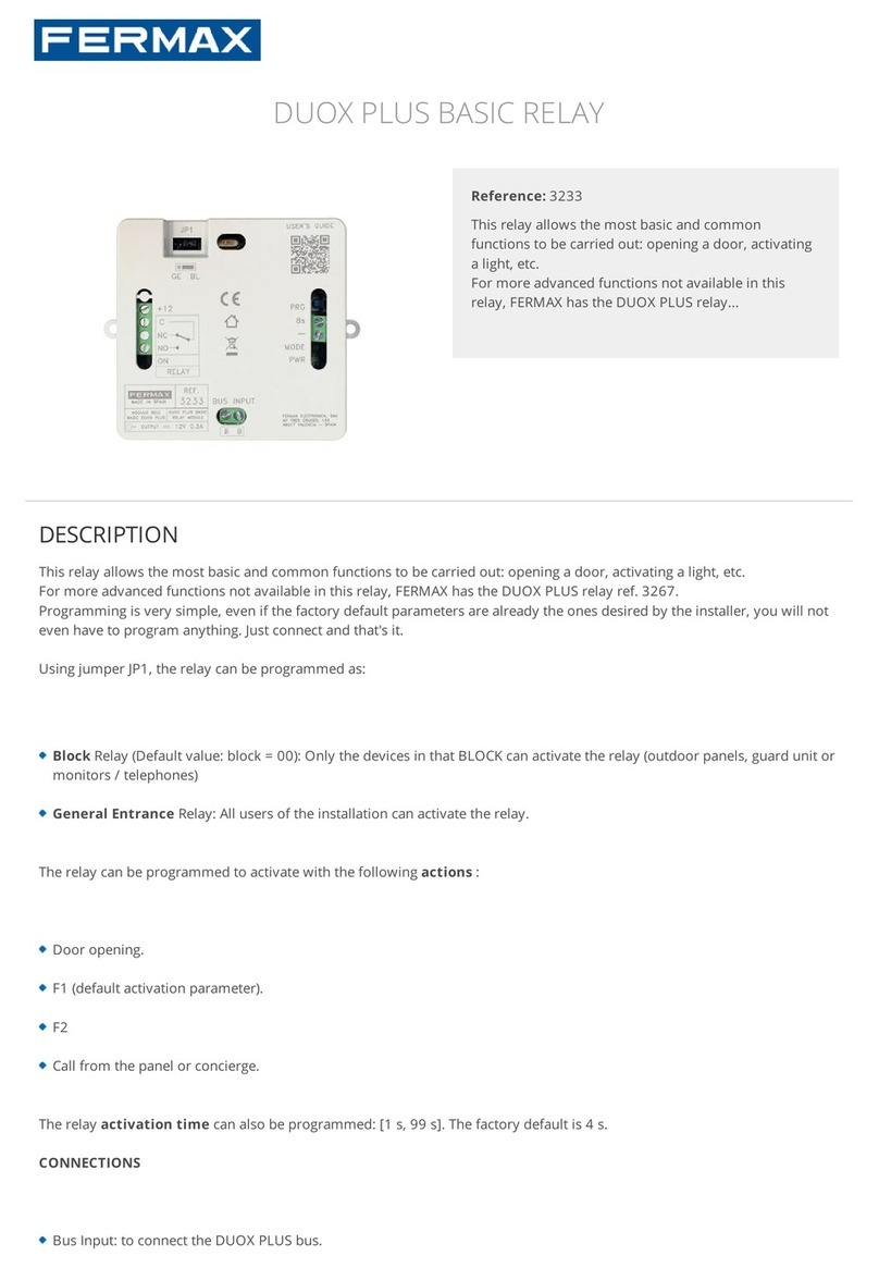
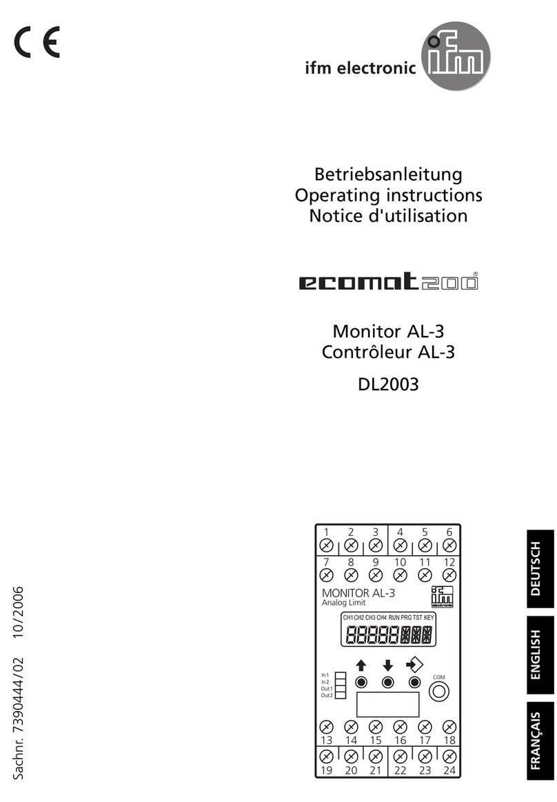
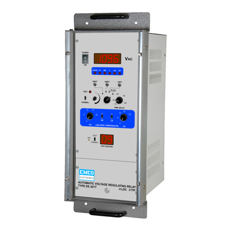
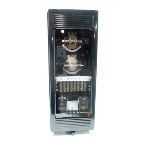
TIS ACM-2R-2Z User manual

This product is a Wi-Fi enabled universal dimmer
module with remote control capability over the
internet via the TIS App. It features dry input(s)
particularly designed to be coupled with any push-
button wall switch for smart lights control.
PRODUCT INFORMATION
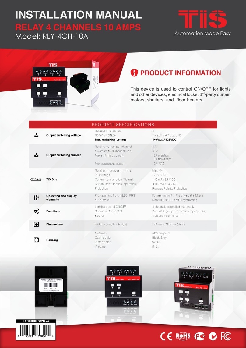
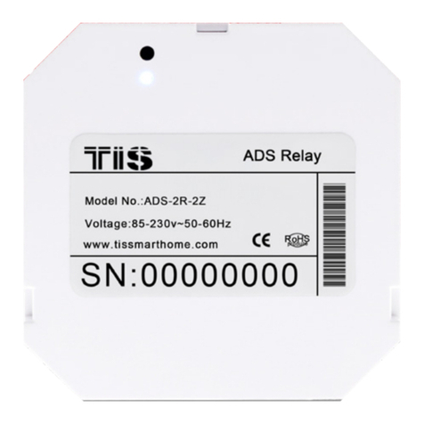
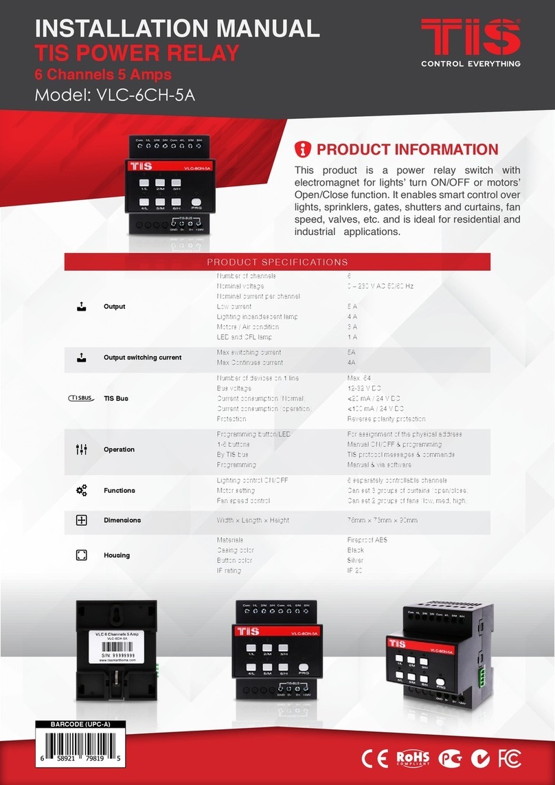
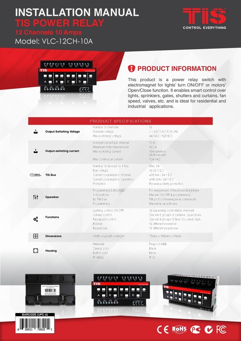
WIRELESS ACM RELAY
INSTALLATION MANUAL
Model: ACM-2R-2Z
WI-FI CONTROLLER WITH 2 DRY INPUTS
BARCODE (UPC-A)
6 58921 79631 3
PRODUCT SPECIFICATIONS
Power supply
Input voltage 110-230 VAC 50/60 Hz
Output power 3W / 12V
Protection Internal protection fuse
Current consumption 10-20 mA / 12 V DC
Output
Number of relays 2
Nominal voltage 110 / 230 V AC 50/60 Hz
Nominal current per channel 3 A / 230 VAC
Output switching current
Max Switching current 3A/230 VAC resistive
2A/230 VAC florescent
Max Continues current 3A/230 VAC
Max Switching voltage 230VAC / 30VDC
Output service life Mechanical endurance > 10,000,000 OPS
Output switching times
Operating time 8mS (at nomi. Volt)
Releasing time 5mS (at nomi. Volt)
Max. operating frequency 25 cycle/min
TIS AIR WIFI signal 2.4 GHz
Protocol standard 802.11 b/g/n
Operation
Digital inputs 2 dry inputs for lights control
TIS AIR TIS protocol messages & commands
PRG button with LED For programming
Upgrading Over WIFI connection
Dimensions (Width × Length × Height) 20mm × 49mm × 49mm
Housing
Materials Fireproof PC
Internal parts color White
IP rating IP 50

INSTALLATION MANUAL
Model: ACM-2R-2Z
WIRELESS ACM RELAY
2
www.tiscontrol.com
TIS CONTROL LIMITED
Wanchai, Hong Kong
TIS CONTROL PTY LIMITED
SA , AUSTRALIA
Copyright © 2022 TIS, All Rights Reserved
TIS Logo is registered trademark of TIS CONTROL.
All of the specification are subject to change without notice.
Mounting Location
Install in a dry, indoor area with a suitable
temperature and humidity range.
Electrical Wires
The recommended wire size for light
channels is 2.5mm, for the Line, Neutral,
and Load cables. The installer should
consider the total current consumption
when selecting the wires.
Warranty
There is a two-year warranty provided
by law. The hologram warranty seal and
product serial number are available on
each device.
Read Instructions
We recommend that you read this
Instruction Manual before installation.
Safety instructions
Electrical equipment should only be
installed and tted by electrically skilled
persons.
Failure to observe the instructions may
cause damage to the device and other
hazards.
These instructions are an integral part of
the product and must remain with the end
customer.
Programming
This device can be tested and
programmed manually. Advanced
programming requires knowledge of
the TIS Device Search software and
instruction in the TIS advanced training
courses.
Simple Installation
it ts on most junction box sizes or can be
located anywhere.

INSTALLATION MANUAL
Model: ACM-2R-2Z
WIRELESS ACM RELAY
3
www.tiscontrol.com
TIS CONTROL LIMITED
Wanchai, Hong Kong
TIS CONTROL PTY LIMITED
SA , AUSTRALIA
Copyright © 2022 TIS, All Rights Reserved
TIS Logo is registered trademark of TIS CONTROL.
All of the specification are subject to change without notice.
INSTALLATION STEPS
2Remove the switch cover. Unscrew and
pull the wall switch out. Take the wires
out of the load and line.
3Find a total of 5 wires.
1Turn off the power at the main circuit
breaker to turn off voltage supply to the
switch.
Neutral
Live
Switch 1
Switch 2
Earth
WARNING! HIGH VOLTAGE
Circuit Breaker
OFF

INSTALLATION MANUAL
Model: ACM-2R-2Z
WIRELESS ACM RELAY
4
www.tiscontrol.com
TIS CONTROL LIMITED
Wanchai, Hong Kong
TIS CONTROL PTY LIMITED
SA , AUSTRALIA
Copyright © 2022 TIS, All Rights Reserved
TIS Logo is registered trademark of TIS CONTROL.
All of the specification are subject to change without notice.
INSTALLATION STEPS
4Turn on the power at the main power
breaker, and carefully identify the live
wire using a voltage tester and nd the
neutral wire.
5Turn off the power at the main power
breaker again to turn off the voltage
supply to the switch.
6
▸
Attach the neutral and the live wires to
the N & L terminals, respectively.
▸
For the 110/220V Loads, you need to
connect the L and C terminals.
▸
For the dry contact control, keep the C
terminal disconnected.
Circuit Breaker
ON
Circuit Breaker
OFF
110 ~ 220 Volt
1.5 mm Electric Cable
1.5 mm Electric Cable
2.5 mm Electric Cable
Connect To L
Open
Close
0.OFF
1.ON
Connect To L
MCB
Connect To N
Connect To N
COM
Z2Z1 C
www.tissmarthome.com
AIRCOUPLER MODULE
ModelNo: ACM-2R-2Z
Voltage:110-230V 50/60HZ
TISControl Hong Kong
L N C S1 S2
Connect To N
Connect To N
1.5 mm Electric Cable
2.5 mm Electric Cable
low voltage cable
low voltage cable
1.5 mm Electric Cable
Connect To L
O-OFF
I-ON
MCB
C
Z2 Z1
www.tissmarthome.com
AIR COUPLER MODULE
Model No: ACM-2R-2Z
Voltage: 110-230V 50/60HZ
TIS Control Hong Kong
L N C S1 S2
Traditional Switch
▸
Attach the switch1 & 2 wires to the S1 &
S2 terminals, respectively.
▸
Connect the 2 Dry inputs wires to the
wall switch.

INSTALLATION MANUAL
Model: ACM-2R-2Z
WIRELESS ACM RELAY
5
www.tiscontrol.com
TIS CONTROL LIMITED
Wanchai, Hong Kong
TIS CONTROL PTY LIMITED
SA , AUSTRALIA
Copyright © 2022 TIS, All Rights Reserved
TIS Logo is registered trademark of TIS CONTROL.
All of the specification are subject to change without notice.
INSTALLATION STEPS
7Turn on the breaker. The module should
turn on accordingly.
8
9
Start the programming and test the
device performance using the app.
(See p. 6 for server linking and p. 8 for
conguration steps).
If the module works accurately, then
insert the ACM Module into the junction
box, and x it to the wall.
Circuit Breaker
ON

INSTALLATION MANUAL
Model: ACM-2R-2Z
WIRELESS ACM RELAY
6
www.tiscontrol.com
TIS CONTROL LIMITED
Wanchai, Hong Kong
TIS CONTROL PTY LIMITED
SA , AUSTRALIA
Copyright © 2022 TIS, All Rights Reserved
TIS Logo is registered trademark of TIS CONTROL.
All of the specification are subject to change without notice.
SERVER LINKING
In order for a project to be fully linked to the TIS server, server conguration must be
enabled in just 1 product within that project.
If you have already done that with any other panel, just ignore these steps and proceed to
conguration steps.
To do the server linking, complete the following steps:
2On the module, press and hold the PRG
button for 6 seconds. The PRG LED will
start blinking.
1In the TIS App, go to Settings Connect
Server, and follow the steps by entering
your SSID password.
21
6”

INSTALLATION MANUAL
Model: ACM-2R-2Z
WIRELESS ACM RELAY
7
www.tiscontrol.com
TIS CONTROL LIMITED
Wanchai, Hong Kong
TIS CONTROL PTY LIMITED
SA , AUSTRALIA
Copyright © 2022 TIS, All Rights Reserved
TIS Logo is registered trademark of TIS CONTROL.
All of the specification are subject to change without notice.
SERVER LINKING
4Select your server option and 4-digit
password. Then, press Save.
3On the TIS app, press Search and wait
for a few seconds. The panel will link to
your Wi-Fi, and the PRG LED will turn
blue.
21

INSTALLATION MANUAL
Model: ACM-2R-2Z
WIRELESS ACM RELAY
8
www.tiscontrol.com
TIS CONTROL LIMITED
Wanchai, Hong Kong
TIS CONTROL PTY LIMITED
SA , AUSTRALIA
Copyright © 2022 TIS, All Rights Reserved
TIS Logo is registered trademark of TIS CONTROL.
All of the specification are subject to change without notice.
21
1In the TIS App, go to the Settings AIR
Device Conguration, and follow the
steps by entering your SSID password.
2On the module, press and hold the PRG
button for 6 seconds. The PRG LED will
start blinking.
CONFIGURATION STEPS
3On the TIS app, press Search and wait
for a few seconds. The panel will link to
your Wi-Fi, and the PRG LED will turn
blue.
6”

INSTALLATION MANUAL
Model: ACM-2R-2Z
WIRELESS ACM RELAY
9
www.tiscontrol.com
TIS CONTROL LIMITED
Wanchai, Hong Kong
TIS CONTROL PTY LIMITED
SA , AUSTRALIA
Copyright © 2022 TIS, All Rights Reserved
TIS Logo is registered trademark of TIS CONTROL.
All of the specification are subject to change without notice.
2
2
1
1
5 Select the room; then, select channel
names and icons.
4 Select the Relay type (Lights, Curtain).
6 Go to the congured room’s page and
start controlling.
CONFIGURATION STEPS
ACM-2R-2Z ACM-2R-2Z

INSTALLATION MANUAL
Model: ACM-2R-2Z
WIRELESS ACM RELAY
10
www.tiscontrol.com
TIS CONTROL LIMITED
Wanchai, Hong Kong
TIS CONTROL PTY LIMITED
SA , AUSTRALIA
Copyright © 2022 TIS, All Rights Reserved
TIS Logo is registered trademark of TIS CONTROL.
All of the specification are subject to change without notice.
PAIRING (MANUAL PROGRAMMING)
4 The same procedure must be followed to program other relay channels. The only exception is that
you must press the PRG button six times for channels 2. The following table displays method info
in detail.
To pair the TIS ACM module with any TIS wall panel buttons, do the following:
2 Go to any other wall panel and short
press on any lighting button.
CHANDELIER
00-00-00 IN 22
SPOTLIGHT
CEILING
WALL LIGHT
ROPE LIGHT
FLUORESCENT
1Short press on the PRG button ve times
in a row until the PRG LED starts to blink
every 2 seconds.
×5
3 Test by pressing on the wall panel’s
ON/OFF button. The module relay
should respond by turning ON and OFF
accordingly.
CHANDELIER
00-00-00 IN 22
SPOTLIGHT
CEILING
WALL LIGHT
ROPE LIGHT
FLUORESCENT

INSTALLATION MANUAL
Model: ACM-2R-2Z
WIRELESS ACM RELAY
11
www.tiscontrol.com
TIS CONTROL LIMITED
Wanchai, Hong Kong
TIS CONTROL PTY LIMITED
SA , AUSTRALIA
Copyright © 2022 TIS, All Rights Reserved
TIS Logo is registered trademark of TIS CONTROL.
All of the specification are subject to change without notice.
USER OPERATION
Use your mobile app or smart wall
switches to control lights ON/OFF.
Notice: Wall switches need to be
congured with this module’s dry inputs
beforehand.
TROUBLESHOOTING
PRG button blinks purple
color rapidly
Reason: The panel address conicts with another
device in the TIS network. You need to press and
hold the PRG button for 6 seconds so that the
module can get a new address.
Device can’t link to Wi-Fi
router Reason: The device is not connected to Wi-Fi.
Other wall panels can’t pair
with the device
Reason 1: The device is too far from the Wi-Fi
router.
Reason 2: The SSID or password is not correct.
Reason 3: Some setting in the WIFI router is
preventing new devices from being added.
Other wall panels can’t
control the device channels
Reason 1: Other panel connections are not linked
to the same Wi-Fi network.
Reason 2: The manual programming function is
disabled in the device (default is enabled).
Table of contents
Other TIS Relay manuals
