SMA Solar Technology MFR01-10 User manual

MFR-NR-IA-en-20 | 98-1000220 | Version 2.0
EN
Multi-Function Interface
MULTI-FUNCTION RELAY
Installation Manual


SMA Solar Technology AG Table of Contents
Installation Manual MFR-NR-IA-en-20 3
Table of Contents
1 Information on this Document. . . . . . . . . . . . . . . . . . . . . . . . . . . 5
2 Safety . . . . . . . . . . . . . . . . . . . . . . . . . . . . . . . . . . . . . . . . . . . . . . 7
2.1 Intended Use . . . . . . . . . . . . . . . . . . . . . . . . . . . . . . . . . . . . . . . . . . . . 7
2.2 Qualification of Skilled Persons . . . . . . . . . . . . . . . . . . . . . . . . . . . . . . 8
2.3 Safety Precautions . . . . . . . . . . . . . . . . . . . . . . . . . . . . . . . . . . . . . . . . 8
3 Scope of Delivery . . . . . . . . . . . . . . . . . . . . . . . . . . . . . . . . . . . . . 9
4 Product Description . . . . . . . . . . . . . . . . . . . . . . . . . . . . . . . . . . 10
5 Electrical Connection . . . . . . . . . . . . . . . . . . . . . . . . . . . . . . . . . 12
5.1 Safety during Electrical Connection. . . . . . . . . . . . . . . . . . . . . . . . . . 12
5.2 Mounting Position and Cable Routing . . . . . . . . . . . . . . . . . . . . . . . . 12
5.3 Installing the Multi-Function Relay in the Inverter . . . . . . . . . . . . . . . . 13
5.4 Multi-Function Relay Connection . . . . . . . . . . . . . . . . . . . . . . . . . . . . 15
5.4.1 Connection Options for the Multi-Function Relay. . . . . . . . . . . . . . . 15
5.4.2 Connection to the Multi-Function Relay . . . . . . . . . . . . . . . . . . . . . . 19
6 Setting the Operating Mode of the Multi-function Relay . . . . 22
7 Technical Data . . . . . . . . . . . . . . . . . . . . . . . . . . . . . . . . . . . . . . 23
8 Contact . . . . . . . . . . . . . . . . . . . . . . . . . . . . . . . . . . . . . . . . . . . . 24

Table of Contents SMA Solar Technology AG
4 MFR-NR-IA-en-20 Installation Manual
SMA Solar Technology AG 1 Information on this Document
Installation Manual MFR-NR-IA-en-20 5
1 Information on this Document
Validity
This document is valid for device type "MFR01-10".
Target Group
This document is for skilled persons. Only qualified personnel with the appropriate skills are allowed
to perform the tasks described in this manual (see Section2.2 "Qualification of Skilled Persons",
page8).
Additional Information
Links to additional information can be found at www.SMA-Solar.com:
Symbols
Document title Document type
Measured Values and Parameters Technical description
Temperature Derating Technical information
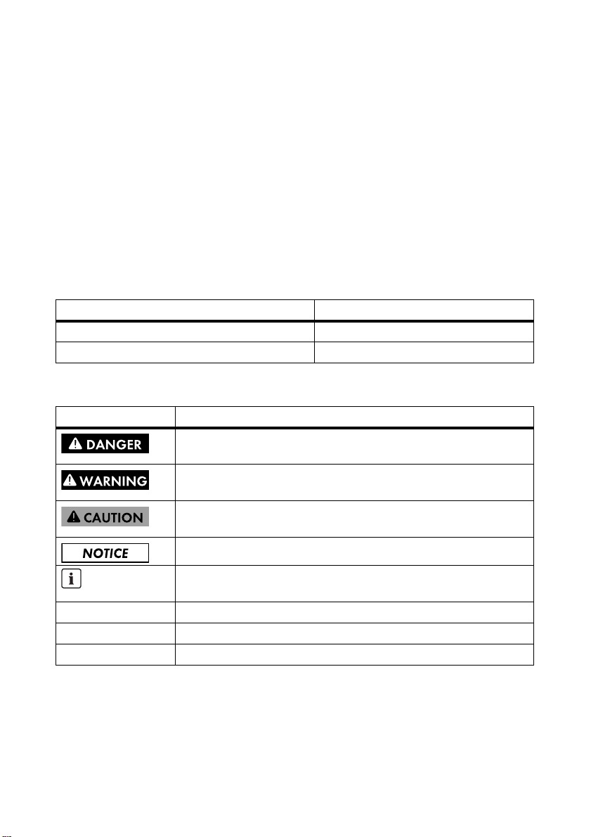
Symbol Explanation
Indicates a hazardous situation which, if not avoided, will result in death
or serious injury
Indicates a hazardous situation which, if not avoided, could result in death
or serious injury
Indicates a hazardous situation which, if not avoided, could result in minor
or moderate injury
Indicates a situation which, if not avoided, could result in property damage
Information that is important for a specific topic or goal, but is not
safety-relevant
☐ Indicates an essential requirement for achieving a specific goal
☑ Desired result
✖ A problem that might occur

1 Information on this Document SMA Solar Technology AG
6 MFR-NR-IA-en-20 Installation Manual
Typography
Nomenclature
Display of Parameters
Depending on the type of communication, RS485, Bluetooth or Speedwire, the parameters are
displayed differently in the communication products. This document contains both display types.
Typography Usage Example
bold • Parameter
• Elements to be selected
• Elements to be entered
• Select the parameter
Operating mode of
multifunction relay or
Mlt.OpMode and set the
desired operating mode .
Full designation Designation in this document
Sunny Boy, Windy Boy, Sunny Tripower Inverter
Operating parameter Parameter
Example: Display of the operating mode parameter of the multi-function relay
• With communication via RS485: parameter Mlt.OpMode
• With communication via Bluetooth or Speedwire: parameter Operating mode of
multi-function relay

SMA Solar Technology AG 2 Safety
Installation Manual MFR-NR-IA-en-20 7
2Safety
2.1 Intended Use
You can use the multi-function relay for various purposes:
The multi-function relay is suitable for use in the following SMA inverters:
• SB 3000TL-21, SB 3600TL-21, SB 4000TL-21, SB 5000TL-21
• WB 3000TL-21, WB 3600TL-21, WB 4000TL-21, WB 5000TL-21
• SB 2500TLST-21, SB 3000TLST-21
• STP 8000TL-10, STP 10000TL-10, STP 12000TL-10, STP 15000TL-10, STP 17000TL-10
• STP 15000TLHE-10, STP 20000TLHE-10, STP 15000TLEE-10, STP 20000TLEE-10
Use the multi-function relay only for one of the indicated purposes. Any other use may result in
personal injury or property damage.
For safety reasons, it is not permitted to modify the product or install components that are not explicitly
recommended or distributed by SMA Solar Technology AG for this product.
The enclosed documentation is part of this product.
• Read and adhere to the documentation.
• Keep the documentation in a convenient place for future reference.
Application
(operating mode)
Description
Fault indication/FltInd The multi-function relay controls a display device which, depending on
the type of connection, either reports an error or the undisturbed
operation of the inverter.
Self-consumption/
SelfCsmp
The multi-function relay switches loads on or off, depending on the
power supply status of the plant.
Control via communication/
ComCtl
The multi-function relay switches the loads on and off via a
communication product.
Battery bank/BatCha The multi-function relay controls battery charging, depending on the
power supply situation of the plant.
Fan control/FanCtl The multi-function relay controls an external fan depending on the
temperature of the inverter.
Switching status grid relay/
GriSwCpy
The local network operator may require that a signal is transmitted as
soon as the inverter connects to the electricity grid.
The multi-function relay simulates the switching status of the grid relay
and trips a signal to the network operator.

2 Safety SMA Solar Technology AG
8 MFR-NR-IA-en-20 Installation Manual
2.2 Qualification of Skilled Persons
The work described in this document must be performed by skilled persons only. Skilled persons must
have the following qualifications:
• Knowledge of how an inverter works and is operated
• Training in how to deal with the dangers and risks associated with installing and using electrical
devices and plants
• Training in the installation and commissioning of electrical devices and plants
• Knowledge of the applicable standards and directives
• Knowledge of and adherence to this document and all safety precautions
2.3 Safety Precautions
Electric Shock
High voltages which may cause electric shocks are present in the conductive parts of the inverter.
• Prior to performing any work on the inverter, always disconnect the inverter as described in the
corresponding installation manual from any voltage sources on the AC and DC sides
(see inverter installation manual).
Burn Hazards
Some parts of the enclosure may get hot during operation.
• Do not touch any parts other than the lower enclosure lid of the inverter during operation.
Electrostatic Discharge
Touching electronic components can cause damage to or destroy the inverter through electrostatic
discharge.
• Earth yourself before touching any components.
• Avoid contact with components or plug contacts inside the inverter.

SMA Solar Technology AG 3 Scope of Delivery
Installation Manual MFR-NR-IA-en-20 9
3Scope of Delivery
Check the scope of delivery for completeness and any externally visible damage. Contact your
specialist dealer if the scope of delivery is incomplete or damaged.
Figure1: Components included in scope of delivery
Item Quantity Description
A 1 Multi-function relay*
B 1 M20x1.5 cable gland*
* If the multi-function relay has already been installed at the factory, this component is not included.
C 1 Installation manual
D 1 M4x8 cheese-head screw*
E1Washer M4*

4 Product Description SMA Solar Technology AG
10 MFR-NR-IA-en-20 Installation Manual
4Product Description
You can use the multi-function relay for various purposes:
The multi-function relay can be retrofitted, or installed in the inverter at the factory if specified in the
order.
Application (operating
mode)
Description
Fault indication/FltInd The multi-function relay controls a display device which, depending on
the type of connection, either reports an error or the undisturbed
operation of the inverter.
Self-consumption/
SelfCsmp
The multi-function relay switches loads on or off, depending on the
power supply status of the plant.
Control via communication/
ComCtl
The multi-function relay switches the loads on and off via a
communication product.
Battery bank/BatCha The multi-function relay controls battery charging, depending on the
power supply situation of the plant.
Fan control/FanCtl The multi-function relay controls an external fan depending on the
temperature of the inverter.
If the temperature of the inverter is 5°C higher than a specific
threshold set in the inverter, the fan starts automatically. If the
temperature of the inverter is 10°C lower than the threshold, the fan
stops automatically.
Switching status grid relay/
GriSwCpy
The multi-function relay switches simultaneously with the grid relay of
the inverter.

SMA Solar Technology AG 4 Product Description
Installation Manual MFR-NR-IA-en-20 11
Figure2: Design of the multi-function relay
There are different connection procedures depending on how you intend to use the multi-function
relay (see Section5.4.1 "Connection Options for the Multi-Function Relay", page15).
The operating mode of the multi-function relay has been set by default to Fault indication/FltInd.
If you have chosen another operating mode, you need to change the operating mode of the
multi-function relay via a communication product after commissioning the inverter and possibly adjust
other settings as well (see Section6 "Setting the Operating Mode of the Multi-Function Relay",
page22).
Symbol on Product
Item Description
A Connecting terminal plate for the connection to the multi-function relay
B Ribbon cable for the connection in the inverter
CHole for attaching the multi-function relay in the inverter
Symbol Description Explanation
Danger to life due to high
voltages
The inverter operates at high voltages.
All work on the inverter and on the
multi-function relay must be carried out by
skilled persons only.
5 Electrical Connection SMA Solar Technology AG
12 MFR-NR-IA-en-20 Installation Manual
5 Electrical Connection
5.1 Safety during Electrical Connection
Electric Shock
High voltages which may cause electric shocks are present in the conductive parts of the inverter.
• Prior to performing any work on the inverter, always disconnect the inverter as described in the
corresponding installation manual from any voltage sources on the AC and DC sides
(see inverter installation manual).
Electrostatic Discharge
Touching electronic components can cause damage to or destroy the inverter through electrostatic
discharge.
• Earth yourself before touching any components.
• Avoid contact with components or plug contacts inside the inverter.
5.2 Mounting Position and Cable Routing
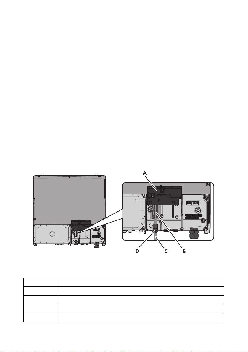
Mounting Position and Cable Routing in the Sunny Tripower
Figure3: Installation area and cable route in the Sunny Tripower with the lower enclosure lid open and the
display flipped up
Item Description
AInverter display
B Installation location of the multi-function relay
C Cable route for the connection to the multi-function relay
D M20x1.5 cable gland
SMA Solar Technology AG 5 Electrical Connection
Installation Manual MFR-NR-IA-en-20 13
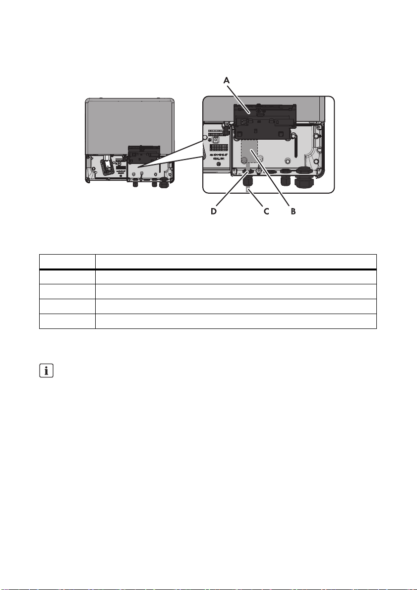
Mounting Position and Cable Routing in the Sunny Boy/Windy Boy
Figure4: Installation area and cable route in the Sunny Boy/Windy Boy with the lower enclosure lid open and
the display flipped up
5.3 Installing the Multi-Function Relay in the Inverter
1. Disconnect the inverter from voltage sources on the AC and DC sides and open the lower
enclosure lid (see the inverter installation manual).
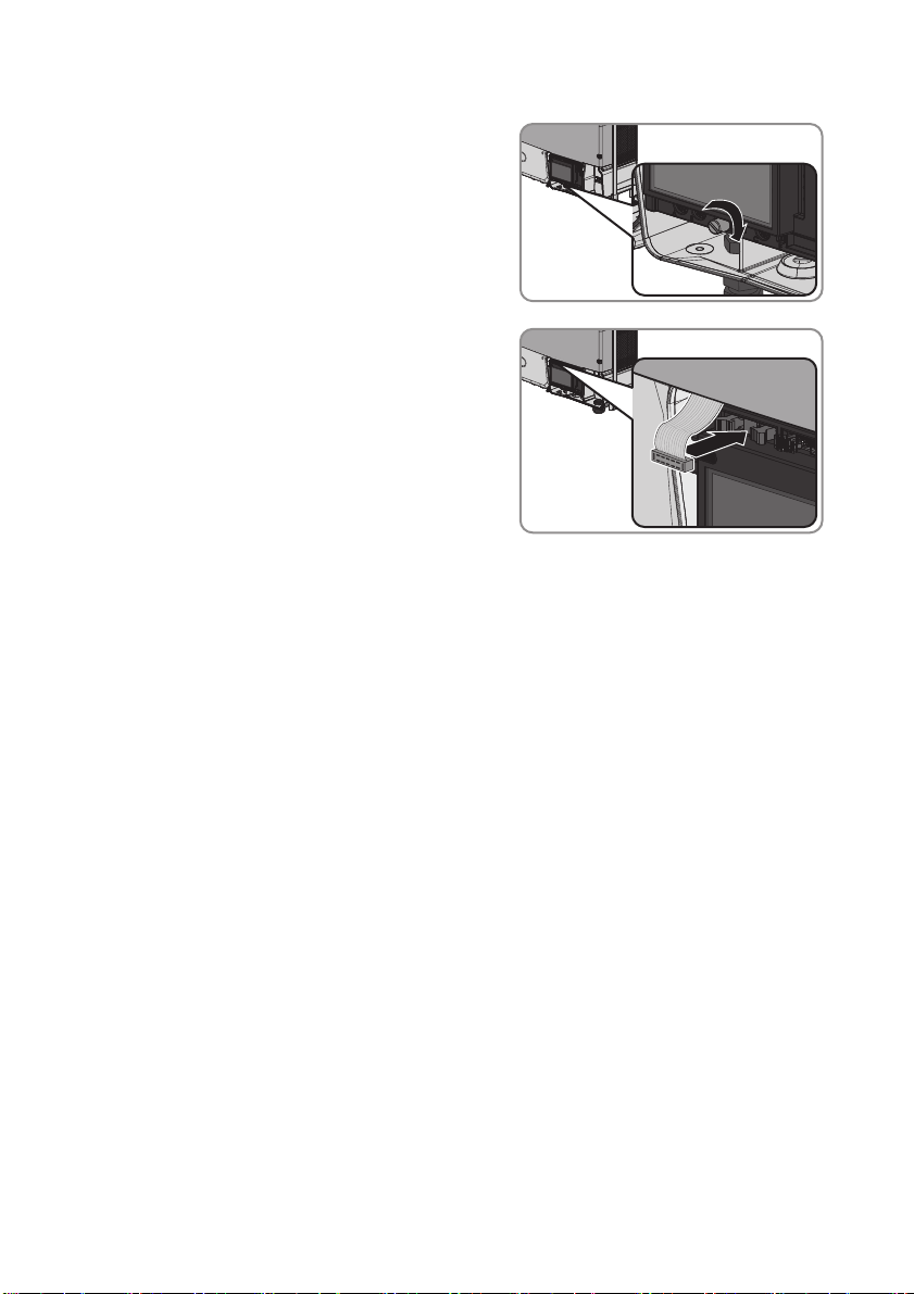
2. Flip up the display. Loosen the screw on the display.
☑ The display clicks into place.
Item Description
AInverter display
B Installation location of the multi-function relay
C Cable route for the connection to the multi-function relay
D M20x1.5 cable gland
Graphics
This section describes the installation of the multi-function relay using the Sunny Tripower as a
graphical example. The installation is identical for the following inverter types:
Sunny Tripower, Sunny Boy and Windy Boy. The only difference is the inverter environment.
5 Electrical Connection SMA Solar Technology AG
14 MFR-NR-IA-en-20 Installation Manual
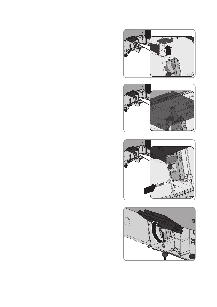
3. Insert the multi-function relay in the inverter. To do
this, insert the left-hand keyway at the top of the
multi-function relay into the cutout of the plastic
retainer of the inverter display.
4. Lead the ribbon cable upwards behind the display.
5. Fasten the multi-function relay using the washer and
the cheese-head screw (torque 1.5 Nm). For this
purpose, use an Allen key (AF 3).
6. Flip the display down.
SMA Solar Technology AG 5 Electrical Connection
Installation Manual MFR-NR-IA-en-20 15
7. Fasten the screw of the display hand-tight.
8. Insert the ribbon cable into the left socket on the
display of the inverter.
5.4 Multi-Function Relay Connection
5.4.1 Connection Options for the Multi-Function Relay
You can choose between three connection options:
• Using the multi-function relay as fault indication relay or operation signalling contact
• Controlling loads or charging batteries in a power-dependent way via the multi-function relay
• Reporting switching status of grid relay
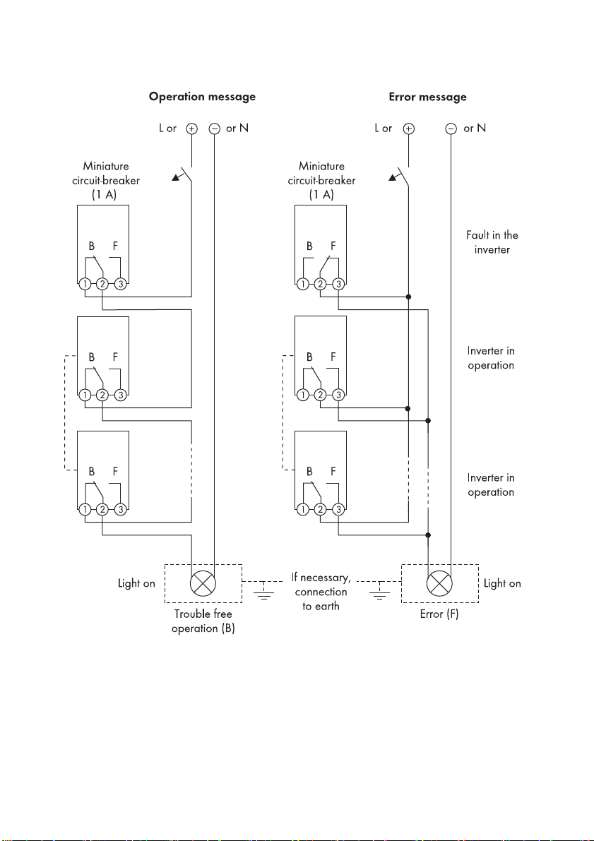
Using the Multi-Function Relay as Fault Indication Relay or Operation Signalling
Contact
You can make use of the multi-function relay as a fault signalling contact and have an error of the
inverter either displayed or reported. Alternatively, you can choose to have uninterrupted operation
displayed or reported. It is possible to connect several inverters to one fault or operation indicator.
To enable this function, the multi-function relays of several inverters must be switched in parallel.
5 Electrical Connection SMA Solar Technology AG
16 MFR-NR-IA-en-20 Installation Manual
Figure5: Wiring diagram with several inverters for connection of operation indicator and fault indicator
(example)

SMA Solar Technology AG 5 Electrical Connection
Installation Manual MFR-NR-IA-en-20 17
Controlling Loads or Charging Batteries in a Power-Dependent Way via the
Multi-function Relay
Loads can be controlled and batteries charged in a power-dependent way via the multi-function relay.
To enable this function, you need to connect a contactor (K1) to the multi-function relay. The contactor
(K1) switches the operating current for the load on or off. If you want batteries to be charged
depending on the available power, the contactor serves to activate or deactivate the charging of the
batteries.
Figure6: Wiring diagram for connection to control a load or for the power-dependent charging of the batteries

5 Electrical Connection SMA Solar Technology AG
18 MFR-NR-IA-en-20 Installation Manual
Reporting Switching Status of Grid Relay
The multi-function relay can trip a signal to the network operator as soon as the inverter connects to
the electricity grid. To enable this function, the multi-function relays of all inverters must be switched in
parallel.
Figure7: Wiring diagram for reporting the switching status of the grid relay (example)

SMA Solar Technology AG 5 Electrical Connection
Installation Manual MFR-NR-IA-en-20 19
5.4.2 Connection to the Multi-Function Relay
Requirements:
☐ The technical requirements of the multi-function relay must be met (see Section7 "Technical
Data", page23).
Cable requirements:
☐ The cable must be double-insulated.
☐ External diameter: 5 mm … 12 mm
☐ Conductor cross-section: 0.08 mm² ... 2.5 mm²
☐ The cable type and cable-laying method must be appropriate to the application and location.
1. When connecting to the electricity grid, protect the multi-function relay with an individual
miniature circuit-breaker.
2. Disconnect the inverter from any voltage sources (see the inverter installation manual).
3. If the cable gland on the inverter is installed inwardly, insert the cable gland from the outside.
• Unscrew the counter nut from the outside of the
inverter and remove the cable gland from the
inside of the inverter.
Destruction of the multi-function relay as a result of excessive contact load
• Adhere to maximum switching voltage and maximum switching current (see Section7
"Technical Data", page23).
• When connecting the multi-function relay to the electricity grid, protect the multi-function relay
with an individual miniature circuit-breaker.
Graphics
This section describes the connection to the multi-function relay using the Sunny Tripower as a
graphical example. The connection to the multi-function relay is identical for the following
inverter types: Sunny Tripower, Sunny Boy and Windy Boy. The only difference is the inverter
environment.

5 Electrical Connection SMA Solar Technology AG
20 MFR-NR-IA-en-20 Installation Manual
• Insert the cable gland from the outside into the
enclosure opening and tighten it from the inside
using the counter nut.
4. Slightly loosen the swivel nut of the cable gland and remove the sealing plug.
5. If the diameter of the connection cable is more than 8 mm, remove the internal seal insert from
the cable gland.
6. Route the cable into the inverter through the cable gland.
7. Strip the the cable jacket by a maximum of 15 mm.
8. Strip 8 mm of the conductor insulation at maximum.
9. Depending on the intended use (operating mode),
connect the cable to the terminal plate for
connection to the multi-function relay in accordance
with the wiring diagram.
10. Tighten the swivel nut of the cable gland.
11. Flip the display down.
Table of contents


