TIS EPC300A Assembly instructions

Electric Pressure / Vacuum Tester
Model: EPC300A
User Reference Manual

2
Introduction
The TIS Electric Pump Pressure Calibrator EPC300A combines the high accuracy of digital electronics with
the convenience and ease of use of an analog test gauge. Accurate to ±0.025% FS is standard, optional to
0.01% F.S. With high resolution of 5 full digits, this Calibrator can be used as a calibration reference or in
any application where high accuracy pressure measurement is required.
.
1.1 Customer Service
Corporate Office:
www.tiscalibrator.com
e-mail: sales@tisinstruments.com
Tel: (65) 6779-9272 Fax: (65) 6873-8262
TIS Instruments (s) Pte Ltd
8 @ Tradehub 21, #06-16 Boon Lay Way
Singapore 609964
1.2 Standard Equipment
Check to see that your TIS Leak Pressure Tester EPC300A has arrived intact. Save the packing materials at
least until you have verified that there is no concealed damage.

3
Misuse
Should the TIS Pressure Calibrator be exposed to overpressure or sudden physical shock (i.e. being
dropped) it should be examined for any damage that may cause a safety concern. If in doubt please return
the unit for evaluation to TIS Instruments. Please refer to the Customer Service Section for contact
information.
Caution
To avoid possible damage to calibrator or to equipment under test:
•Do not over pressure the EPC300A or unit under test
•Keep/ store the unit in cool dry place.

4
EPC300A Front Panel Layout
5
Startup
Power: TIS Electric Pump Pressure Calibrator is supplied with 14.8Vdc@4000mAH re-chargeable Li-ion
batteries installed.
Display battery voltage. Bar-graph indicates actual battery voltage condition. Re-charge when it reaches
25%.
To switch ON the unit, flip the ON/OFF switch to DOWN position. To switch OFF the unit, flip the ON/OFF
switch to UP position.
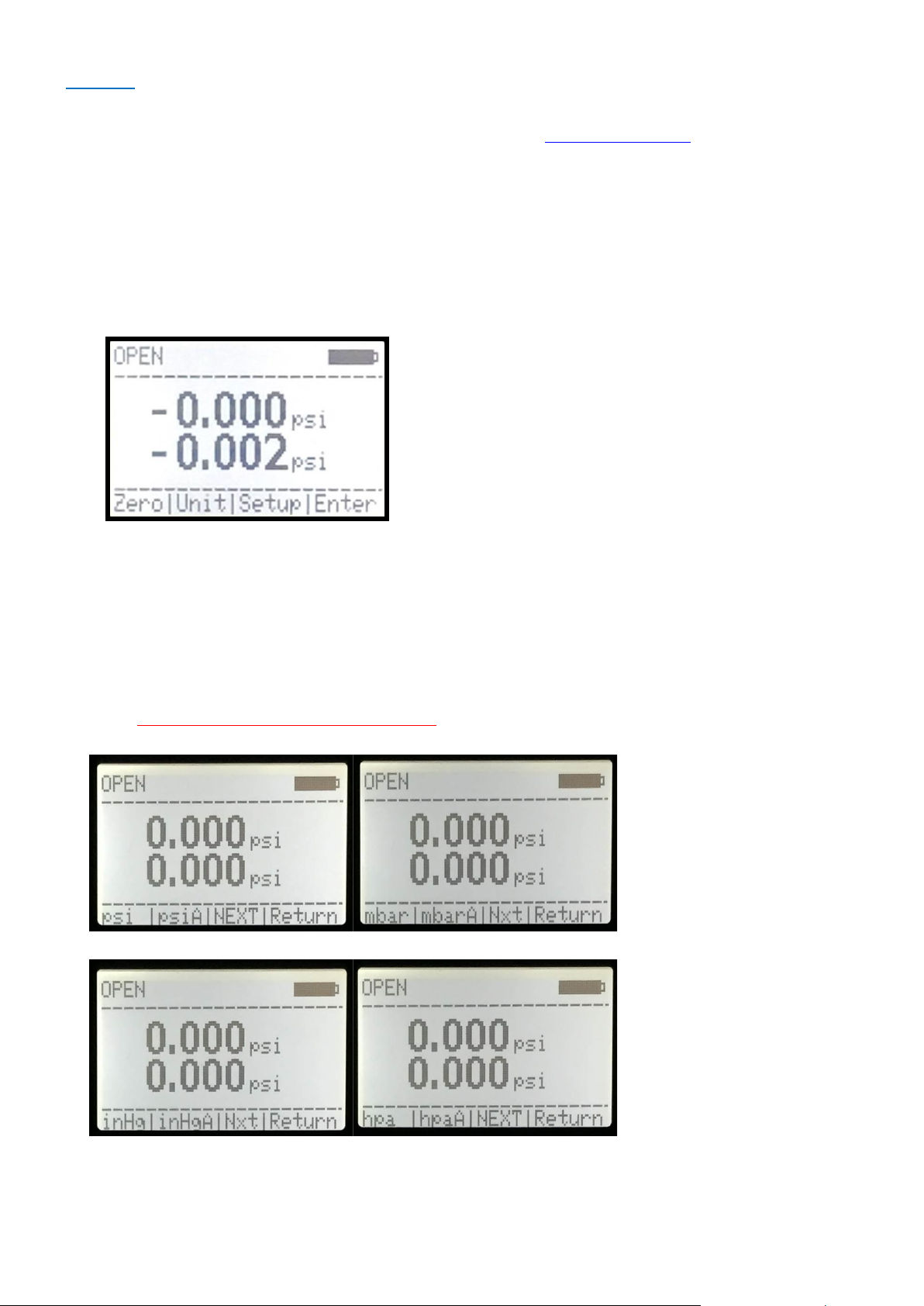
Upon power on, display shown the main menu, refer to Fig 1.0.
Main menu, Fig 1.0
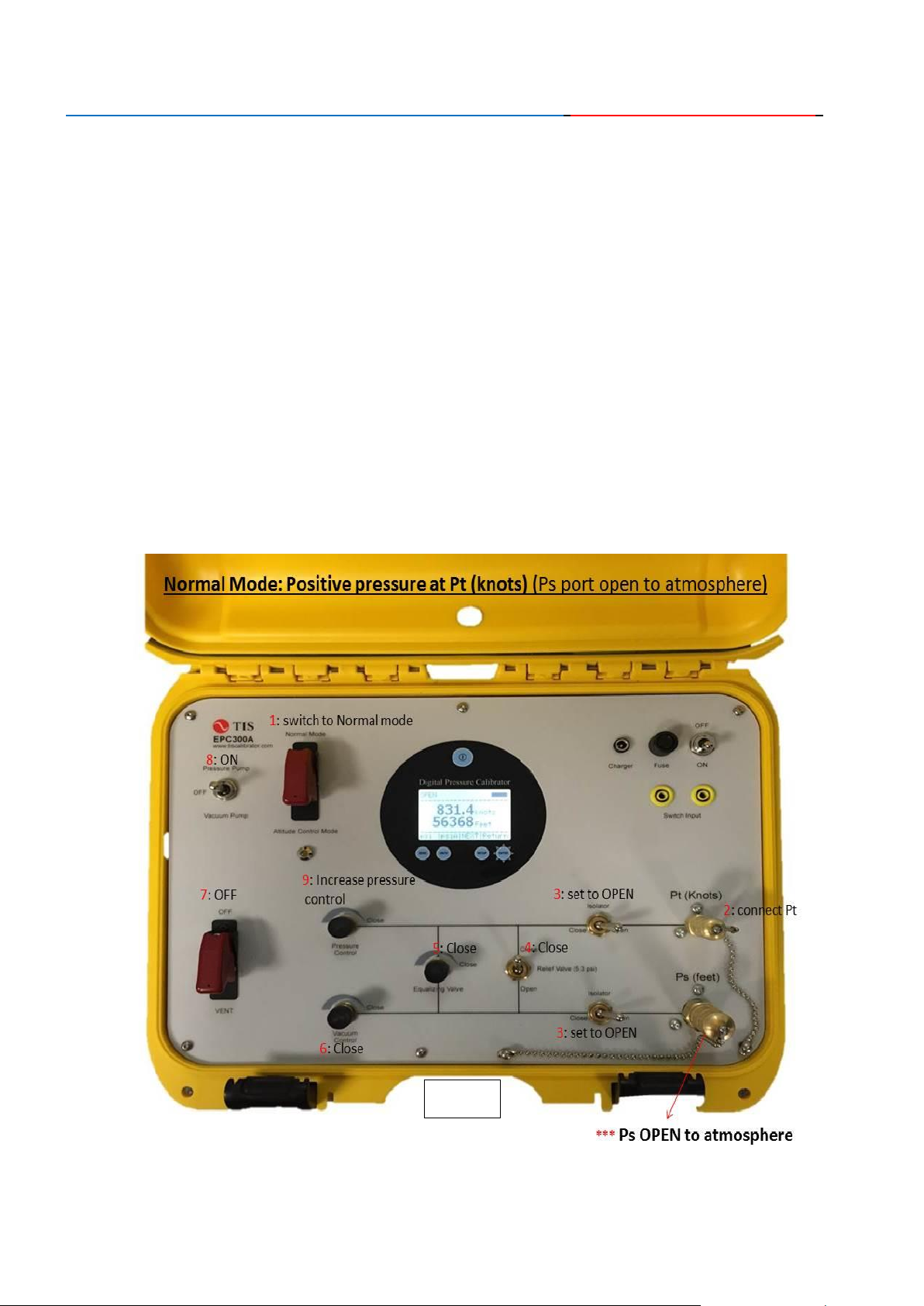
1. Engineering Units Selection:
By pressing the Unit key (Fig 1.0), and Next (Fig 1.1) key, User can scroll forward through the 10 standard
engineering units. When the desired unit is displayed, press the key corresponds to Unit display. Pressure will
now be displayed in the chosen engineering units
Note: Line 2 (Ps, feet): do not have knots unit.

6
Unit Selection, Fig 1.1
2. Set ZERO/TARE reading in GAUGE mode only (Line 1, Pt knots).
a) Vent the system by switching the x2 isolator valves to OPEN position, anti-clockwise about 3-5 turns
both the Pressure and Vacuum control knob, switch on the VENT valve
b) Select Line 1 psi (gauge mode).
c) Wait for few seconds to stabilize the pressure, press PSI 1 + RET keys concurrently (Fig 2.0)
d) Line 1 should now read 0.000 psi ±0.001.
3. Set ZERO/TARE reading in GAUGE mode only (Line 2, Ps feet).
a) Vent the system by switching the x2 isolator valves to OPEN position, anti-clockwise about 3-5 turns
both the Pressure and Vacuum control knob, switch on the VENT valve
b) Select Line 2 psi (gauge mode).
c) Wait for few seconds to stabilize the pressure, press PSI 2 + RET keys concurrently (Fig 2.0)
d) Line 2 should now read 0.000 psi ±0.001.
Note: To increase accuracy of the measurement. When the reading is >=0.005 psig in VENT
mode, user need to re-zero reading of Line 1 and Line 2 when selected either psi, mbar, inHg,
hPa unit;
Zero key is disable when user selected Absolute, knots or feet unit.
Line 1 or Line 2 zero selection, Fig 2.0
7
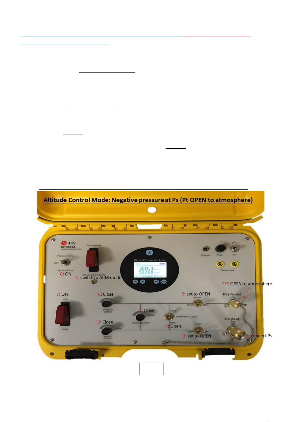
Normal Mode (Fig 3.0): Positive pressure at Pt (knots) (Ps port open to atmosphere)
1. Switch to Normal Mode
2. Connect the Pt port via pressure hose to the U.U.T/D.U.T
3. Set both Isolator valve to OPEN position
4. Set Relief valve to CLOSE position
5. Close the Equalizing valve by turning knob fully clock-wise, do not over torque, hand tight is good
enough.
6. Close both Pressure and Vacuum Control metering valve by turning knob fully clock-wise, do not
over torque, hand tight is good enough.
7. Switch OFF VENT valve
8. Switch on the internal Pressure Pump
9. Open the Pressure Control metering valve slowly anti-clock-wise to increase pressure.
10. CLOSE the Pressure Control metering valve Switch OFF the internal pump when pressure reaches
set point.
11. If require, CLOSE both the isolator valves.
12. To VENT the system, switch the x2 isolator valves to OPEN position, switch on the VENT valve
and open the Pressure Control metering valve slowly anti-clock-wise to vent pressure.
Fig 3.0

8
Normal Mode (Fig 4.0): Negative pressure at Ps (feet) (Pt port open to atmosphere)
1. Switch to Normal Mode
2. Connect the Ps via pressure hose to the U.U.T/D.U.T
3. Set both Isolator valve to OPEN position
4. Set Relief valve to CLOSE position
5. Close the Equalizing valve by turning knob fully clock-wise, do not over torque, hand tight is good
enough.
6. Close both Pressure and Vacuum Control metering valve by turning knob fully clock-wise, do not
over torque, hand tight is good enough.
7. Switch OFF VENT valve
8. Switch on the internal Vacuum Pump
9. Open the Vacuum Control metering valve slowly anti-clock-wise to increase vacuum level.
10. CLOSE the Vacuum Control metering valve and Switch OFF the internal pump when vacuum
reaches set point.
11. If require, CLOSE both the isolator valves.
12 To VENT the system, switch the x2 isolator valves to OPEN position, switch on the VENT valve
and open the Vacuum Control metering valve slowly anti-clock-wise to vent vacuum pressure.
Fig 4.0

9
Normal Mode (Fig 5.0): Negative pressure at Ps and Pt
1. Switch to Normal Mode
2. Connect the Pt and Ps via pressure hose to the U.U.T/D.U.T
3. Set both Isolator valve to OPEN position
4. Set Relief valve to OPEN position (10 inHg differential pressure protection)
5. Close the Equalizing valve by turning knob fully clock-wise, do not over torque, hand tight is good
enough.
6. Close both Pressure and Vacuum Control metering valve by turning knob fully clock-wise, do not
over torque, hand tight is good enough.
7. Switch OFF VENT valve
8. Switch on the internal Vacuum Pump
9. Open the Vacuum Control metering valve slowly anti-clock-wise to increase vacuum level. Control
Equalizing valve for Pt pressure as required.
10. Switch OFF the internal vacuum pump and CLOSE the Vacuum Control metering valve when
vacuum reaches set point.
11. If require, CLOSE both the isolator valves.
12 To VENT the system, switch the x2 isolator valves to OPEN position, switch ON the VENT valve,
open Equalizing valve slowly to equalize the pressure between Pt and Ps. When both Pt and Ps
pressure equalize, open the Pressure Control metering valve slowly anti-clock-wise to vent vacuum
pressure.
Fig 5.0
10
Altitude Control Mode (Fig 6.0): Negative pressure at Ps (Pt open to atmosphere)
Air Speed Indicator / Altimeter
1. Switch to Altitude Control position (Line 1, Pt display knot)
2. Select Line 2 unit to Feet
3. Connect the Ps (Pt open to atmosphere) via pressure hose to the U.U.T/D.U.T
4. Set both Isolator valve to OPEN position
5. Set Relief valve to OPEN position (10 inHg differential pressure protection)
6. Close the Equalizing valve by turning knob fully clock-wise, do not over torque, hand tight is good
enough.
7. Close both Pressure and Vacuum Control metering valve by turning knob fully clock-wise, do not
over torque, hand tight is good enough.
8. Switch OFF VENT valve
9. Switch on the internal Vacuum Pump
10. Open the Vacuum Control metering valve slowly anti-clock-wise to increase both knots and feet
reading.
11. Switch OFF the internal vacuum pump and CLOSE Vacuum Control metering valve when readings
reaches set point.
12. If require, CLOSE both the isolator valves.
13. To VENT the system, switch the x2 isolator valves to OPEN position, switch ON the VENT valve
and open the Vacuum Control metering valve slowly anti-clock-wise to vent vacuum pressure.
Note: Knots automatically display on Line 1(only knot in this mode). Select Line 2 unit to feet
Fig 6.0

11
Altitude Control Mode (Fig 7.0): Negative pressure at Ps and Pt
Air Speed Indicator/ Altimeter (Control Equalizing Valve for airspeed)
1. Switch to Altitude Control position
2. Connect both Ps and Pt via pressure hose to the U.U.T/D.U.T
3. Set both Isolator valve to OPEN position
4. Set Relief valve to OPEN position (10 inHg differential pressure protection)
5. Close the Equalizing valve by turning knob fully clock-wise, do not over torque, hand tight is good
enough.
6. Close both Pressure and Vacuum Control metering valve by turning knob fully clock-wise, do not
over torque, hand tight is good enough.
7. Switch OFF VENT valve
8. Switch on the internal Vacuum Pump.
9. Open the Vacuum Control metering valve slowly anti-clock-wise to increase both knots and feet
reading. Control Equalizing valve for various airspeed.
10. Switch OFF the internal vacuum pump and CLOSE Vacuum Control metering valve when readings
reaches set point.
11. If require, CLOSE both the isolator valves.
12. To VENT the system, switch the x2 isolator valves to OPEN position, switch ON the VENT valve,
open the Equalizing valve slowly to equalize the pressure between Pt and Ps. When both Pt and Ps
pressure equalize, open the Pressure Control metering valve slowly anti-clock-wise to vent vacuum
pressure.
Fig 7.0

12
Pressure Switch Test
1. To test the switch status, connect the normally open or normally close U.U.T/ D.U.T wires onto the
front panel marked Switch Input. (Non-voltage input only)
2. Switch status reading OPEN or CLOSE is display at the top left hand corner.
Note: Do not connect any external voltage to these terminal

13
Specifications
Pressure/Altitude/Airspeed Specification
Parameter
Operating Range
Resolution
Accuracy
Pt Sensor
-30 to 60 inHg
0.001
0.025% F.S
Ps Sensor
-30 to 60 inHg
0.001
0.025% F.S
Barometric Sensor
22 - 35 inHgA
0.001
0.025% Reading
Altitude (Ps)
-2000 to 50,000 ft
1 ft
3 ft @ 1000 ft
7 ft @ 10,000 ft
50 ft @ 40,000 ft
Airspeed (Pt)
10 to 800 knots
0.1 knots
±0.5 knots
Other Specification
Temperature Compensation
15 –45 °C to rated accuracy
Selectable Engineering Units
Knots, Feet, mbar, psi, inHg, hpa, mbarA, psiA, inHgA, hpaA
Display Type
L.C.D Graphic Module, 128x4 dots
Display Information
Line1(Pt) and Line2 (Ps)
Line 1 and Line 2 display both Feet reading
Pressure Generation
Built-in electric pressure pump(self-generate), 30 psig
Vacuum Generation
Built-in electric vacuum pump(self-generate), 95% vacuum
Relief Valve Protection Internal
10inHg between Pt and Ps line
Pressure Outlet
x2 1/8”FNPT. Eaton quick connect B1K11 (1/4”FNPT)
Eaton quick connect plug B2K16 (1/8”FNPT)
Switch Input
Non Voltage Input, N.O or N.C type
Display “OPEN” or “CLOSE” switch status
General Specification
Warm up time
5 minutes
Size
390x310x170 mm (Nanuk 915 case)
Weight
7.5 kg
Power
14.8Vdc @ 4AH Li-ion Battery
Charge / operating hours
4 hours per charge, 10 hours continuously use
Local Factory Warranty
1 year (including parts and labor)
14
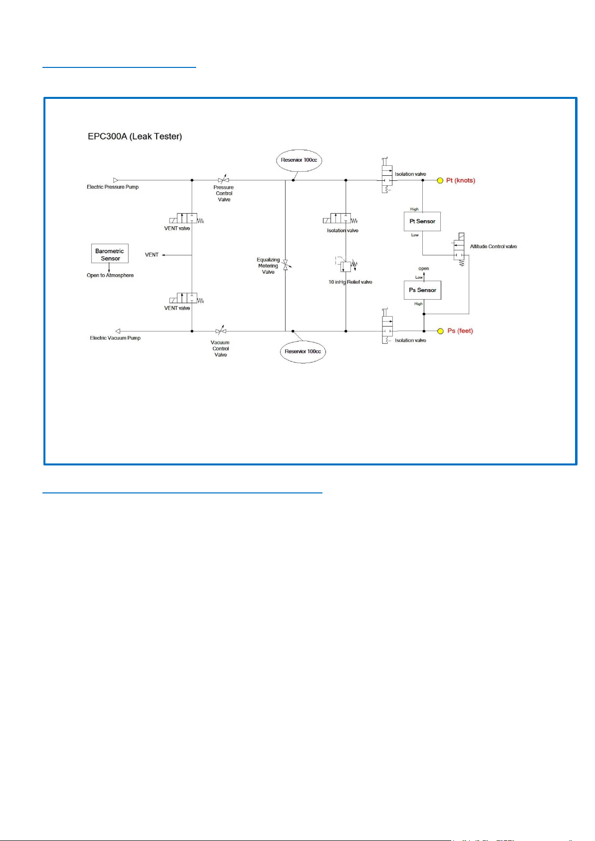
Pneumatic Circuit Diagram
Note: Pt (address 1), Ps (address 2), Baro (address 3)

15
Overview Re-Calibration
Calibration adjustment of the TIS Leak Pressure Tester EPC300A is performed electronically via internal software
with the case closed. There are no mechanical adjustments; all calibration commands and adjustments are done
via the keypad, using the display to guide the user through the calibration process.
Note: This is an ambient temperature calibration, and should be performed at an ambient temperature of 23°C ±
3°C (72°F ±5°F). Calibration outside this temperature range will invalidate the temperature compensation
program in the Leak Pressure Tester EPC300A.
Calibration Interval
You should check performance of the EPC300A at the interval required by your calibration program. We
recommend adjustment when measurement deviates by more than 0.025%.
Test Equipment
Verification and calibration of the TIS Pressure Calibrator EPC300A requires pressure and/or vacuum standards
able to produce and indicate pressures from vacuum to the full-scale range of the unit under test. In order to
maintain the specified accuracy of the EPC300A, reference standards should have a TUR of 4:1 or better.
Connections:
The EPC300A uses Eaton quick connect plug connection on the Pt/Ps ports. Various adapters may or may not be
needed to connect to the pressure standard. Always make sure the hose, tubing, and fittings etc have a rated
working pressure at or above the pressure of the unit. Also it is important that there be no leaks when performing
calibration; use Teflon tape where appropriate.
Calibration Sequence
The EPC300A has x3 pressure sensors installed. Calibration steps are as of below;
1) Pt (-atm to 30 psig @ 0.025% F.S).
2) Ps (-atm to 30 psig @ 0.025% F.S)
3) Barometer (22 to 35 in Hg Absolute)
Calibration Factor
Calibration span FACTOR is generated by dividing the reference full scale reading over the
U.U.T/D.U.T reading; (Reference F.S reading / U.U.T reading). Input this value into the correct sensor.
This span factor value typically falls within 0.99000 to 1.01000.
16
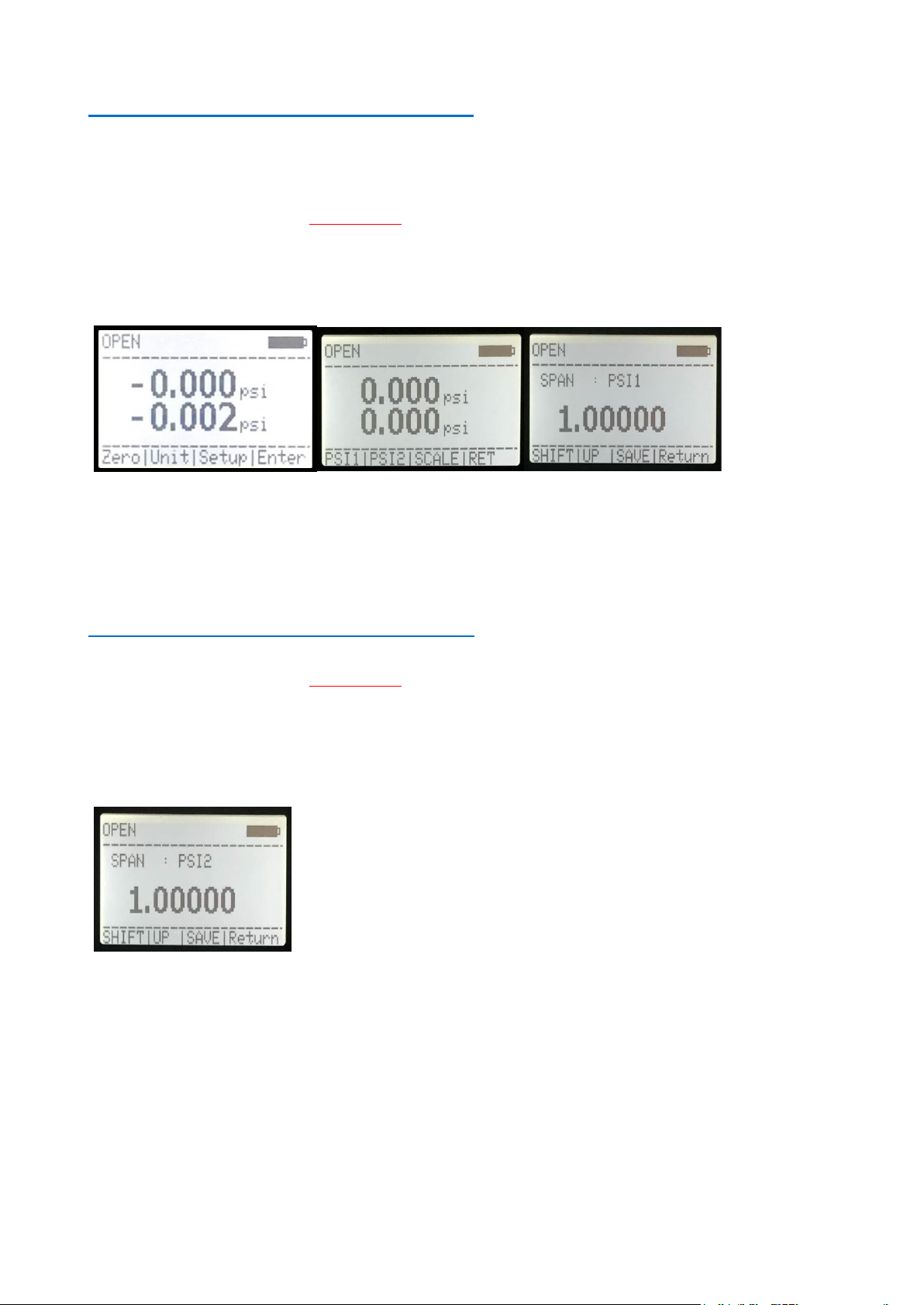
Entering Calibration Mode: Pt Sensor (Line 1)
a) Ensure Line1 and Line2 both in psig mode.
b) Press the ZERO key (Fig 8.0)
c) Press SCALE and RET concurrently (Fig 8.1)
d) Ensure that display read SPAN: PSI 1.(Fig 8.2)
e) Enter the span factor by pressing the UP key (change the value, flashing) and Shift key to shift digit left.
f) After completion, press SAVE key follow by Ret key. Calibration span factor has now saved in EEprom
of the CPU. Screen proceed to LINE 2 calibration, Fig 9.1
Fig 8.0 Fig 8.1 Fig 8.2
Entering Calibration Mode: Ps Sensor (Line 2)
a) Ensure that display read SPAN: PSI 2.(Fig 9.1)
b) Enter the span factor by pressing the UP key (change the value, flashing) and Shift key to shift digit left.
c) After completion, press SAVE key follow by Ret key. Calibration span factor has now saved in EEprom
of the CPU. Screen proceed to Barometer calibration, Fig 10.1
Fig 9.1

17
Calibration Mode: Barometric Sensor
a) Ensure that display read SPAN: PSI 3.(Fig 10.1)
b) Enter the span factor by pressing the UP key (change the value, flashing) and Shift key to shift digit left.
c) After completion, press SAVE key follow by Ret key. Calibration span factor has now saved in EEprom
of the CPU. Calibration Completed.
Note: Barometric reading is added to the Pt and Ps line.
Fig 10.1

18
Warranty:
TIS Instruments warrant all products against defects in material or workmanship for a period of 12 months from the
date of shipment. Problems or defects that arise as a result of abuse or misuse of the product are not covered. If a
product requires service, contact our customer service department for a “Return Materials Authorization” number.
This number must be indicated on the return package.
Be sure to package the product well, we are not responsible for damages caused by poor return
packaging.
Out-of-warranty repairs and recalibration will be subject to specific charges.
Under no circumstances will TIS Instruments be liable for any device or circumstance beyond the value of the
product.

19
This Page intentionally left blank

Table of contents
Other TIS Test Equipment manuals


