TIS 880 User manual

Network Cable Tester
Users Manual
Read this manual thoroughly before use
TIS 880


1
INTRODUCTION
The TIS 880 tester Is a small hand-held
cable tester, which enable network
professionals to quickly and easily verify
the integrity of straight-through, twisted
pair cables and coaxial cables. In addition,
the TIS 880 can test the ID number of the
ID test terminal connected to the remote
end of the cable under test so that this
cable can be verified.
Features
1. Tests UTP (Unshielded Twisted Pair),
STP (Shielded Twisted Pair) cable and
coaxial cable.

2
2. Checks continuity and configuration of
wiring with RJ45 plugs.
3. Tests for open circuits, shorts, miswires,
reversals, and split pairs.
4. Shield detection tests a cable's shield
integrity.
5. Debug mode quickly identifies which
cable pairs have a specific wiring fault.
6. Main unit and Remote unit allow one
person to test T568A, T568B,
10Base-T, and Token Ring cables.
7. Main unit is powered by two 1.5V
batteries and remote unit does not need
battery.
8. Low battery indication

3
STRUCTURE
1
2
3
4
5
6
7
8
9
10
11
12
13
14
Remote Unit
15 16
Main
Unit

Pair and SHIELD LEDs:
1. SHIELD/COAX LED
2. Pair 1-2 LED
3. Pair 3-6 LED
4. Pair 4-5 LED
5. Pair 7-8 LED
Fault Indicator LEDs:
6. " SHORT " LED
7. " MISWIRE " LED
8. " SPLIT PAIR " LED
9. " REVERSAL " LED
Others:
10. " LOW BATT " LED
11. Mode Selector Switch
12. TEST Key
13. BNC Socket of Main Unit
14. RJ45 Socket of Main Unit
15. RJ45 Socket of Remote Unit
16. BNC Socket of Remote Unit
4

5
Removing the Remote Unit:
Before remote test, you must remove the
Remote Unit from the Main Unit. To do it,
hold the Main Unit with a hand, use another
hand to hold the Remote Unit and slide it
upwards or downwards.
Slide the Remote
Unit upwards or
downwards.
Remote Unit
Main Unit
6
TYPICAL FAULTS
For straight-through cable or cross-over
cable tests, the tester has two operating
modes: Test mode and Debug mode.
In Test mode, a flashing pair LED indicates
that this wire pair has a fault, meanwhile a
fault indicator LED lights up to indicate
which fault was detected. Multiple flashing
pair LEDs indicate multiple pairs and/or
multiple faults. In this situation, you should
use Debug mode to diagnose the faults in
more detail. Correct the faults until the
cable is verified be to be correct by using
the tester.
A short circuit condition exists.
Short
Fault Details

Reversal
The pin for one wire in a pair is connected
to the opposite pin for this pair in the
remote jack.
Miswire
7
Split pairs occur when the tip (positive
Improper assignment of individual wire
pairs to pins for the wiring schemes tested.
Split Pairs

8
Note:
For some types of cables, so called
" OPEN " is not an abnormal condition.
Therefore the tester does not an " OPEN "
indicator LED. Open is displayed as an
unlit pair or shield LED when the tester
shows the test result. The user should
determine if a wire is present and
continuous or OPEN by comparing the
illuminated pair and/or shield LEDs with
the expected number of wires (of the cable)
that should be good.
During test, if the " LOW BATT " LED lights
up, the batteries in the Main Unit are low.
To avoid possible wrong test result, replace
the batteries immediately.
NOTICE PRIOR TO USE
1. Before using the tester, disconnect the
conductor) and ring (negative conductor)
of two twisted pairs are interchanged.

9
cable to be tested from any device;
otherwise the device may be damaged.
2. After test, the tester will turn off
automatically.
HOW TO TEST A STRAIGHT
-THROUGH CABLE
TEST Mode
1. Connect the Main Unit to one end of the
cable to be tested and the Remote Unit
to the other end of this cable.
2. For TIS 880, set the Mode Selector
Switch to the " Cable " position.
3. Press the TEST key and then release it.
The tester starts testing the cable. The
five green LEDs flash one time
sequentially from top to bottom, then the

tester shows the test result
-
flashing
pair LED indicates this pair has fault,
meanwhile fault indicator LED lights up
to indicate the fault.
4. The test will last about 12 secs, then
the tester will turn off automatically. At
any time, you can stop the test
manually by pressing the TEST key
again, the tester will turn off.
Example for TEST mode:
The cable fault is a SHORT on pair 1-2
and pair 3-6.
After the five green LEDs flash one time
sequentially from top to bottom, the tester
shows the following test results
simultaneously:
Pair 1-2 LED and pair 3-6 LED flash green,
meanwhile the " SHORT " LED lights red.
Pair 4-5 LED lights green indicating a good
pair.
Pair 7-8 LED lights green indicating a good
pair.
10

11
DEBUG Mode
The DEBUG mode identifies which cable
pairs have wiring fault. It cycles through
pairs displaying a test result for one pair at
a time. The fault is indicated by simultane-
ously lighting pair LED(s) and fault indicator
LED(s). A short flash on pair LED indicates
that the pair is under test, a long flash on
pair LED is the destination of test.
1. For TIS 880 set the Mode Selector
Switch to the " Cable " position. Then
press and hold the TEST key until all
LEDs light, then release the key.
2. The pair LEDs and the fault indicator
LEDs work together to identify which
pair is incorrect.
a. If a pair LED flashes two times in
series (one short and one long),
meanwhile no fault indicator LED
lights, the pair is wired correctly.

12
b. If a pair has fault(s), its pair LED will
give a short flash, then this pair LED,
other pair LEDs related to this pair's
fault(s), and the fault indicator LED(s)
will give a long flash simultaneously.
c. If a pair LED gives only a short flash
without a succedent long flash, this
pair has a OPEN fault.
3. After the DEBUG function cycles 4
times through the pairs, the tester will
turn off automatically. At any time, you
can stop the test manually by pressing
the TEST key again, the tester will turn
off.
Example for DEBUG mode:
The cable fault is a SHORT on Pair 1-2
and Pair 3-6.
The DEBUG mode LED series will be as
follows:
1. Pair 1-2 LED gives a short flash, then
pair 1-2 LED, pair 3-6 LED and the

13
" SHORT " red LED give a long flash
simultaneously.
2. Pair 3-6 LED gives a short flash, then
pair 3-6 LED, pair 1-2 LED and the
" SHORT " red LED give a long flash
simultaneously.
3. Pair 4-5 LED flashes two times in series,
meanwhile no fault indicator LED lights.
This indicates that this pair is wired
correctly.
4. Pair 7-8 LED flashes two times in series,
meanwhile no fault indicator LED lights.
This indicates that this pair is wired
correctly.
5. After the DEBUG function cycles
through the pairs 4 times, the tester will
turn off automatically.
14
HOW TO TEST A CROSSOVER
CABLE ( for EM2426 only )
The method of testing crossover cable is
almost the same as that of testing straight
-through cable, the only difference is:
The Mode Selector Switch is in the
" Standard " position when you test
straight-through cable; if you want to test
crossover cable, you must set the switch
in the " Cross Cable " position.
Refer to the " HOW TO TEST A STRAIGHT
-THROUGH CABLE " section and
remember to set the Mode Selector Switch
to the " Cross Cable " position for testing
crossover cable.
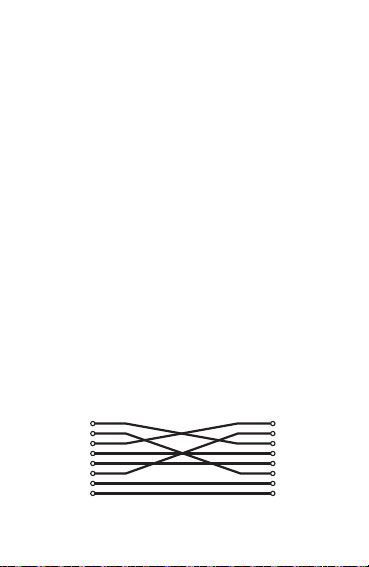
1
2
3
4
5
6
7
8
1
2
3
4
5
6
7
8
Crossover Cable Wiring

15
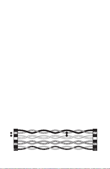
HOW TO TEST COAXIAL
CABLE
1. Connect one end of the coaxial cable to
be tested to the BNC socket of the Main
Unit and the other end of the coaxial
cable to the BNC socket of the Remote
Unit.
Note: The terminators on the cable to
be tested should match the BNC sockets
of the tester.
2. Press the TEST key and then release
it, the five green LEDs of the Main Unit
will flash one time sequentially from top
to bottom, then the tester shows the
test result:
If the " SHIELD/COAX " LED lights green,
the coaxial cable has no fault; if the
" SHIELD/COAX " LED does not light,
the cable is faulty.

Note:
For coaxial cable tests, the Mode Selector
Switch can be in any function position.
HOW TO VERIFY A CABLE
( for TIS 880 only )
1. Connect the Main Unit to one end of
the cable to be verified and ID test
terminals (optional) to other possible
ends of this cable.
2. Set the Mode Selector Switch of the
Main Unit to the " ID " position.
3. Press " TEST " key and then release
it, the " ID " LED display of the Main
Unit will show the ID number (1 - 8) of
the ID test terminal connected to the
cable under test, and the red LED on
this ID test terminal will flash once; so
this cable can be verified.
16

17
BATTERY REPLACEMENT
When the " LOW BATT " LED lights
continuously, the batteries are low and
should be replaced immediately.
1. Remove the screws on the back cover
of the Main Unit and remove the back
cover.
2. Replace the exhausted batteries with
new ones of the same type, make sure
that the polarity connections are correct.
3. Reinstall the back cover and the screws.
SPECIFICATIONS
Cable Length: Minimum: 1m
Maximum: 300m
Red LED
ID Test Terminal

18
DISPOSAL OF THIS ARTICLE
Dear Customer,
If you at some point intend to dispose of this
article, then please keep in mind that many
of its components consist of valuable
materials, which can be recycled.
Please do not discharge it in the garbage bin,
but check with your local council for recycling
facilities in your area.
V130704
NOTE
1. This manual is subject to change
without notice.
2. Our company will not take the other
responsibilities for any loss.
3. The contents of this manual can not be
used as the reason to use the tester for
any special application.
Battery: 1.5V battery, AAA or equivalent,
two pieces
Size: 98×64×58 mm (in storage state)
Weight: about 165g (including batteries)
Table of contents
Other TIS Test Equipment manuals


Popular Test Equipment manuals by other brands


Redtech
Redtech TRAILERteck T05 user manual

Venmar
Venmar AVS Constructo 1.0 HRV user guide

Test Instrument Solutions
Test Instrument Solutions SafetyPAT operating manual

Hanna Instruments
Hanna Instruments HI 38078 instruction manual

Kistler
Kistler 5495C Series instruction manual

Waygate Technologies
Waygate Technologies DM5E Basic quick start guide

StoneL
StoneL DeviceNet CK464002A manual

Seica
Seica RAPID 220 Site preparation guide

Kingfisher
Kingfisher KI7400 Series Training manual

Kurth Electronic
Kurth Electronic CCTS-03 operating manual

SMART
SMART KANAAD SBT XTREME 3G Series user manual

Agilent Technologies
Agilent Technologies BERT Serial Getting started