Titan Attachments 120STMPGRNDRv2 User manual

SKID STEER STUMP GRINDER
120STMPGRNDRv2
124117
Operator’s Manual
Read the Operator’s Manual entirely. When you see this
symbol, the subsequent instructions and warnings are
serious follow without exception. Your life and the lives
of others depend on it!
.

2
NOTE: The wiring harness comes installed with a 14-pin connector. This connector
contains the wiring for your power source. If your machine does not have a 14-pin plug,
simply remove this adapter to the expose the wires to connect to power source directly.
This implement MUST be connected to an electrical power source to operate all
functions properly.
IMPORTANT SAFETY INFORMATION
THESE ARE STANDARD PRACTICES THAT MAY NOT APPLY TO THE PRODUCTS
DESCRIBED IN THIS MANUAL.
SAFETY AT ALL TIMES
Thoroughly read and understand the instructions given in this manual before
operation. Refer to the “Safety Label” section, read all instructions noted on them. Do
not allow anyone to operate this equipment who has not thoroughly read and
comprehended this manual. Do not allow anyone who has not adequately trained in
the safe operation of the equipment.
•The operator should be familiar with all functions of the unit.
•Operate implement from the driver’s seat only.
•Make sure all guards and shields are in place and secured before operating the
tool.
•Do not leave a tractor or implement unattended with the engine running.
•Dismounting from a moving tractor could cause severe injury or death.
•Do not allow anyone to stand between tractor and implement while backing up
to implement.
•Keep hands, feet, and clothing away from power-driven parts.
•Wear snug-fitting clothing to avoid entanglement with moving parts.
•Watch out for wires, trees, etc., when raising implements. Make sure all persons
are clear of the working area.
•Turning the tractor too tight may cause implement to ride upon wheels. This
activity could result in injury or equipment damage.
•Do not carry passengers on the tool at any time.
LOOK FOR THE SAFETY ALERT SYMBOL
The SAFETY ALERT SYMBOL indicates a potential hazard to personal safety, and
individuals must take safety precautions. When you see this symbol, be alert and
carefully read the message that follows it. In addition to the design and configuration of
equipment, hazard control and accident prevention depend on the awareness, concern,
prudence, and proper training of personnel involved in the operation, transport,
maintenance, and storage.

3
BE AWARE OF SAFETY ALERT WORDS
DANGER: Indicates imminently hazardous practices. A situation that, if not avoided, will result in
death or severe injury. The signal word is limited to the most extreme situation, typically for
machine components that, for functional purposes, cannot be guarded.
WARNING: Indicates a potentially hazardous situation that, if not avoided, could result in death
or severe injury, and includes hazards that are exposed when guards remove. Use warnings to
alert against unsafe practices.
CAUTION: Indicates a potentially hazardous situation that may result in minor or moderate
injury if not avoided. It may also be used to alert against unsafe practices.
FOR YOUR PROTECTION
Thoroughly read and understand the “Safety Label” section, read all instructions noted on
them.
SHUTDOWN AND STORAGE
•Lower machine to the ground, put the tractor in park, turn off the engine, and remove
the key.
•Detach and store implements in an area where children typically do not play
USE SAFETY LIGHTS AND DEVICES
•Slow-moving tractors, self-propelled equipment, and towed implements can create a
hazard when driven on public roads. They are challenging to see, especially at night.
•Flashing warning lights and we recommend turn signals whenever driving on the public
road.
TRANSPORT MACHINERY SAFELY
•Comply with state and local laws
•The maximum transport speed for implement is 20 mph, DO NOT EXCEED. Never travel
at a rate that does not allow adequate control of steering and stopping. Some rough
terrain requires a slower speed.
•Sudden braking can cause a towed load to swerve and upset. Reduce speed if the towed
load is not equipped with brakes.
Use the following maximum speed – tow load weight ratios as a guideline:
•20 mph when weight is less than or equal to the weight of the tractor.
•10 mph when weight is double the weight of the tractor.
IMPORTANT: Do not tow a load that is more than double the weight of the tractor.

4
KEEP RIDERS OFF MACHINERY
•Riders obstruct the operator’s view; they could be struck by foreign objects or thrown
from the machine.
•Never allow children to operate equipment.
•Practice Safe Maintenance
•Understand procedure before doing work. Use proper tools and equipment; refer to
Operator’s Manual for additional information.
•Work in a clean, dry area
•Lower the implement to the ground, put the tractor in park, turn off the engine, and
remove the key before maintenance.
•Allow implement to cool completely.
•Do not grease or oil implement while it is in operation.
•Inspect all parts. Make sure details are in good condition and installed correctly.
•Remove the buildup of grease, oil, or debris.
•Remove all tools and unused parts from implementation before operation.
PREPARE FOR EMERGENCIES
•Be prepared if a fire starts.
•Keep a first aid kit and fire extinguisher handy
•Keep emergency numbers for doctor, ambulance, hospital, and fire department near the
phone.
WEAR PROTECTIVE EQUIPMENT
•Wear protective clothing and equipment appropriate for the job. Avoid loose-fitting
clothing.
•Prolonged exposure to loud noise can cause hearing impairment or hearing loss. Wear
suitable hearing protection such as earmuffs or earplugs.
•Operating equipment safety requires the full attention of the operator. Avoid wearing
radio headphones while operating machinery.
AVOID HIGH-PRESSURE FLUIDS HAZARD
•Escaping fluid under pressure can penetrate the skin causing severe injury.
•Avoid the hazard by relieving pressure before disconnecting hydraulic lines or
performing work on the system.
•Ensure all hydraulic fluid connections are tight and all hydraulic hoses and lines are in
good condition before applying pressure to the system.
•Use a piece of paper or cardboard, NOT BODY PARTS, to check for suspected leaks.
•Wear protective gloves and safety glasses or goggles when working with hydraulic
systems.
•If an accident occurs, see a doctor immediately. Remember, any fluid injected into the
skin must be treated within a few hours, or gangrene may result.

5
TIRE SAFETY
•Tire changing can be dangerous, and trained personnel should be the only ones using
correct tools and equipment.
•When inflating tires, use a clip-on chuck and extension hose long enough to allow you to
stand to one side and NOT in front of or over the tire assembly. Use a safety cage if
available.
•When removing and installing wheels, use wheel handling equipment adequate for the
weight involved.
AVOID ROLLOVER
The equipment may rollover, resulting in death or serious injury. To help prevent rollover:
•Travel at a slow speed.
•Avoid sharp turns & sudden movement on slopes.
•Carry stump grinder close to the ground.
•Avoid holes, ditches and other obstructions which may cause equipment to rollover.
•Use caution when operating on slopes and do not operate on excessively steep slopes.
•Do not exceed load capacity of equipment.
DO NOT ALLOW RIDERS
•NEVER lift or carry anyone on stump grinder.
•NEVER use stump grinder as a work platform.
•NEVER allow passengers on stump
AVOID POWER LINES & UNDERGROUND UTILITIES
DANGER!
•Prevent electrocution.
•Death or serious injury can result if equipment comes near or contacts power lines.
•Electrocution can occur without direct contact.
•Check clearance before raising equipment.
•Have local utilities locate and mark underground wires, cables, pipelines, and other
hazards before digging.
•DO NOT leave the operator’s seat if any part of the equipment contacts electric lines or
cables.
RAISED ATTACHMENT
WARNING!
•Crushing hazard.
•Raised, unsupported stump grinder can fall, resulting in death or serious injury.
•Never enter the area under a raised stump grinder.
•A raised stump grinder can lower unexpectedly, resulting in death or serious injury.
•NEVER enter area under a raised stump grinder.
•Lower stump grinder to ground, engage parking brake, shut off engine and remove key
before servicing.

6
DETACH STUMP GRINDER SAFELY
Detach stump grinder on a firm and level surface. Stump grinder may fall over if detached on
unlevel or soft surface.
TRANSPORT SAFELY
Carry stump grinder low. Travel slow and avoid slopes.
LOWER OPERATING SPEED
Keep stump grinder low and move at slow speeds on rough or uneven terrain.
OPERATION INSTRUCTIONS
•Operate all functions in an open area with skid steer in idle to get a good feel for the
controls.
•Quick-Attach must always be fully engaged and in the locked position.
•Keep bystanders away from equipment while in use.
•Always wear face or eye protection, safety shoes, and other protective equipment
•appropriate for the job.
•Do not operate, work on or around this machine while under the influence of alcohol,
drugs or if feeling ill.
•Always keep clear of moving machinery.
•Turn off machine before exiting operator station.
•It is your responsibility to operate this equipment safely. You must be familiar with the
equipment and all safety practices before use.
•Do not allow untrained or unqualified people to operate this equipment.
•Check the surrounding area for bystanders and clear them before starting the skid steer
or attachment.
•Before operating the attachment, always visually inspect and verify that the coupler lock
pins are fully engaged through the latch slots on the attachment plate.
ATTACHING AND DETACHING
1. Read and follow all safety instructions.
2. Attach skid steer to stump grinder. Verify pins
are secure in the correct position.
3. Connect hydraulic hoses. Verify hydraulic
hoses are clear of pinch areas. Case drain
hose must be connected!
4. Connect to 12V power source. Comes pre-
installed with 14-pin adapter; however, this can be removed to expose the wiring
needed for connecting to power source.
5. Move to a clear open area to test functions.

7
ROUTINE MAINTENANCE
REPLACE CUTTING TEETH
1. Support stump grinder to prevent falling.
2. Stop skid steer engine and remove key.
3. Inspect cutting teeth for damage. Rotated the tooth 3 times before replace it.
Replace individual teeth as needed.
1. Remove lock nut (1) and cutting tooth (2)
2. Rotated the tooth or install replacement tooth and lock nut. Tighten locknut (1) to 95
lb./ft. (129 Nm) of torque. Do not allow untrained or unqualified people to operate this
equipment.
INSPECTIONS
1. Check hydraulic hoses and fittings daily for leaks. Replace hose if worn or damaged.
2. Inspect the unit for any buildup of contamination (dirt, stones, etc.).
3. Check cutting teeth every 2 hours of use. Keep cutting teeth in good condition. Unit will
cut faster, and remaining teeth will last longer if broken teeth are replaced
8
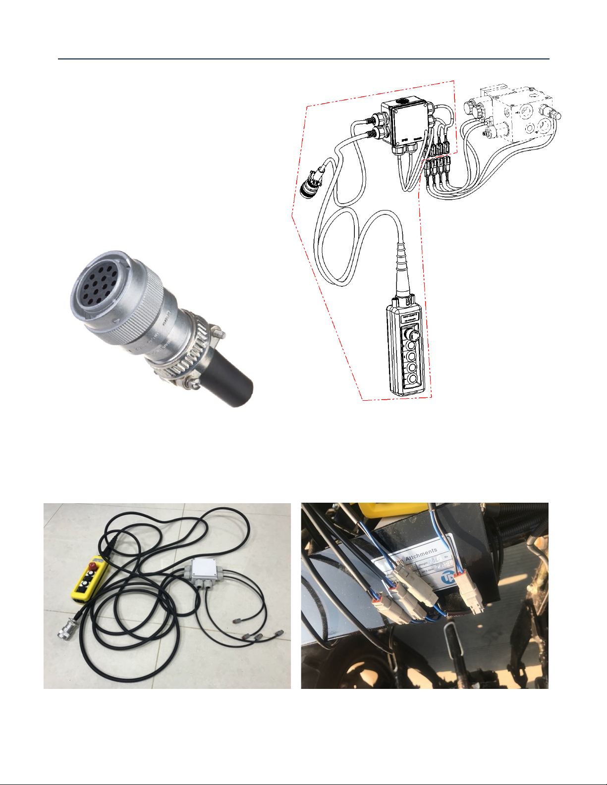
ELECTRICAL CONTROL HARNESS
ELECTRICAL CONTROL HARNESS
NOTE: This implement MUST be
connected to an electrical power
source to operate properly.
Show below is the 14-pin adapter that
comes installed. If your machine does
not have a 14-pin plug, simply remove
this piece to expose the wiring to
connect to a 12V power source.
Unit comes installed with 2-pin connectors that allow for simple connection/re-connection of
wiring harness and controller from the solenoids.

9
SPECIFICATIONS AND CAPACITIES
SPECIFICATIONS & CAPACITIES
120STMPGRNDv2
OVERALL LENGTH
72.3”
TELESCOPIC EXTENSION
11”
OUTPUT HEIGHT ABOVE GROUND
21.5”
OUTPUT HEIGHT BELOW GROUND
19”
OUTPUT TORQUE
100-120 LBS-FT
CUTTING WHEEL WIDTH
3.98”
CUTTING WHEEL DIAMETER
24”
CUTTING WHEEL SPEED
1100-1350 RPM
SWING RANGE
+/- 30°
TYPE OF TEETH
REVERSIBLE, ROTATED 3 TIMES
FORGED STEEL WITH CARBIDE FACE
NUMBER OF TEETH
16
DRIVELINE
GEAR MOTOR
HYDRAULIC FLOW
14-25 GPM
HYDRAULIC PRESSURE REQUIREMENT
2,320-3,000 PSI
NET WEIGHT
810 LBS.
GROSS WEIGHT
955 LBS.
PACKING SIZE
73” * 47” * 35”
VOLTAGE REQUIRED
12V DC

10
PARTS DIAGRAM/EXPLODED VIEW
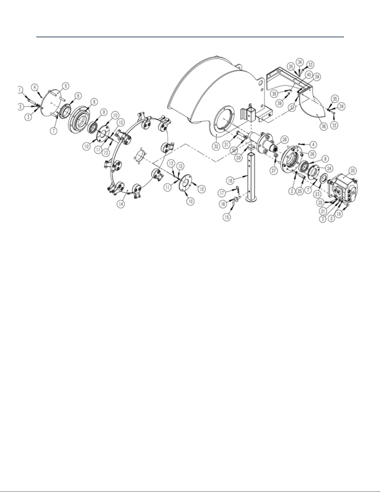
11
120STMPGRNDR PARTS DIAGRAM/EXPLODED VIEW

12
KEY BOX DESCRIPTION QTY KEY BOX DESCRIPTION QTY
1 GB/T 70.1 HEX SOCKET HEAD CAP
SCREW M12*65 4 40 SSG61.16 PRESS PLATE 02 1
2 GB/T 93 SPRING WASHER 12 11 41 GB/T 5783 BOLT M20*55 4
3 GB/T 97.1 FLAT WASHER 12 8 42 GB/T 97.1 FLAT WASHER 20 8
4 JB/T 7940.1 GREASE NIPPLE M6*1 5 43 GB/T 5783 BOLT M10*70 3
5 ESG47.5 COVER PLATE 1 44 SSG61.10 LIFTING FRAME 1
6 ESG47.7 BACKING PLATE 01 1 45 GB/T 6182 LOCK NUT M20 6
7 GB/T 70.3 HEX SOCKET HEAD CAP
SCREW M6*16
8 46 GB/T 6170 NUT M10 6
8 ESG47.6 BEARING SEAT 01 1 47 SSG61.20 PIN 1
9 GB/T 276-
2013
BEARING 6210-RS 2 48 SF-2X BEARING 3030 4
10 ESG47.8 BEARING SEAT COVER 4 49 SSG61.22 PIN01 1
11 GB/T 97.1 FLAT WASHER 6 8 50 JBT 7940.1-
1995 GREASE NIPPLE M8*1 8
12 GB/T 93 SPRING WASHER 6 8 51 SSG61.12 LINKAGE WELDMENT 1
13 GB/T 5783 HEX SCREW M6*20 8 52 GB/T889.1 NUT M24 1
14 SSG61.4 KNIFE DISH 1 53 GB/T 97.1 FLAT WASHER 24 1
15 EFGC175.37 LEG PIN 4 54 SSG61.19 PIN 2
16 GB/T 96 BIG WASHER 12 2 55 GB/T 97.1 FLAT WASHER 20 2
17 EFGC125.110 R PIN 3.2 4 56 GB/T889.1 NUT M20 2
18 SSG61.28 SUPPORT LEG 2 57 SSG61.21 PIN 1
19 GB/T 5783 BOLT M12*35 4 58 SSG61.23 PIN 02 1
20 CMZZ HYDRAULIC MOTOR 1 59 SSG61.17 SUPPORT LEG 2
21 GB/T 93 SPRING WASHER 10 12 60 GB/T 5783 BOLT M20*65 2
22 GB/T 70.1 HEX SOCKET HEAD CAP
SCREW M10*35 8 61 SSG61.27 SUPPORT MOUNT PLATE 2
23 GB
/
T13871.1 PLATE 50×80×8 1 62 GB/T 5783 BOLT M16*60 4
24 ESG47.11 BACKING PLATE 02 1 63 GB/T 6170 NUT M8 4
25 GB/T 70.1 HEX SOCKET HEAD CAP
SCREW M12*55
4 64 GB/T 5783 BOLT M8*50 2

13
26 ESG47.9 BEARING SEAT 02 1 65 SSG61.13 SKID STEER MOUNT
PLATE 1
27 GB/T 6182 LOCK NUT M16 8 66 WSG37.24 PIN 02 2
28 SSG61.3 SHAFT 1 67 SSG61.1 VALVE BLOCK 1
29 SSG61.33 LEG COVER 32*32 2 68 GB/T 97.1 FLAT WASHER 8 8
30 GB/T 97.1 FLAT WASHER 16 12 69 SSG61.26 VALVE MOUNT PLATE 1
31 GB/T 5783 BOLT M16*65 4 70 GB/T 6170 NUT M4 8
32 SSG61.2 THE COVER WELDMENT 1 71 GB/T 97.1 FLAT WASHER 4 4
33 GB/T 5783 BOLT M8*30 13 72 GB/T 823
CROSS RECESS HEAD
SCREW M4*70
4
34 GB/T 93 SPRING WASHER 8 13 73 GB/T 5783 BOLT M10*25 4
35 GB/T 97.1 FLAT WASHER 8 9 74 GB/T 97.1 FLAT WASHER 10 4
36 SSG61.14 RUBBER FLAP 1 75 GB/T 93 SPRING WASHER 6 1
37 SSG61.15 PRESS PLATE 01 2 76 SSG61.18 HYDRAULIC COMPONENTS 1
38 GB/T 96 BIG WASHER 8 2 77 SSG61.25 ELECTRICAL COMPONENT 1
39 GB/T 6170 NUT M8 14
14
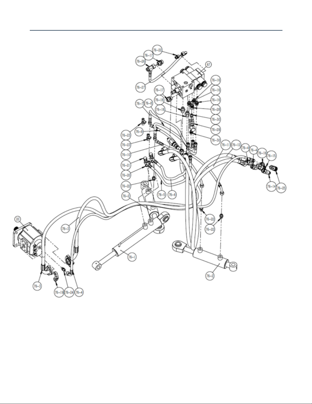
HYDRAULIC COMPONENT PARTS DIAGRAM/EXPLODED VIEW

15
KEY BOX DESCRIPTION QTY KEY BOX DESCRIPTION QTY
76-1 SSG61.18.1 LIFT CYLINDER 1 76-16 GE10LR3/8E
DOMD CONNECTOR M16*1.5-G3/8" 5
76-2 SSG61.18.2 SWING CYLINDER 2 76-17 GE18LR3/4E
DOMD CONNECTOR M27*1.5-G3/4" 2
76-3 SSG61.18-3 OIL HOSE 01 2 76-18 GE15LREDO
MD CONNECTOR M22*1.5-G1/2" 2
76-4 SSG61.18-4 OIL HOSE 02 1 76-19 ISO6161-1/-
2 FHS35/12SAE SPLIT FLANGE 4
76-5 SSG61.18-5 OIL HOSE 03 1 76-20 JBT 982 COMBINED WASHER 4
76-6 SSG61.18-6 OIL HOSE 04 1 76-21 GB/T 3750.3
BANJO BOLT M16X1.5 2
76-7
SSG61.18-7 OIL HOSE 05
1 76-22 GE10LM16X
1.5EDOMD
CONNECTOR M16*1.5-
M16*1.5
4
76-8 SSG61.18-8 OIL HOSE 06 1 76-23 EL10LOMD THREE-WAY CONNECTOR 2
76-9
SSG61.18-9
OIL HOSE 07
1 76-24
GE10LMEDO
MD
CONNECTOR M14*1.5-
M16*1.5
1
76-10
SSG61.18-10
OIL HOSE 08
1 76-25 KIS-PT-
G03SF
QUICK
-
CHANGE CONNECTOR
G3/8
1
76-11 SSG61.18-11
OIL HOSE 09 1 76-26 SSG61.18-14
THREE-WAY CONNECTOR 1
76-12 SSG61.18-12
OIL HOSE 10 1 76-27 SSG61.18-13
OIL HOSE 11 1
76-13 GE18LREDO
MD CONNECTOR G1/2-M27*1.5 2 76-28 EGE10LR3/8
ED
CONNECTOR
M16*1.5-G3/8" 1
76-14
KIS-PT-
G04SP
QUICK-
CHANGE CONNECTOR
G1/2 (MALE)
1 76-29
STU-1/4 CONTROL VALVE
1
76-15 KIS-PT-
G04SP
QUICK-
CHANGE CONNECTOR
G1/2 (FEMALE)
1 76-30
GEO10LR1/4
CONNECTOR M16*1.5-G1/4"
2
16
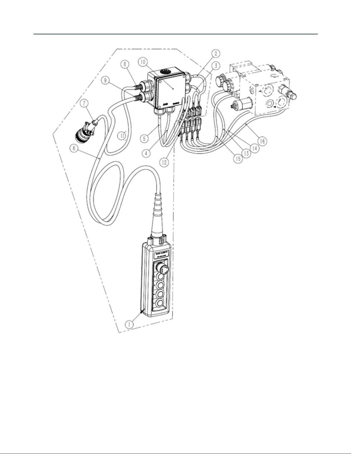
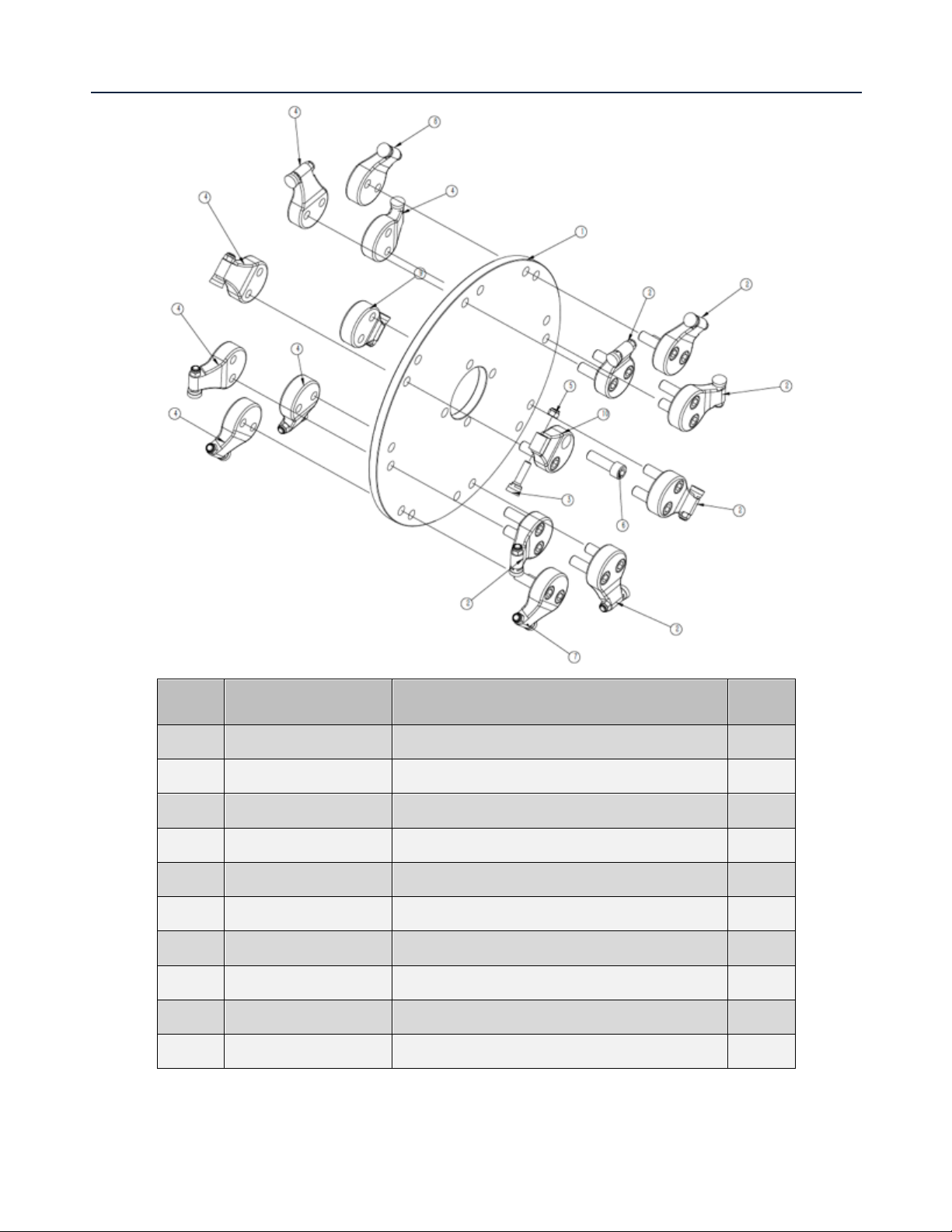
ELECTRICAL COMPONENT PARTS DIAGRAM/EXPLODED VIEW

17
KEY BOX DESCRIPTION QTY
1 XAC-A4813 BUTTON SWITCH 1
2 SSG61.25-1 ELECTRIC CABLE 01 1
3 SSG61.25-2 ELECTRIC CABLE 02 1
4 SSG61.25-3 ELECTRIC CABLE 03 1
5 SSG61.25-4 ELECTRIC CABLE 04 1
6 SSG61.25-5 ELECTRIC CABLE 05 1
7 HD36-18-14SN-059 14 PIN ADAPTERS 1
8 SSG61.25-7 CABLE CONDUIT 01 1
9 SSG61.25-8 CABLE CONDUIT 02 1
10 SSG61.25.9 JUNCTION BOXES 1
11 SSG61.25-6 ELECTRIC CABLE 06 1
12 DT06-2S 2 PIN ADAPTERS 4
13 SSG61.25-9 ELECTRIC CABLE 09 1
14 SSG61.25-10 ELECTRIC CABLE 10 1
15 SSG61.25-11 ELECTRIC CABLE 11 1
16 SSG61.25-12 ELECTRIC CABLE 12 1
18
ELECTRICAL COMPONENT PARTS DIAGRAM/EXPLODED VIEW
KEY BOX DESCRIPTION QTY
14-1 SSG61.4-7 CUTTING WHEEL 1
14-2 ESG47.4-2 TEETH BASE900-2 6
14-3 ESG47.4-8 TEETH 900 16
14-4 ESG47.4-3 TEETH BASE900-3 6
14-5 ASME B18.16.6 NYLON INSERT LOCK NUTS 16
14-6 ASME B18.3 HEX SOCKET HEAD BOLT 16
14-7 ESG47.4-4 TEETH BASE900-4 1
14-8 ESG47.4-5 TEETH BASE900-5 1
14-9 ESG47.4-6 TEETH BASE900-6 1
14-10 ESG47.4-1 TEETH BASE900-1 1

19
REPLACEMENT TEETH PARTS DIAGRAM/EXPLODED VIEW
KEY BOX DESCRIPTION QTY
14-3 ESG47.4-8 TEETH 900 16
14-5 ASME B18.16.6 NYLON INSERT LOCK NUTS 16

20
SKID STEER STUMP GRINDER ELECTRICAL SCHEMATIC DIAGRAM
Table of contents
Other Titan Attachments Industrial Equipment manuals


Popular Industrial Equipment manuals by other brands

hager
hager ARM U Series instruction manual

Mitsubishi Electric
Mitsubishi Electric BC34 Installation, operation & maintenance manual

Maschio
Maschio VELOCE PIEGHEVOLE Use and maintenance

Nexen
Nexen Air Champ S-450 user manual

Baltimore Aircoil Company
Baltimore Aircoil Company BCP3D Installation, Operating, Maintenance

JDS Uniphase
JDS Uniphase SWS15100 user manual


