Titan Attachments SKID STEER TRUSS BOOM v3 User manual
SKID STEER TRUSS BOOM v3
SSTRUSSBOOMv3
194153
Operator’s Manual
Read the Operator’s Manual entirely. When you see this
symbol, the subsequent instructions and warnings are
serious follow without exception. Your life and the lives
of others depend on it!

2
INTRODUCTION
•This manual is made at the time of manufacturing of the TRUSSBOOM that does not include
any subsequent modifications made afterward.
•This manual is intended to provide information to operators and owners to operate the
TRUSSBOOM safely and effectively, as well as to perform suitable maintenance for the
equipment.
•Before operating or performing maintenance of the equipment, it is critical to read,
understand and be acquainted with the operating, safety and maintenance
recommendations of this manual and the manual of your skid steer, or prime mover.
•Failure in operating and maintaining the TRUSSBOOM according to the instructions and
recommendations could lead to fatal accidence causing serious personal injury or death, as
well as damage to your equipment.
•Operators must conform with laws and regulations stipulated by OSHA as well as the local
applicable industrial safety regulations.
3
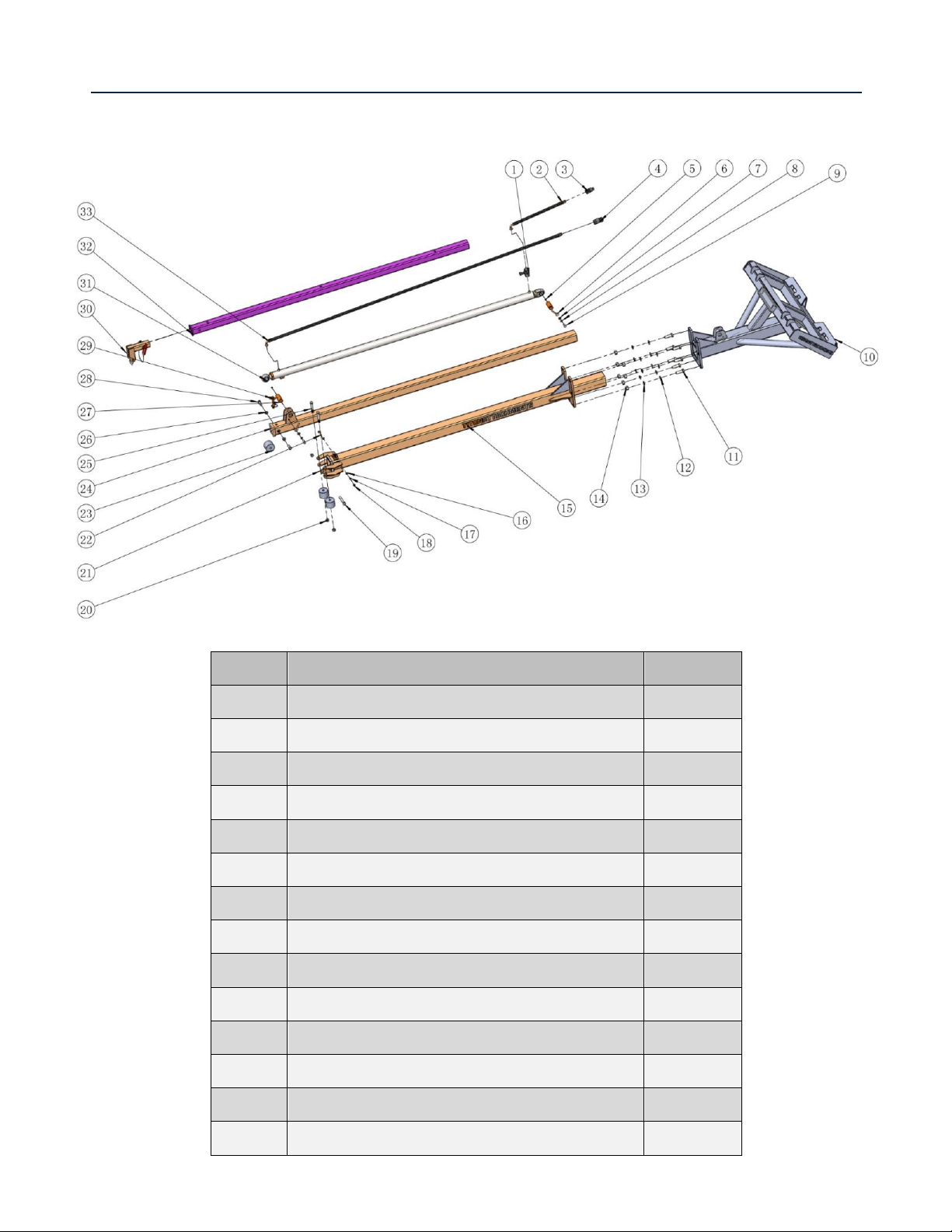
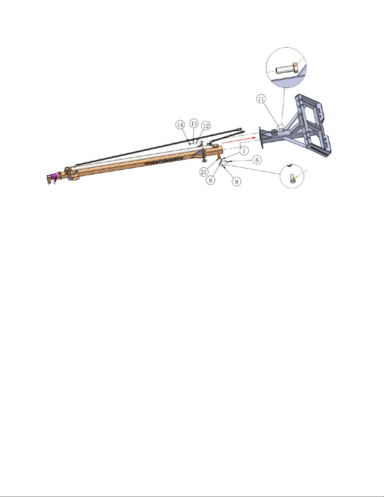
PARTS DIAGRAM / EXPLODED VIEW
KEY
DESCRIPTION
QTY
(1)
SAFETY VALVE
1
(2)
OIL HOSE - FEED
1
(3)
FLAT FACE COUPLER - MALE
1
(4)
FLAT FACE COUPLER - FEMALE
1
(5)
GREASE ZERK
2
(6)
EYE PIN
2
(7)
FLAT WASHER M12
2
(8)
SPRING WASHER M12
2
(9)
HEX BOLT M12x30
2
(10)
MAIN FRAME
1
(11)
HEX BOLT M20x60
7
(12)
FLAT WASHER M20
7
(13)
SPRING WASHER M20
7
(14)
HEX NUT M20
7

4
DESCRIPTION
SPECIFICATION
FULLY RETRACTED LENGTH:
134"
FULLY EXTENDED LENGTH:
313"
HYDRAULIC PISTON:
3" BORE X 90.5" STROKE
FULLY RETRACTED CAPACITY:
850 LB
FIRST EXTENSION CAPACITY:
520 LB
FULLY EXTENDED CAPACITY:
330 LB
PRODUCT WEIGHT:
612 LB
(15)
TITAN ATTACHMENT DECAL
2
(16)
FLAT WASHER M10
2
(17)
SPRING WASHER M10
1
(18)
HEX NUT M10
1
(19)
HEX BOLT M16x110
1
(20)
HEX LOCK NUT M16
2
(21)
TELEBOOM-1 (FIRST SECTION)
1
(22)
HEX BOLT M10x50
1
(23)
SLIDE ROLLER
3
(24)
TELEBOOM-2 (SECOND SECTION)
1
(25)
HEX BOLT M16x100
2
(26)
HEX NUT M16
2
(27)
CYLINDER PIN
2
(28)
HEX BOLT M16x40
2
(29)
LOCK PIN
1
(30)
HOOK ASSEMBLY
1
5
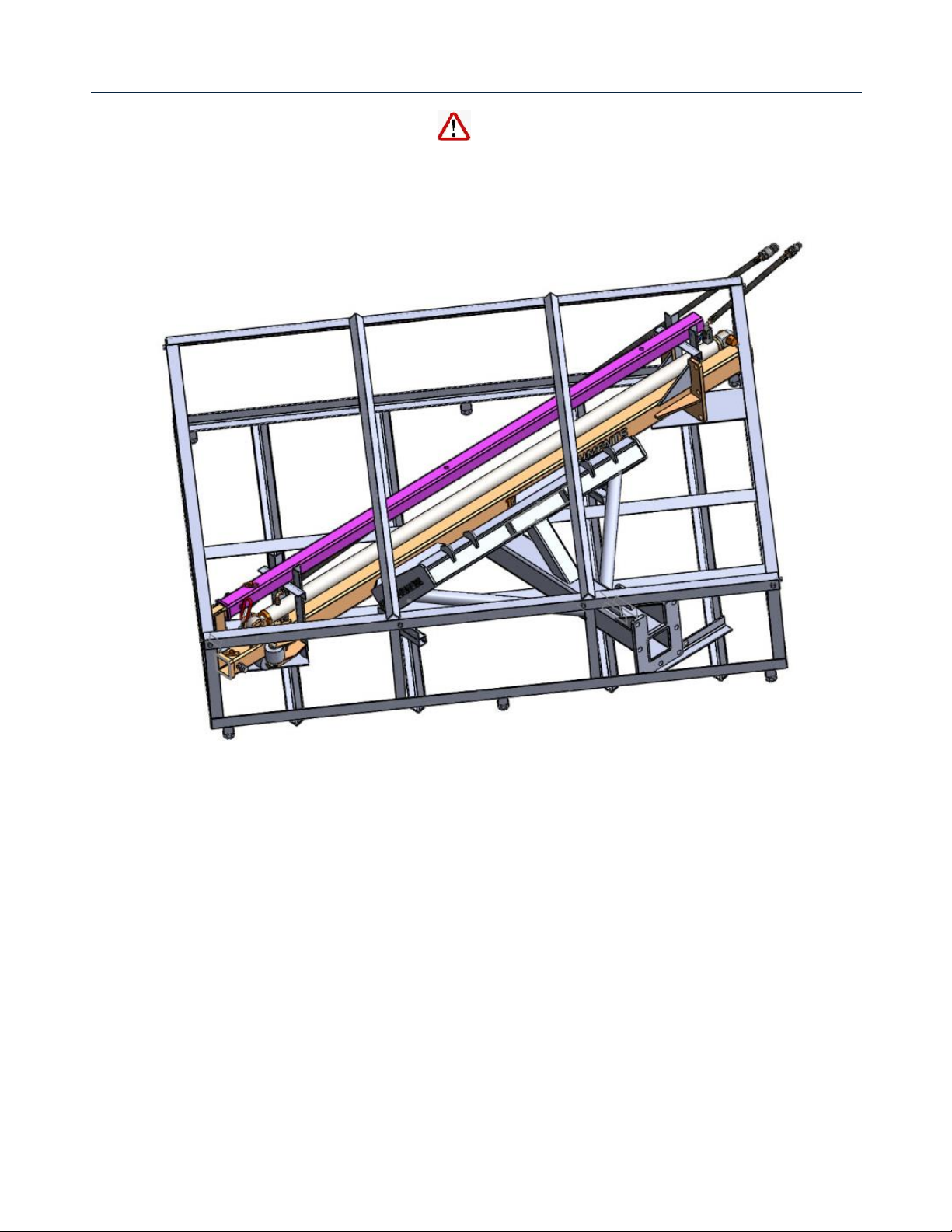
ASSEMBLY INSTRUCTIONS
1. REMOVE PARTS FROM STEEL CRATE
The fork blade used to lift the steel crate should be at least 2/3 of the length of the crate.
It is recommended that the left and right fork blades should move to the farthest ends.
Failure to do so may lead to imbalance causing the crate to slide out that may cause injury.
•Take off steel crate’s top panel, cut off wire tying the parts and take out TELEBOOM-3 (32)
(note that HOOK ASSEMBLY (30) is pre-installed on it).
•Take out TELEBOOM-2 (24) (note that TELEBOOM-1 (21), CYLINDER (31), OIL HOSE –FEED (2)
and OIL HOSE RETURN (33) are pre-installed as assembly).
•Take off steel crate’s side panels, cut off wire tying MAIN FRAME (10), and move skid steer
loader towards the mount plate of MAIN FRAME (10). Engage skid steer loader quick attach
arm to the mount plate of MAIN FRAME (10) and pick up the MAIN FRAME (10).
6
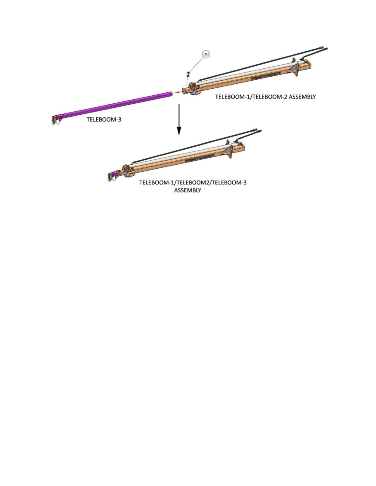
2. PUTTING TOGETHER TELEBOOM ASSEMBLY
•Place TELEBOOM-1/TELEBOOM-2 Assembly on a table. Insert TELEBOOM-3 (32) into
TELEBOOM-2 (24).
•Align holes of TELEBOOM-2 (24) to the farthest holes of TELEBOOM-3 (32) and insert LOCK
PIN (29) through these holes to lock the TELEBOOM Assembly together.
7
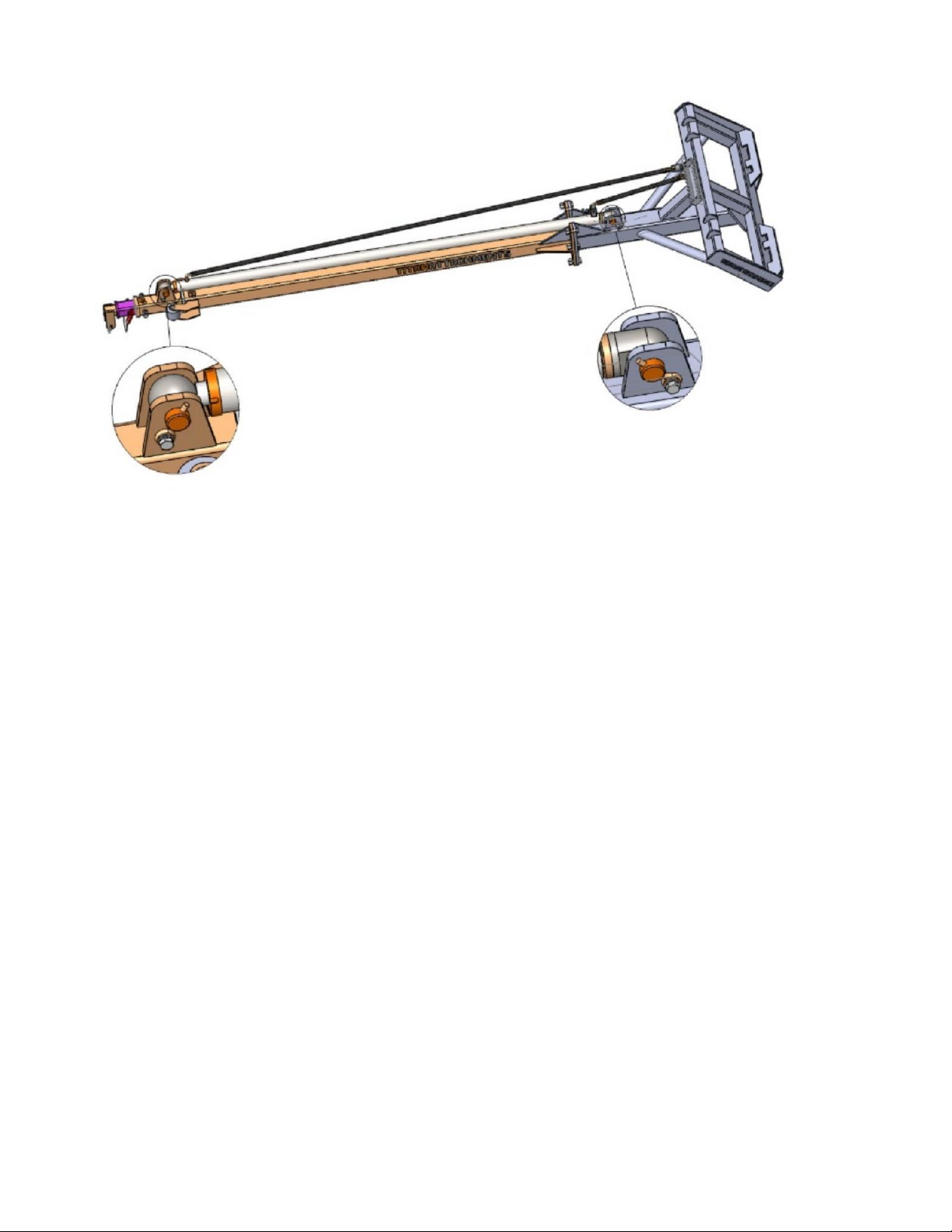
3. ATTACHING MAIN FRAME TO THE TELEBOOM ASSEMBLY
•Move skid steer loader that picks up the MAIN FRAME (10) to the table where the TELEBOOM
Assembly is placed.
•The hardware sets that are used to mount the Main Frame onto the Teleboom Assembly are
attached to the main frame for transportation. Take off the hardware for use in mounting.
•Tilt the MAIN FRAME (10) to vertical position and move the MAIN FRAME (10) towards the
Teleboom Assembly and insert the tube of TELEBOOM-2 (24) into the MAIN FRAME (10).
•Align the bolt holes of the mounting brackets on the MAIN FRAME (10) and TELEBOOM-2 (24)
and attach the MAIN FRAME (10) and TELEBOOM-2 (24) using HEX BOLT M20x60 (11), FLAT
WASHER M20 (12), SPRING WASHER M20 (13) and HEX NUT M20 (14). The order of assembly
is to insert HEX BOLT M20x60 (11) through these parts, and then place FLAT WASHER M20
(12), SPRING WASHER M20 (13) and HEX NUT M20 (14) onto the end of the bolt.
•Fasten the hardware, but do not tighten until all the hardware is attached.
TORQUE REQUIREMENT OF TIGHTENING THE M20 HARDWARE SET IS 363 NM (268 FT-LB).
8
4. MOUNTING CYLINDER
•Align holes of CYLINDER (31) with the mount tabs on MAIN FRAME (10) and insert CYLINDER
PIN (27) Into these holes.
•Insert EYE PIN (6) into the holes of CYLINDER PIN (27) and secure the EYE PIN (6) onto MAIN
FRAME (10) using HEX BOLT M12x30 (9), FLAT WASHER M12 (7) and SPRING WASHER M12
(8). The order of assembly is to place FLAT WASHER M12 (7) and SPRING WASHER M12 (8)
onto the end of the bolt that is inserted through the eye of the EYE PIN (6), and then fasten
HEX BOLT M12x30 (9) onto the threaded hole on the MAIN FRAME (10).
•TORQUE REQUIREMENT OF TIGHTENING THE M12 HARDWARE SET IS 86 NM (64 FT-LB).
•Hook up hydraulic hoses and the TRUSSBOOM is ready for use.

9
HYDRAULIC SYSTEM
SAFETY VALVE
•Titan TRUSSBOOM is equipped with safety valve that
serves to regulate hydraulic oil flows so that in the event
of hydraulic failure, the boom will not collapse instantly
causing hazard.
•Speed of cylinder retraction is adjustable. Turning control
knob clockwise will reduce flow and slow down retraction
speed. Turning control knob anticlockwise will increase
flow and speed up retraction speed.
•Slow retraction speed is recommended.
•Hydraulic pressure range of the safety valve is 2320 to
3625 PSI.
KEY
DESCRIPTION
QTY
(31)
HYDRAULIC CYLINDER
1
(1)
SAFETY VALVE
1
(35)
GASKET Ø3/8”
1
(34)
HOSE CONNECTOR G3/8”
1
(2)
OIL HOSE - FEED
1
(3)
FLAT FACE COUPLER - MALE
1
(4)
FLAT FACE COUPLER -FEMALE
1
(33)
OIL HOSE - RETURN
1
10
ACKNOWLEDGEMENT OF RISK AND RELEASE OF LIABILITY
The use of any equipment, including this one, involves the potential risk of injury. Apart from any
warranty claim that might be presented for a claimed defect in material or workmanship of the product,
you accept and assume full responsibility for any and all injuries, damages (both economic and non-
economic), and losses of any type, which may occur, and you fully and forever release and discharge
Titan, its insurers, employees, officers, directors, associates, and agents from any and all claims,
demands, damages, rights of action, or causes of action, present or future, whether the same be known
or unknown, anticipated, or unanticipated, resulting from or arising out of the use of said equipment.
This equipment must be used with care by capable and competent individuals under supervision, if
necessary.
WARNING
Do not overfill! Mower should be level
when checking oil in gear box.
some activities might be able to cause
electric shock
Sharp objects may be involved.
Use protective cover during maintenance.
TITAN LIMITED WARRANTY: TERMS, EXCLUSIONS AND LIMITATIONS OF REMEDIES
This product comes with a one (1) year limited warranty that can be found at
www.palletforks.com/warranty.html. Please review the same for all details regarding the Titan Limited
Warranty.
THE TITAN LIMITED WARRANTY FOUND AT WWW.PALLETFORKS.COM/WARRANTY.HTML IS
EXCLUSIVE AND IS IN LIEU OF ALL OTHER WARRANTIES, EXPRESS OR IMPLIED, INCLUDING ANY
IMPLIED WARRANTY OF MERCHANTABILITY AND/OR FITNESS FOR A PARTICULAR PURPOSE, EACH
OF WHICH IS HEREBY DISCLAIMED.

11
NEED HELP? CONTACT US FIRST.
1-800-605-7595
www.palletforks.com
© 2023 Titan Brands
This manual suits for next models
2
Table of contents
Other Titan Attachments Industrial Equipment manuals


