Titan Electronics PCIe-400i User manual

PCI Express 4-Port Industrial Serial I/O Cards
The PCIe-400i and PCIe-400i-SI PCI Express 4-port industrial serial I/O cards are plug & play
high-speed serial I/O expansion cards for the PCI Express bus. Connecting to a PCI Express
bus on your computer, the PCI Express 4-port industrial serial I/O card instantly adds four
RS-422/485 serial I/O communication ports to your system. The PCI Express 4-port industrial
serial I/O cards are designed to utilize the Exar XR17V354 PCI Express to UART chip. The
PCIe-400i & PCIe-400i-SI support high-speed data rate up to 921.6 Kbps. Each serial port is
fully compatible with 16C550 UART, with enhanced feature of 256 bytes TX and RX FIFO
buffer for higher performance.
The PCI Express 4-port serial I/O card is an advanced and high efficient solution for serial
data communication and industrial automation applications.
Features of PCI Express 4-Port Industrial Serial I/O Cards
PCI Express 2.0 Gen 1 compliant
PCI Express 1 Lane compliant
16C550 compatibility
256 bytes receive FIFO buffer
256 bytes transmit FIFO buffer for high speed data throughput
Automatic RTS/CTS or DTR/DSR hardware flow control with programmable
hysteresis
Automatic Xon/Xoff software flow control
Drivers provided for Windows and Linux O.S
Wide ambient temperature operation 0°C to 60°C (32°F to 140°F)
CE, FCC approval
PCIe-400i - Supports four RS-422/485 serial I/O ports
Supports four high speed RS-422/485 serial ports with data transfer rate up to 912.6
Kbps
Provides 15KV ESD protection and 600W surge protection for all serial signals
One DB-37 female connector on board
Provides one DB-37 to four male DB-9 cable. Cable length: 30 cm
RS-422 data signals: TxD-, TxD+, RxD+, RxD- , GND, RTS-, RTS+, CTS+, CTS-
RS-485 data signals: TxD-, TxD+, RxD+, RxD- (4 wire) and data-, data+ (2 wire)
PCIe-400i-SI - Supports Four RS-422/485 serial I/O ports with isolation and surge
protection
Supports four high speed RS-422/485 serial ports with data transfer rate up to 912.6
Kbps
Provides 15KV ESD protection and 600W surge protection for all serial signals
Provides 3000 Volt DC optical isolation for all serial signals
One DB-37 female connector on board
Provides one DB-37 to four male DB-9 cable. Cable length: 30CM
RS-422 data signals: TxD-, TxD+, RxD+, RxD- , GND, RTS-, RTS+, CTS+, CTS-
RS-485 data signals: TxD-, TxD+, RxD+, RxD- (4 wire) and data-, data+ (2 wire)
PCI Express 4-Port Industrial Serial I/O Card User Guide
1
Specifications
The tables below show the specifications of PCI Express 4-Port Industrial Serial I/O cards
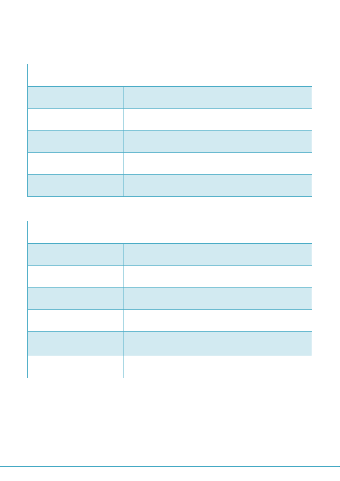
General
Bus
PCI Express; Single-Lane (x1)
Chipset
EXAR XR17V354
Interface
RS-422/485
Plug & Play
Supported
IRQ &IO Address
Assigned by system BIOS
Serial Port
Serial Ports Number
4-Port
RS-422 Signals
TxD-, TxD+, RxD+, RxD-, GND, RTS-, RTS+, CTS+,CTS-
RS-485 Signals
TxD-, TxD+, RxD+, RxD- (4 wire), data- , data+ (2 wire)
Max. Bitrates
921,600 bps
Serial Configuration
Data bits : 5,6,7,8
Parity : None, Odd, Even, Mark , Space
Stop bits : 1, 1.5 , 2
UART FIFO Buffer size
Each port with 256 Bytes FIFO for transmit and receive
PCI Express 4-Port Industrial Serial I/O Card User Guide
2
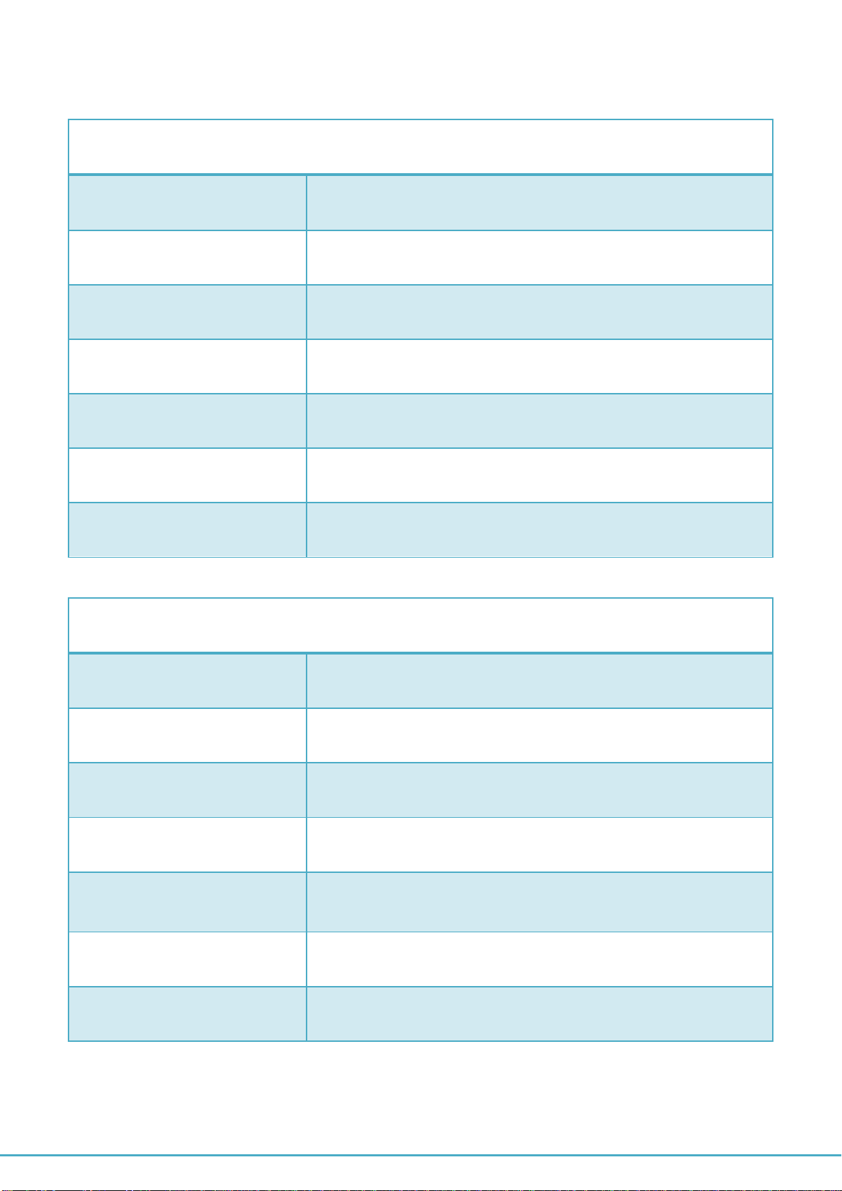
Specification of PCIe-400i and PCIe-400i-SI
PCIe-400i
Serial Ports
4-Port RS-422/485
RS-422 Signals
TxD-, TxD+, RxD+, RxD-, GND, RTS-, RTS+, CTS+,CTS-
RS-485 Signals
TxD-, TxD+, RxD+, RxD- (4 wire), data- , data+ (2 wire)
Connectors
One DB-37 female connector
Protection
15KV ESD protection and 600W surge protection for all serial
signals
Mechanical
PCIe-400i with standard height bracket
Chipset
EXAR XR17V354 PCI Express to quad UART chip
PCIe-400i-SI
Serial Ports
4-Port RS-422/485
RS-422 Signals
TxD-, TxD+, RxD+, RxD-, GND, RTS-, RTS+, CTS+,CTS-
RS-485 Signals
TxD-, TxD+, RxD+, RxD- (4 wire), data- , data+ (2 wire)
Connectors
one DB-37 female connector
Protection
15KV ESD protection for all serial signals
600W surge protection for all serial signals
3000 Volt DC optical isolation for all serial signals
Mechanical
PCIe-400i-SI with standard bracket
Chipset
EXAR XR17V354 PCI Express to quad UART chip

PCI Express 4-Port Industrial Serial I/O Card User Guide
3
Environment
Operating Temperature
0°C to 60°C
Storage Temperature
-40°C to 85°C
Humidity
0 to 80% RH. Noncondensing
Safety Approvals
CE, FCC
PCI Express 4-Port Industrial Serial I/O Card User Guide
4
Pin-out Information
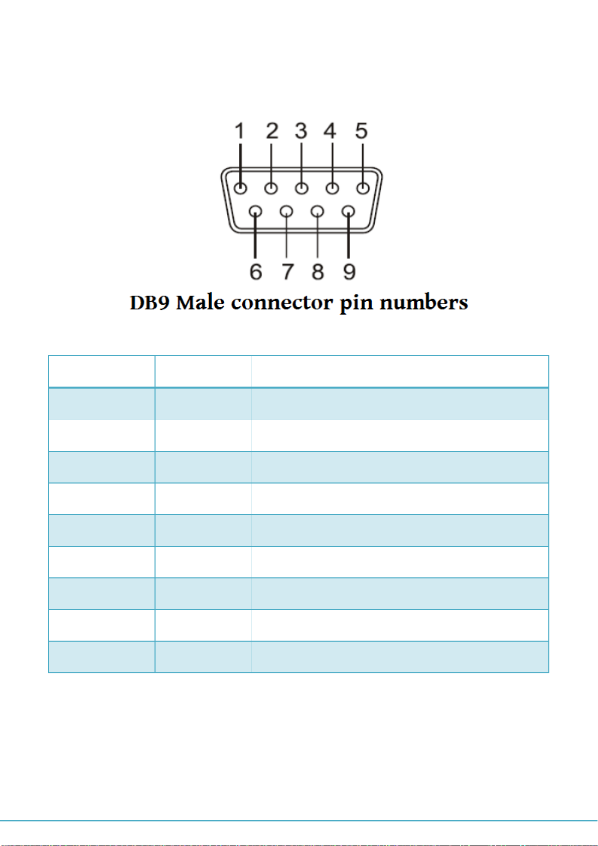
Followings are the pin-out of DB-9 connector of DB-37 to quad male DB-9 cable
RS-422 Pin-out for DB-9 connector
Pin Number
Pin Type
Description
1
Output
TxD- : Transmit Data , negative polarity
2
Output
TxD+ : Transmit Data , positive polarity
3
Input
RxD+ : Receive Data , positive polarity
4
Input
RxD- : Receive Data , negative polarity
5
Ground
GND : Signal Ground
6
Output
RTS- : Request To Send, negative polarity
7
Output
RTS+ : Request To Send, positive polarity
8
Input
CTS+ : Clear To Send, positive polarity
9
Input
CTS- : Clear To Send, negative polarity

PCI Express 4-Port Industrial Serial I/O Card User Guide
5
RS-485 full duplex (4 wire) pin-out for DB-9 connector
Pin Number
Pin Type
Description
1
Output
TxD- : Transmit Data , negative polarity
2
Output
TxD+ : Transmit Data , positive polarity
3
Input
RxD+ : Receive Data , positive polarity
4
Input
RxD- : Receive Data , negative polarity
5
Ground
GND : Signal Ground
RS-485 half duplex (2 wire) pin-out for DB-9 connector
Pin Number
Pin Type
Description
1
Out/In
Data- : Transmit /Receive Data , negative polarity
2
Out/In
Data+ : Transmit /Receive Data , positive polarity
5
Ground
GND : Signal Ground
PCI Express 4-Port Industrial Serial I/O Card User Guide
6
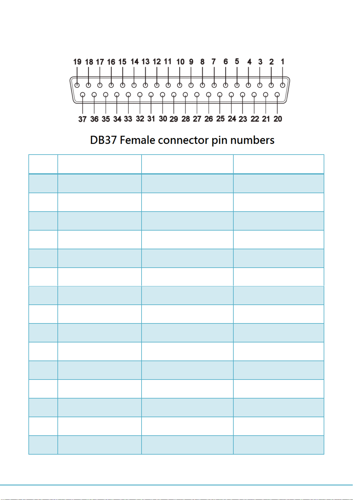
Pin-out of one DB-37 female connector for four RS-422/485 ports
Pin
RS-422 Mode
RS-485 “4W” Mode
RS-485 “2W” Mode
1
.NC.
.
2
TxD-(3)
TxD-(3)
Data-(3)
3
Ground
Ground
Ground
4
CTS+(3)
5
TxD+(3)
TxD+(3)
Data+(3)
6
CTS-(4)
7
RxD-(4)
RxD-(4)
8
RTS-(4)
9
RTS+(4)
10
RxD+(4)
RxD+(4)
11
TxD-(2)
TxD-(2)
Data-(2)
12
Ground
Ground
Ground
13
CTS+(2)
14
TxD+(2)
TxD+(2)
Data+(2)
15
CTS-(1)
PCI Express 4-Port Industrial Serial I/O Card User Guide
7
16
RxD-(1)
RxD-(1)
17
RTS-(1)
18
RTS+(1)
19
RxD+(1)
RxD+(1)
20
CTS-(3)
21
RxD-(3)
RxD-(3)
22
RTS-(3)
23
RTS+(3)
24
RxD+(3)
RxD+(3)
25
TxD-(4)
TxD-(4)
Data-(4)
26
Ground
Ground
Ground
27
CTS+(4)
28
TxD+(4)
TxD+(4)
Data+(4)
29
CTS-(2)
30
RxD-(2)
RxD-(2)
31
RTS-(2)
32
RTS+(2)
33
RxD+(2)
RxD+(2)
34
TxD-(1)
TxD-(1)
Data-(1)
35
Ground
Ground
Ground
36
CTS-(1)
37
TxD+(1)
TxD+(1)
Data+(1)

PCI Express 4-Port Industrial Serial I/O Card User Guide
8
Installation
Windows 7/ 8/ 8.1 32-bit & 64-bit Drivers Installation
To install theWindows driver from Device Manager for PCI Express 4-port industrial serial I/O
card, please follow the steps below:
1. Switch off the computer.
2. Insert PCI Express industrial serial I/O card into a free PCI Express Bus slot.
3. Switch on the computer and start Windows O.S.
4. Windows O.S will automatically detect the PCI Express I/O Card.
5. Press “START” button and select “Control Panel”.
PCI Express 4-Port Industrial Serial I/O Card User Guide
9
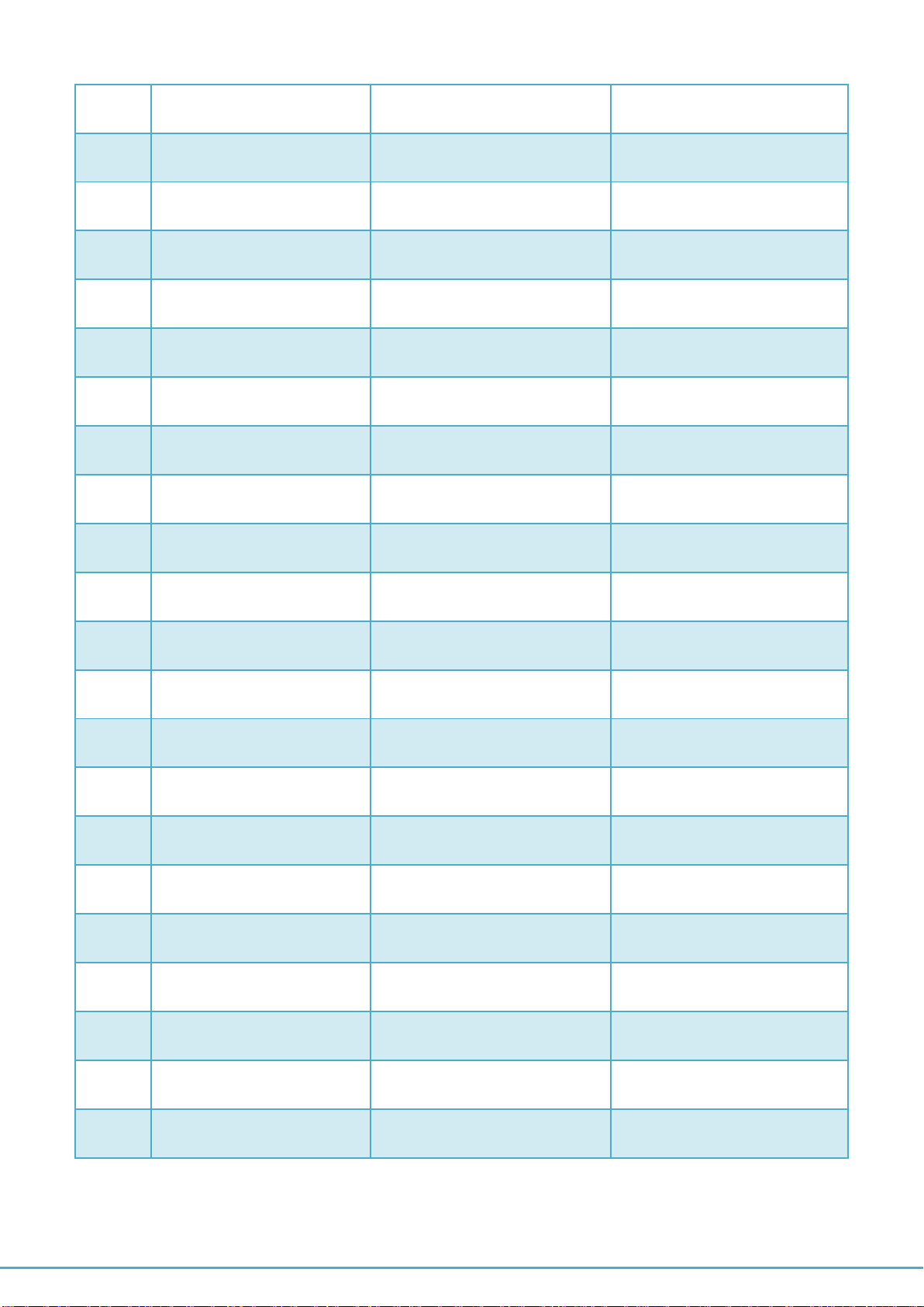
6. Select “Hardware and Sound”.
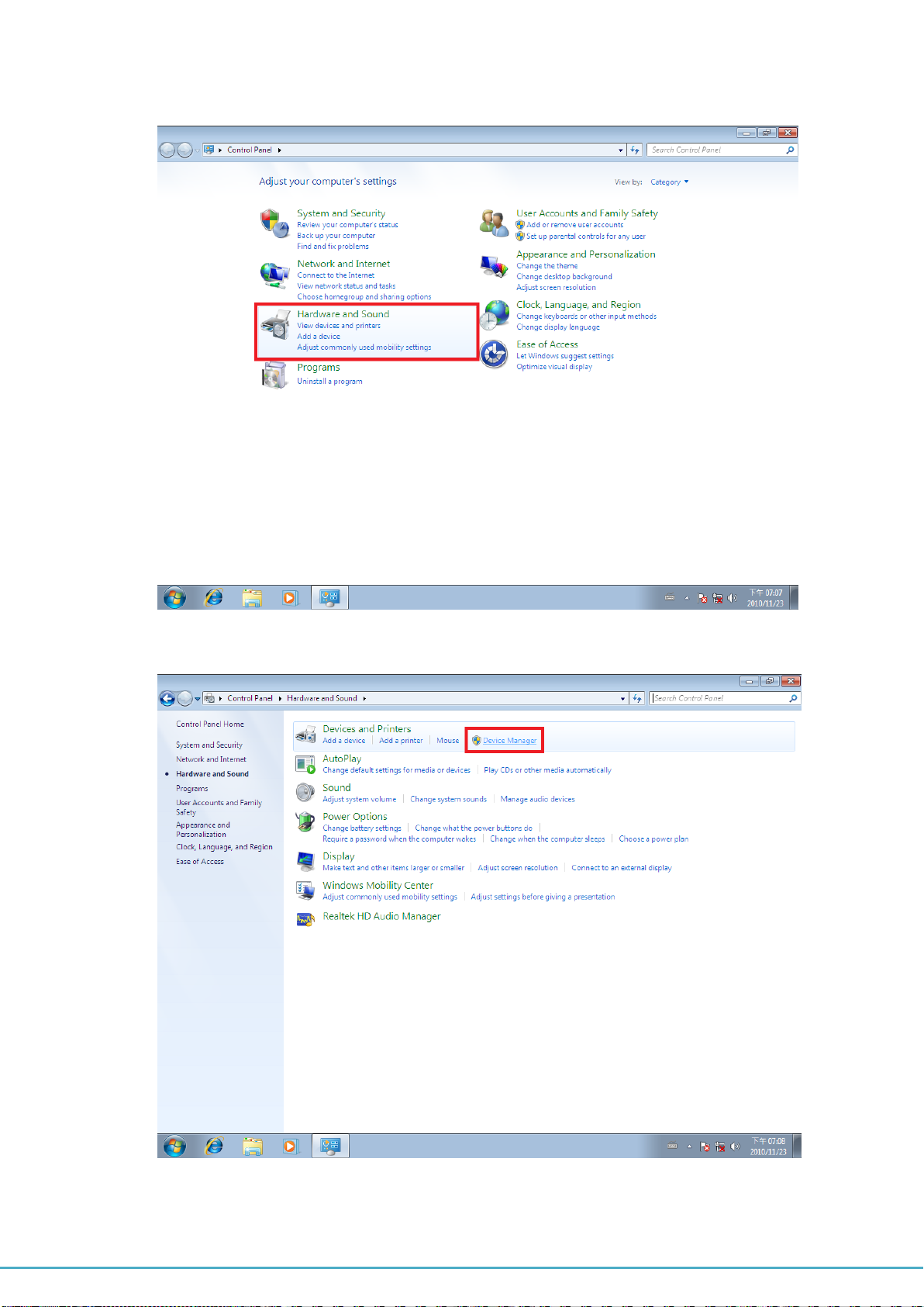
7. Select “Device Manager”.

PCI Express 4-Port Industrial Serial I/O Card User Guide
10
8. Under “Device Manager” of the System properties, you can find “PCI Serial Port”
attached to “Other devices”. Select “PCI Serial Port”.
9. Select “Action” and execute “Update Driver Software”.
PCI Express 4-Port Industrial Serial I/O Card User Guide
11
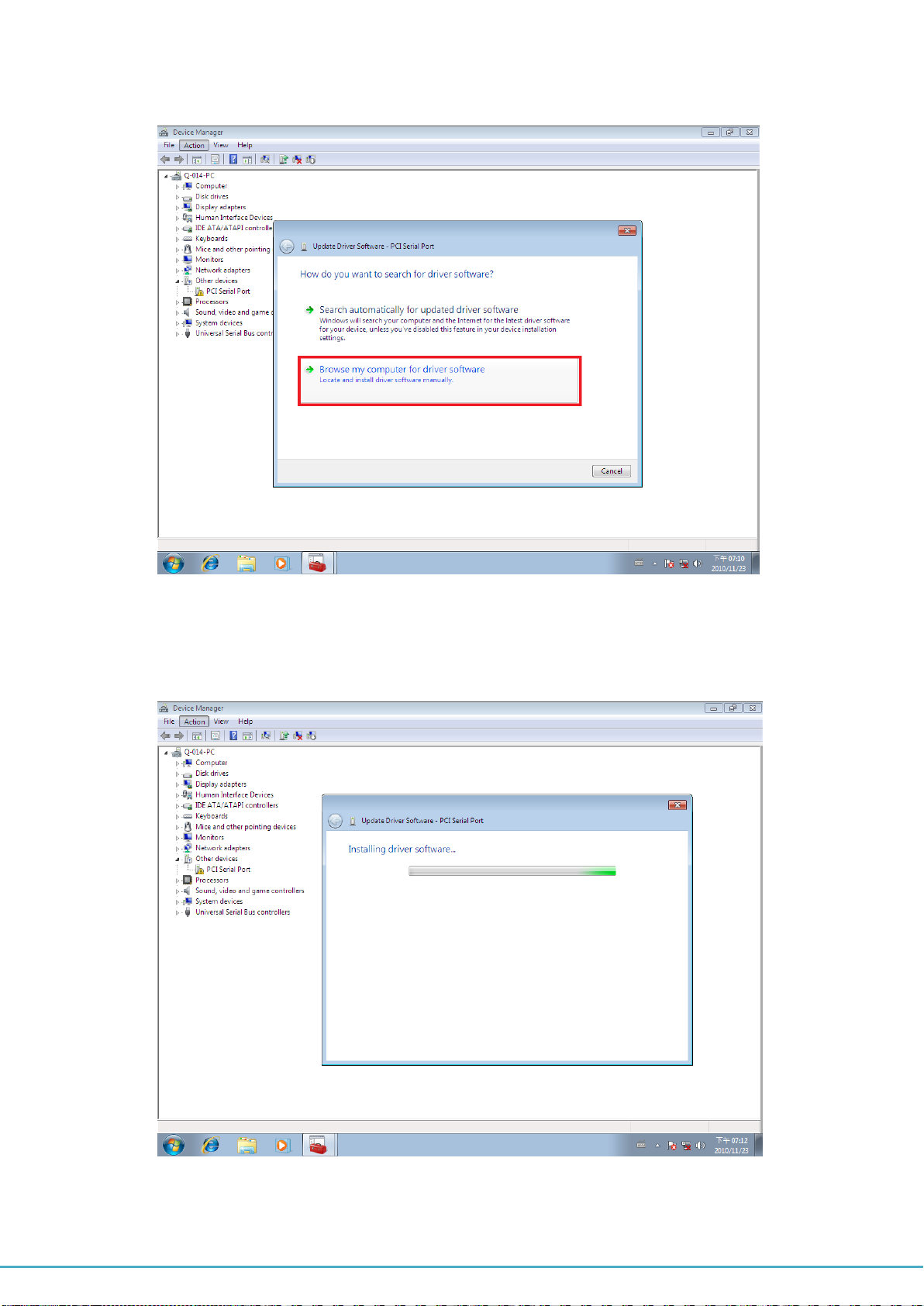
10. Click “Browse my computer for driver software”.
11. Insert the driver CD into the CD-ROM or DVD-ROM drive.
12. Select the directory "\PCIe Drivers\x86” for 32 bits Windows O.S (“\PCIe Drivers\x64
for 64 bits Windows O.S”) as the target. Click on "OK", and on “Next” to install driver.
PCI Express 4-Port Industrial Serial I/O Card User Guide
12
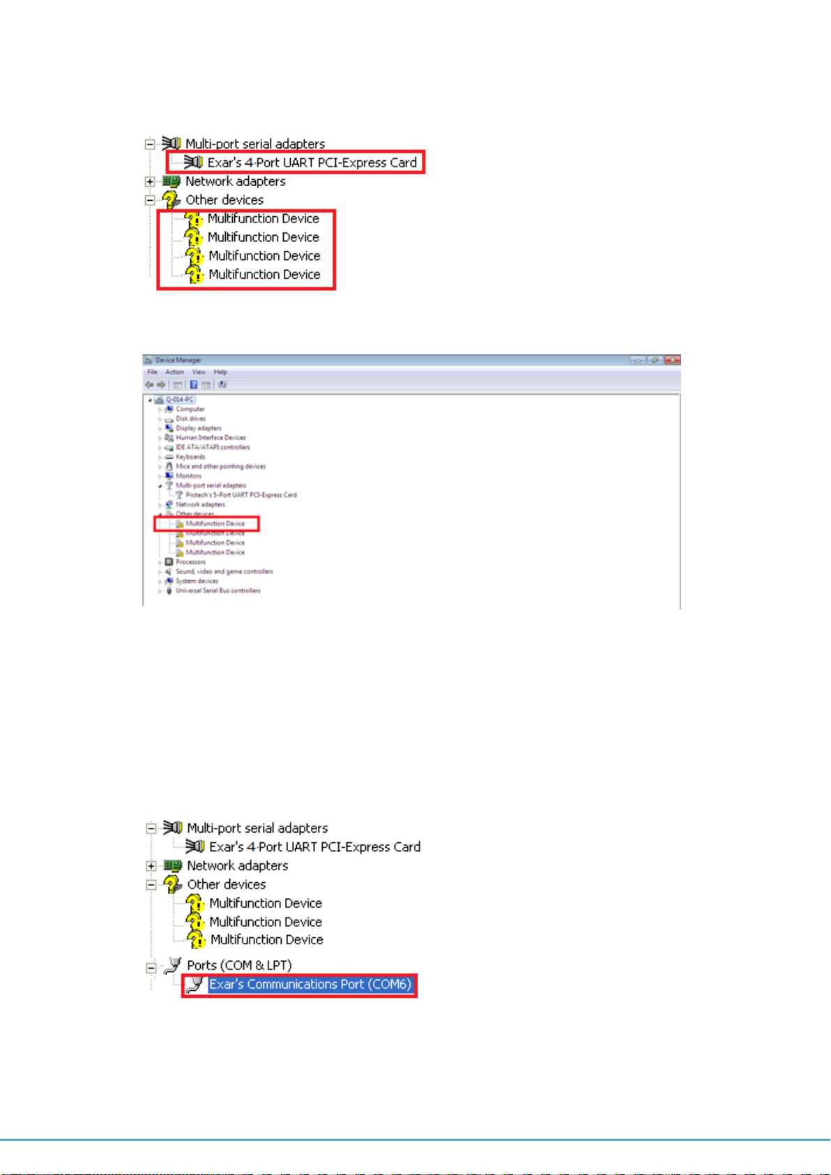
13. After driver installation is done successfully, you can find “Exar’s 4-Port UART
PCI-Express Card” and four “Multifunction Device” under Device Manager.
14. Select first “Multifunction Device”.
15. Select “Action” and execute “Update Driver Software”.
16. Click “Browse my computer for driver software” again.
17. Select the directory "\PCIe Drivers\x86” for 32 bits Windows O.S (“\PCIe Drivers\x64
for 64 bits Windows O.S”) as the target. Click on "OK", and on “Next” to install COM
port driver.
18. After COM port driver installation is done successfully, you can find first “Exar’s
Communications Port (COMx)” under “Ports (COM & LPT)”in Device Manager.
19. Select next “Multifunction Device”by order and repeat step 15~17 to install COM
port driver for all “Multifunction Device”.

PCI Express 4-Port Industrial Serial I/O Card User Guide
13
20. After all COM port driver installation is done successfully, you can find four “Exar’s
Communications Port (COMx)” under “Ports (COM & LPT)” in Device Manager.
21. Restart computer to complete installation.
PCI Express 4-Port Industrial Serial I/O Card User Guide
14
Hardware Setting and Installation:
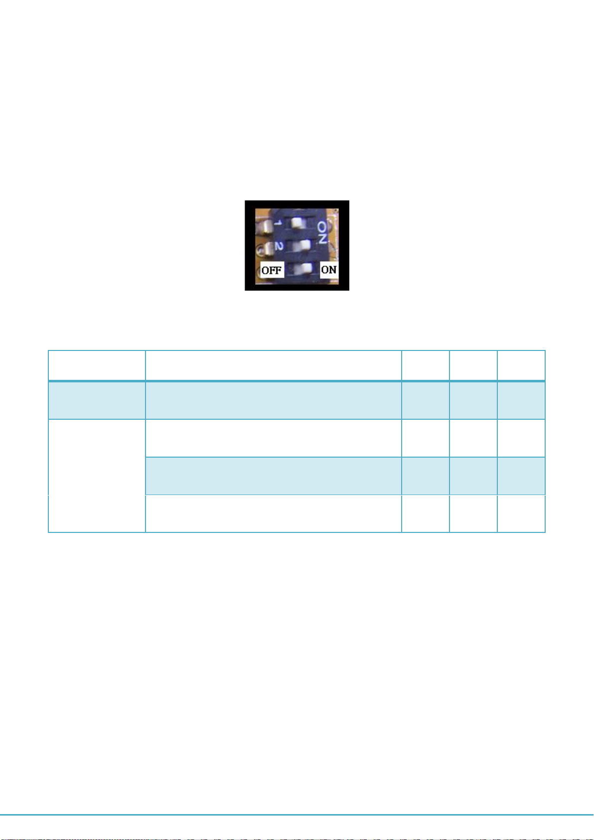
Selecting the RS-422/485 operation mode
There are four 3-pin DIP switches, SW1, SW2, SW3, SW4, on PCIe-400i and PCIe-400i-SI
cards. The DIP switches are set to select the mode of operation. You will need to set the
switch settings to RS-422 mode, or RS-485 mode, as per the requirements of your
application. The RS-422 & RS-485 Mode Block Configuration Settings are listed as follows.
SW1, SW2, SW3, SW4 for Mode Setting
Operation Mode
1
2
3
RS-422
4 wire with Handshaking
ON
ON
ON
RS-485
Full Duplex (4 wire)
OFF
ON
ON
Half Duplex (2 wire) - with Echo
OFF
OFF
ON
Half Duplex (2 wire) - without Echo
OFF
OFF
OFF
When PCIe-400i and PCIe-400i-SI working in RS-485 operation mode, you need to
enable the automatic direction control of the RS-485 transceiver buffer by setting the
driver configured to enable RS-485 function (refer to page 16).

PCI Express 4-Port Industrial Serial I/O Card User Guide
15
There are four 6-pin DIP switches, S1, S2, S3, S4, on PCIe-400i and PCIe-400i-SI cards. The
DIP switches are set to enable TxD, RxD, 120 ohm termination resistors and RxD, TxD 750
Ohm biasing resistors. You will need to set the four 6-pin DIP switches, S1, S2, S3, S4, for
RS-422 mode, or RS-485 mode, as per the requirements of your application. Settings are
listed as follows:
DIP Switch
Function
Remark
S1,2,3,4 pin1
ON
Enable TxD+ biasing resistor
Pull-up TxD+ with 750 ohm resistor
S1,2,3,4 pin2
ON
Enable TxD+/TxD- termination
resistor
120 ohm termination resistor
S1,2,3,4 pin3
ON
Enable TxD- biasing resistor
Pull-down TxD- with 750 ohm
resistor
S1,2,3,4 pin4
ON
Enable RxD+ biasing resistor
Pull-up RxD+ with 750 ohm resistor
S1,2,3,4 pin5
ON
Enable RxD+/RxD- termination
resistor
120 ohm termination resistor
S1,2,3,4 pin6
ON
Enable RxD- biasing resistor
Pull-down RxD- with 750 ohm
resistor

PCI Express 4-Port Industrial Serial I/O Card User Guide
16
Enable RS-485 operation mode for PCIe-400i and PCIe-400i-SI.
When PCIe-400i or PCIe-400i-SI works in RS-485 operation mode, you need to enable the
automatic direction control of the RS-485 transceiver buffer by setting the driver configured to
enable RS-485 function.
1. Double click on “Exar’s Communications Port (COMx)” under Device Manager into
“Exar’s Communications Port (COMx) Properties”. Check the “RS-485” to enable the
automatic direction control of the RS-485 transceiver buffer in the RS-485 operation
mode.
2. Click on “OK” under “Exar’s Communications Port (COMx) Properties” to enable the
automatic direction control of the RS-485 transceiver buffer for RS-485 mode operation.
3. Repeat step 1 to 2 for other COM port to enable the automatic direction control of RS-485
mode operation.
Proper Wiring for RS-422/485 Operation
This section will provide proper wiring information about RS-422 and RS-485 data
communication. It is necessary to have the basic knowledge, to avoid or find errors in data
transmission. Failures in cabling are responsible for the vast majority of transmission
problems.

PCI Express 4-Port Industrial Serial I/O Card User Guide
17
RS-422 and RS-485 Transmission Technique
The RS-422 and RS-485 use the same balanced transmission method. Signals are not
transmitted as voltage on a single wire, as RS-232 does. Instead two wires are used; when
one carries high voltage, the other one carries low voltage. The signal is defined by the
difference in voltage between those two wires. This hardens the transmission against noise.
Usually twisted pair cables are used, which further reduces the sensitivity for noise.
To make sure the signals meet the common voltage range, the GND of sender and receiver
must be connected somehow. To insure the signals are in the valid voltage range and the
differential voltage can be correctly sensed by the receiver, the GND lines of the transmitter
and receiver must be connected.
RS-422 without handshaking signals connected
The following diagram shows RS-422 without handshaking signals connected.
PCI Express 4-Port Industrial Serial I/O Card User Guide
18
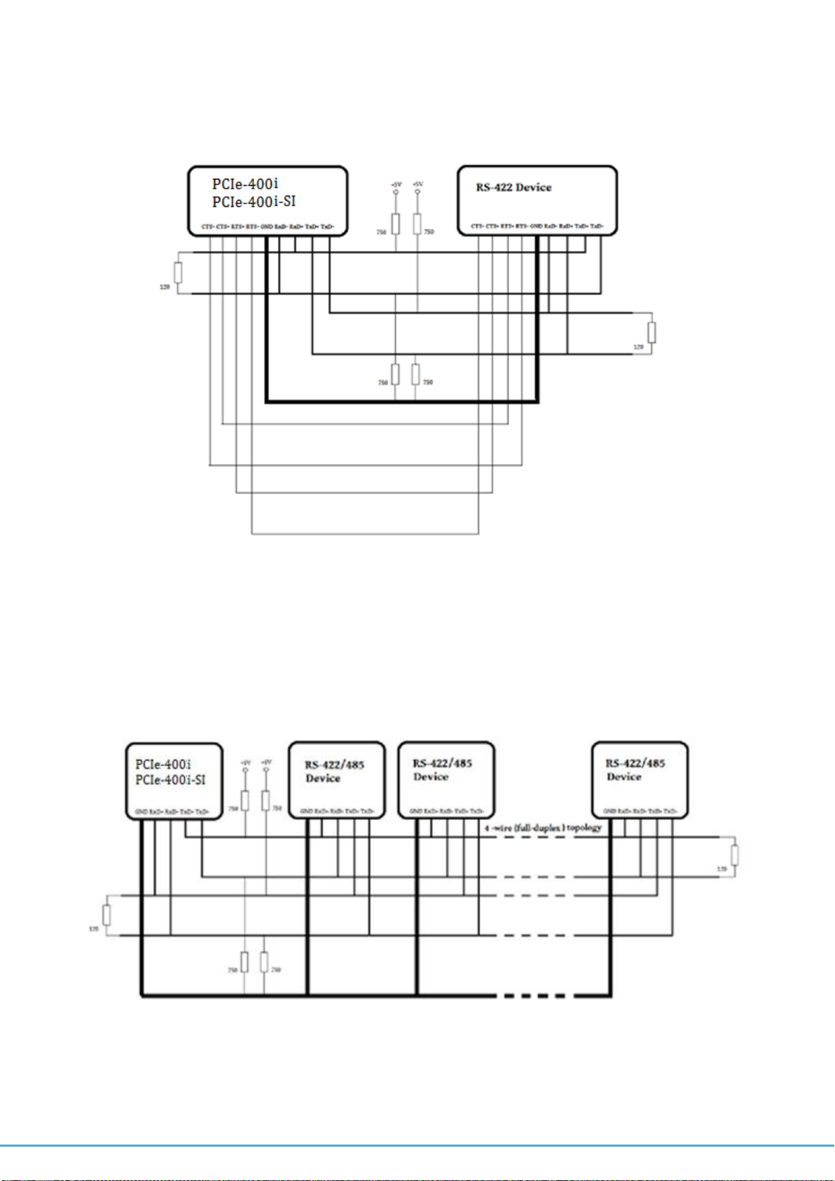
RS-422 with handshaking signals connected
The following diagram shows RS-422 with handshaking signals connected.
RS-422 and RS-485 4-Wire Scheme
The RS-422 requires dedicated wire pairs for transmit and receive. The transmit wires are
used to send data to as many as 10 receivers, as stated in the specifications of RS-422.
Since the PCIe-400i and PCIe-400i-SI use RS-485 line driver technology, up to 32 receivers
are possible. The following diagram shows RS-422 and RS-485 4-wire scheme:

PCI Express 4-Port Industrial Serial I/O Card User Guide
19
The following diagram shows RS-485 2-Wire scheme:
This manual suits for next models
1
Table of contents
Other Titan Electronics PCI Card manuals


