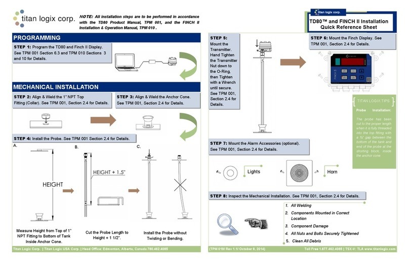
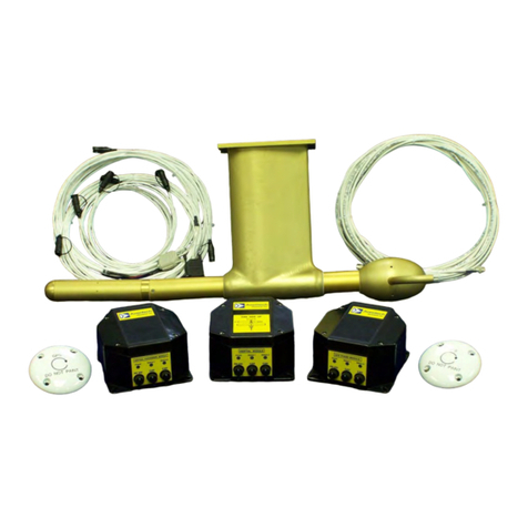
Titan Logix Corp TD100 User manual

TD100 INSTALLATION &
OPERATION MANUAL
TPM 057
Version 1.0

TPM 057 Version 1.0, May 31, 2018 i
CONTENTS
TABLE OF FIGURES ................................................................................................................ iii
1 CUSTOMER SUPPORT ...................................................................................................... 1
1.1 Returns for Re air, Re lacement, or Credit .................................................................................... 1
2 INTRODUCTION .............................................................................................................. 2
2.1 Warranty .......................................................................................................................................... 2
2.2 Disclaimer ........................................................................................................................................ 2
2.3 Pro rietary Information ................................................................................................................... 2
2.4 Safety ............................................................................................................................................... 2
3 SYSTEM OVERVIEW ........................................................................................................ 4
3.1 Com onents ..................................................................................................................................... 5
3.1.1 O tional Com onents ............................................................................................................. 6
3.2 System S ecifications ....................................................................................................................... 7
3.3 Transmitter Shear Point ................................................................................................................... 8
3.4 Probe Sensing................................................................................................................................... 8
3.4.1 Deadband Areas ...................................................................................................................... 8
3.4.2 Band Clear ............................................................................................................................. 10
3.4.3 Smart Sensing ........................................................................................................................ 11
3.5 Alarm Points ................................................................................................................................... 11
3.5.1 Finch II Generated Alarms ..................................................................................................... 12
3.5.2 5332INT Generated Alarms ................................................................................................... 13
3.6 Finch II Dis lay ............................................................................................................................... 14
3.6.1 Finch II Interface .................................................................................................................... 14
3.6.2 Finch II Modes of O eration .................................................................................................. 17
3.6.3 Finch II Relays ........................................................................................................................ 19
3.7 5332 INT In-Cab Dis lay ................................................................................................................. 20
3.7.1 5332INT In-Cab Interface ...................................................................................................... 20
3.7.2 5332INT In-Cab Modes of O eration .................................................................................... 22
4 INSTALLATION .............................................................................................................. 25
4.1 Pre-Installation ............................................................................................................................... 25
4.1.1 Installation Equi ment .......................................................................................................... 25
4.2 Mechanical Installation .................................................................................................................. 25
4.2.1 Probe Installation .................................................................................................................. 27

TPM 057 Version 1.0, May 31, 2018 ii
4.2.2 Transmitter Installation ......................................................................................................... 34
4.2.3 Finch II/5332INT Dis lay Installation .................................................................................... 35
4.2.4 Accessories Installation (O tional) ........................................................................................ 35
4.3 Electrical Installation ...................................................................................................................... 35
4.3.1 Installation Wiring – System ................................................................................................. 36
4.3.2 Installation Wiring - Transmitter .......................................................................................... 37
4.3.3 Installation Wiring - Finch II Relays ....................................................................................... 38
4.3.4 Installation Wiring – 5332INT In-Cab Dis lay ........................................................................ 39
4.3.5 Installation Wiring - Current Loo O tion ............................................................................. 40
5 CONFIGURATION & CALIBRATION ................................................................................. 42
5.1 Transmitter .................................................................................................................................... 42
5.2 Finch II Dis lay ............................................................................................................................... 43
5.3 Current Loo Transmitter (O tion) ................................................................................................ 43
5.4 Start U .......................................................................................................................................... 44
5.5 Offset Calibration ........................................................................................................................... 46
5.5.1 Method 1: Offset Calibration Using a Loaded and Metered Volume ................................... 46
5.5.2 Method 2: Offset Calibration Using an Unloaded and Metered Volume ............................. 46
5.5.3 Method 3: Offset Calibration Using a Measured Level ......................................................... 47
5.6 S ill Alarm Reset ............................................................................................................................ 47
5.6.1 Offset Calibration Method .................................................................................................... 47
6 TROUBLES OOTING & MAINTENANCE .......................................................................... 49
6.1 Required Tools and Equi ment...................................................................................................... 49
6.2 Error Codes .................................................................................................................................... 49
6.3 System Troubleshooting ................................................................................................................ 52
6.4 Current Loo System (O tion) ....................................................................................................... 56
6.5 Re air ............................................................................................................................................. 57
6.6 Maintenance .................................................................................................................................. 57
7 REFERENCE DRAWINGS ................................................................................................. 58

TPM 057 Version 1.0, May 31, 2018 iii
TABLE OF FIGURES
Figure 1 TD 100 System ................................................................................................................................. 4
Figure 2 TD100 Transmitter .......................................................................................................................... 5
Figure 3 TD100 Probe.................................................................................................................................... 5
Figure 4 Finch II Dis lay ................................................................................................................................ 6
Figure 5 5332INT In-Cab Dis lay ................................................................................................................... 6
Figure 6 Gateway Transmitter ...................................................................................................................... 6
Figure 7 MIC 10 Interface.............................................................................................................................. 6
Figure 8 Rack Control Module ...................................................................................................................... 6
Figure 9 Air-Weigh Scale ............................................................................................................................... 7
Figure 10 Transmitter Head Shear Point ....................................................................................................... 8
Figure 11 Deadband Areas ............................................................................................................................ 9
Figure 12 Band-Clear Region ....................................................................................................................... 10
Figure 13 Alarm Points ................................................................................................................................ 11
Figure 14 Fill/Fall Alarm Region .................................................................................................................. 11
Figure 15 Finch II Dis lay ............................................................................................................................ 15
Figure 16 Finch II Relay Assignments .......................................................................................................... 19
Figure 17 5332INT In-Cab Dis lay ............................................................................................................... 21
Figure 18 5332INT Off Mode ...................................................................................................................... 22
Figure 19 5332INT Fill/Fall Dis lay .............................................................................................................. 22
Figure 20 2 Lo Dis lay ................................................................................................................................. 23
Figure 21 Offset Calibration Dis lay ........................................................................................................... 23
Figure 22 TD100 System Mount - Side View ............................................................................................... 26
Figure 23 TD100 System Mount - To View ............................................................................................... 27
Figure 24 Probe Location ............................................................................................................................ 28
Figure 25 Curved Surface Fitting Mount ..................................................................................................... 29
Figure 26 To Fitting Location .................................................................................................................... 30
Figure 27 Anchor Cone Location ................................................................................................................. 31
Figure 28 Probe Measurement ................................................................................................................... 33
Figure 29 Cutting the Probe ........................................................................................................................ 33
Figure 30 Probe Installation ........................................................................................................................ 34
Figure 31 Basic System Wiring Diagram ..................................................................................................... 36
Figure 32 Transmitter/Finch II Connections Schematic .............................................................................. 37
Figure 33 5332INT In-Cab Wiring Diagram ................................................................................................. 39
Figure 34 Current Loo Wiring Diagram ..................................................................................................... 41
Figure 35 TD100 Transmitter Wiring Schematic ......................................................................................... 41
Figure 36 SensorLink
TM
Stra ing Table ..................................................................................................... 42
Figure 37 SensorLink
TM
4-20mA Set Points ................................................................................................. 43
Figure 38 TD100 System Com onent Location ........................................................................................... 58

TPM 057 Version 1.0, May 31, 2018 Page | 1
CUSTOMER SUPPORT
TD100 Installation and O eration Manual
1CUSTOMER SUPPORT
24 our Technical Support Line
1-877-462-4085
Titan Logix rovides 24-hour technical su ort for their roducts. Call the technical su ort number:
•to arrange a service call
•if you have immediate questions regarding o erations and installation
•if you have a request for documentation and/or software
•technical assistance
1.1 R
ETURNS FOR
R
EPAIR
,
R
EPLACEMENT
,
OR
C
REDIT
Inside Sales
Inside SalesInside Sales
Inside Sales
(8:00
(8:00(8:00
(8:00-
--
-4:30 Mountain
4:30 Mountain 4:30 Mountain
4:30 Mountain Daylight Time)
Daylight Time)Daylight Time)
Daylight Time)
1-877-462-4085
NOTE
Returned product for repair, replacement, or credit, must be accompanied by a Titan
Logix generated RMA number.
To obtain an RMA number:
1. Call the Inside Sales number to s eak with a re resentative and obtain an RMA number
2. Provide the serial number of the item with a descri tion of issue and ex ected resolution
(re air, re lacement, return)
3. Describe the issue and indicate whether the item is defective, missing com onents, not suitable
for the intended use, or urchased in error
4. Return the item together with the RMA number to the indicated Titan Logix service facility
When speaking with your Titan Logix representative, please indicate whether the item is still under
warranty.
Shi ing cost to and from a Titan Logix service facility is the res onsibility of the customer unless the
roduct is under warranty. If the roduct is under warranty, the freight cost to Titan Logix is incurred by
the customer. From Titan Logix, the cost is incurred by Titan Logix.
All returns for credit are subject to a restocking fee.

TPM 057 Version 1.0, May 30, 2018 Page | 2
INTRODUCTION
TD100
Installation and
O eration
Manual
2INTRODUCTION
This manual rovides information s ecific to the Titan Logix Cor . TD100
TM
Level Gauge and Overfill
Prevention System (hereafter referred to as the TD100) only.
Installation and o erational information ertaining to o tional equi ment or eri heral systems will not
be included in this manual. Refer to the vendor su lied documents for more information or go to
www.su ort.titanlogix.com for Titan Logix online documents.
This guide is intended to assist the user on the installation, use, and maintenance, of the Titan Logix
TD100, under normal working conditions. Any user erforming installations or o erations outside the
sco e of this guide, are advised to contact Titan Logix technical su ort.
It is essential that this manual be read and understood for ro er installation and o eration of your new
TD100 system.
2.1 W
ARRANTY
Please see the Terms and Conditions at htt ://www.titanlogix.com/ roducts.as x for details about
roduct warranty.
2.2 D
ISCLAIMER
The information in this document is subject to change without notice. Titan Logix Cor . makes no
re resentations or warranties with res ect to the contents hereof.
2.3 P
ROPRIETARY
I
NFORMATION
The Information disclosed herein contains ro rietary rights of Titan Logix Cor . Neither this document
nor the information disclosed herein shall be re roduced or transferred to other documents, or used or
disclosed to others for manufacturing ur oses, or for any other ur ose exce t as s ecifically
authorized in writing by Titan Logix Cor .
2.4 S
AFETY
This manual will use the following standard safety terms and conventions to indicate conditions:
WARNING
Indicates a hazardous situation which, if not avoided, could result in death or serious
injury.

TPM 057 Version 1.0, May 30, 2018 Page | 3
INTRODUCTION
TD100
Installation and
O eration
Manual
CAUTION
Indicates a hazardous situation which, if not avoided, could result in moderate injury
and/or property damage.
NOTE
Indicates an important message not related to personal injury or property damage.
The TD100 system must be installed and o erated in accordance with details described in the Titan Logix
manuals, a lication notes, and all other relevant ublications. Only qualified ersonnel familiar with
the installation and o eration of this equi ment should install, adjust, o erate, or service this
equi ment. Failure to observe this warning could result in bodily injury or loss of life.
Do not install or re air the system where flammable gases and/or fumes may be resent.
Observe all federal, state/ rovincial and local safety standards and industry recommended ractices.
Turn vehicle ower off before any installation or maintenance.

TPM 057 Version 1.0, May 31, 2018 Page | 4
OVERVIEW
TD100
Installation a
nd
O eration
Manual
3SYSTEM OVERVIEW
Figure 1 TD 100 System
The TD100 system consists of a TD100 transmitter, dual-rod robe, a Finch II or 5332INT In-Cab dis lay.
The TD100 system continuously measures liquid level in the tank and transmits volume information to a
dis lay. Relays within the dis lays can be rogrammed to indicate S ill, High-High (HH), and system Fail
alarms to external devices such as overfill revention valves, lights, horns and stationary loading
controls. HH is normally the first shutdown level; S ill is a backu level slightly higher on the robe than
HH, while Fail indicates failure of the TD100 system. Activation of any alarm halts loading to revent a
dangerous overfill condition or s ill at the loading facility. In addition, Fall and Fill alarms, managed by
settings stored in the Finch II dis lay, can control relays that indicate a re-set, increasing Fill or
decreasing Fall level to warn of an a roaching fluid level while loading or unloading roduct .
The TD100 transmitter uses Guided Wave RADAR (GWR) to measure the liquid level in a tank. It does not
use any moving arts for level measurement. The TD100 transmits a continuous stream of radio
frequency ulses into the robe. These ulses travel along the robe and art of the ulse energy is
reflected back to the transmitter when encountering the surface of the liquid in a tank. The time delay
between the transmit ulse and reflected ulse is used to calculate the distance from the tank to

TPM 057 Version 1.0, May 31, 2018 Page | 5
OVERVIEW
TD100
Installation a
nd
O eration
Manual
Figure 3 TD100 Probe
mounted transmitter to the liquid level. This distance is then used to determine level of the liquid in the
tank. The calculated level is converted into common volume units and is sent to the Finch II dis lay.
The SensorLink
TM
software interface com iles and dis lays a stra ing table tracking volume
characteristics and allows the user to view and set alarms. The stra ing table is rogrammed before
installation and o eration on the tank.
O tional com onents are installed as required.
3.1 C
OMPONENTS
TD100 Transmitter (T21)
The TD100 transmitter generates and rocesses the radar signals to
determine liquid level in a tank. The TD100 is mounted on the tank to and
connected to the robe, is weather roof and rated for use in hazardous
locations where ex losive fumes may be resent. TD100 transmitter
connects with a robe and su orts level measurement of a wide range of
liquids.
Current Loop Transmitter (T22)
TD100 transmitters are available with an o tional 4-20mA out ut. This o tion
will communicate level information only (no alarms) and must be ordered
when urchasing the TD100 system. It is not u gradable after manufacture of
the transmitter.
Current loo transmitters are used for long distance communication due to
their insensitivity to electrical noise. They are resistant to ower su ly
voltage variations and wiring resistance.
Dual-Rod Probe
The robe guides the GWR ulse and reflection from the surface of the liquid.
The robe is mounted on the tank to and is connected to the bottom of the
transmitter via the to fitting. It is seated in the anchor cone. The TD100
Transmitter is o timized for use with the Dual-Rod robe and is not
com atible with the Coaxial robe.
The robe is available in a Stainless Steel, or in a Hastelloy® o tion for
corrosive environments.
The Dual-Rod probe is available with Titan Logix supplied 1” NPT top fitting
(recommended) and anchor cone.
Figure 2 TD100 Transmitter
Anchor Cone
Top
Fitting

TPM 057 Version 1.0, May 31, 2018 Page | 6
OVERVIEW
TD100
Installation a
nd
O eration
Manual
Figure 4 Finch II Display
Finch II Display
The Finch II Dis lay is an external use, numeric dis lay of volume information,
alarms, and system error codes from the TD100 transmitter. Various alarm
and error conditions are detected by the transmitter and dis lay. These
alarm states control internal relays for alarm annunciation, high level
shutdown, and low-level revention.
The Finch II contains high current relays to directly control a bottom loading
solenoid valve or control of an onboard loading um . A weather- roof
junction box may be required to terminate alarm accessory wiring.
Refer to TPM 010 – Finch II Installation & O eration Manual.
5332INT In-Cab Display
The 5332INT In-Cab dis lay is a numeric dis lay of fluid volume (or level),
alarms, and system error codes from the TD100 transmitter. It is ty ically
mounted in the driver’s cab for convenience.
SensorLink
TM
The SensorLink
TM
software com iles stra ing table information and,
together with in uts from the user, allows the user to set volume alarms and
track volume levels through the TD100 transmitter.
3.1.1 Optional Components
Gateway
The Gateway module transmits osition and motion information of the vehicle
through a cellular connection, as well as gathering and transmitting data from
the TD100 and Finch II com onents.
Refer to TPM 053 – Gateway Installation & O eration Manual.
MIC 10
The MIC 10 is an interface device for connecting multi le TD100s to a third-
arty Gateway or PLC system. Level, alarm and error information from the
TD100s is collected by the MIC 10 and forwarded to the connected device.
Rack Control Module (RCM)
The RCM is an accessory that enables secondary overfill revention when
used with industry standard o tic and thermistor terminal rack controllers.
The TD100 transmitter sends loaded volume, alarm states and detected
errors to the RCM.
Refer to TPM 007 – Rack Control Module Product Manual.
Figure 332INT In-Cab
Display
Figure 6 Gateway Transmitter
Figure 7 MIC 10 Interface
Figure 8 Rack Control Module

TPM 057 Version 1.0, May 31, 2018 Page | 7
OVERVIEW
TD100
Installation a
nd
O eration
Manual
Figure 9 Air-Weigh Scale
Air-Weigh Load-Maxx
The Air-Weigh Load-Maxx rovides over-weight revention alarms and
shutdowns. Combined with the TD100 and Finch II monitors volume and
weight simultaneously.
Refer to TPM 050 – Air-Weigh Shutdown System A lication Note.
3.2 S
YSTEM
S
PECIFICATIONS
Power
8 to
30
VDC @
125
mA max
Accuracy
+/
-
5mm
Resolution
1mm
Repeatability
1mm
Top Deadband
7.
1
inch
Bottom Deadband
4
.5 inch
Materials
SS316L, Hastelloy
®
C276
Process Pressure
14.9 PSI Maximum
Chemical Resistance
Com atible with most substances. Alternate seal
materials available.
Ambient Temperature
-
40F (
-
40C) to 185F (
7
5C)
Process Temperature
-
49F (
-
45C) to 248F (120C)
Dielectric Constant of Measured Liquid
>1.7 (Contact factory to confirm a lication)
Cable
3 Conductor AWG #14 Max
(AWG #18 recommended)
5 Conductor AWG #14 Max (4-20mA Out ut O tion)
Outputs
SVBus Digital
O tional 4-20mA
azardous Area Approvals
Class I, Division 1 Grou s B, C, D
Class II, Grou s E, F, G
Class III, T5
Class I, Division 2, Grou s A, B, C, D T4A
ICES &
FCC Approval
ICES
-
003 Class B, FCC Part 15 Class B

TPM 057 Version 1.0, May 31, 2018 Page | 8
OVERVIEW
TD100
Installation a
nd
O eration
Manual
3.3 T
RANSMITTER
S
EAR
P
OINT
The transmitter shear oint rovides a safety s ill revention feature in the event of a vehicle rollover or
other instance where there is a danger of a force im acting the TD100 transmitter that could damage
the tank connection if there was not a shear groove. The shear oint is rovided as a seal oint to
revent leaks or s ills through the robe fitting.
Figure 10 Transmitter Head Shear Point
3.4 P
ROBE
S
ENSING
3.4.1 Deadband Areas
Physical limitations of the Guided Wave RADAR (GWR) creates deadbands at the to and bottom of the
robe where transmitted ulses interfere with the reflected echo and inaccurate readings can occur
within the indicated areas.
The bottom deadband region is 4.5” from the bottom of the tank or 2.5” from the to of the shorting
block.
The to deadband region occurs 7.1” from the to of the tank or 3.9” from the fiducial.

TPM 057 Version 1.0, May 31, 2018 Page | 9
OVERVIEW
TD100
Installation a
nd
O eration
Manual
Level measurements within the deadbands are unreliable.
Figure 11 Deadband Areas

TPM 057 Version 1.0, May 31, 2018 Page | 10
OVERVIEW
TD100
Installation a
nd
O eration
Manual
3.4.2 Band Clear
During a S ill alarm, volume information sent from the transmitter is frozen at the S ill alarm level. It
will not increase with detected liquid level above this oint.
The S ill alarm is cleared by unloading liquid below the s ill alarm level while the TD100 system is
owered on.
The TD100 transmitter must detect a liquid level within the band clear region, shown as 1” below the
to of the S ill setting (8.1” from to of tank) and 16.5” below the to of tank, before clearing the S ill
alarm.
Figure 12 Band-Clear Region

TPM 057 Version 1.0, May 31, 2018 Page | 11
OVERVIEW
TD100
Installation a
nd
O eration
Manual
3.4.3 Smart Sensing
The robe and transmitter continue to learn from each new load or when the tank dimensions change,
and can sense differences in fluids, calibrating volume data accordingly.
To ensure correct data readings, the o erator must allow for a minimum fill volume of 12” (tank) to
accurately calibrate for any changes in fluid ty e or tank ty e. This must be done when first using the
system (commissioning) or changing the tank or load ty e, or when changing the transmitter from one
robe to another.
3.5 A
LARM
P
OINTS
The figure below shows the alarm oints along the robe that can be rogrammed or re-set to alert
the o erator to critical levels in the tank.
Figure 13 Alarm Points
Figure 14 Fill/Fall Alarm Region

TPM 057 Version 1.0, May 31, 2018 Page | 12
OVERVIEW
TD100
Installation a
nd
O eration
Manual
3.5.1 Finch II Generated Alarms
Alarm
Alarm Set By
Condition
Control Relay
Assignments
S ill
Factory (Pre
-
Set)
Tank volume is in overfill state
Programmable*
High
-
High
SensorLink
TM
The maximum safe volume of the tank
(set by the user)
Programmable*
Fill
Finch II
User determined tank levels for use
when filling the tank.
Programmable*
Fall
Finch II
User determined tank levels for use
when draining the tank.
Programmable*
Fail
Finch II and TD100
Transmitter
System failures such as internal
transmitter errors, robe faults or loss
of communications are re orted by
the S ill/Fail Relay and shown on the
Finch II dis lay
Programmable*
2 Lo
Factory (Pre
-
Set)
Tank
volume
is less
than
2.5”
from the
to of the shorting block (too low for
correct readings)
No Relay
-
Factory Pre
-
Set
*Refer to TPM051 Finch II Programming Manual
3.5.1.1 S ill
S ill is an a roaching overfill condition. TD100 transmitters and robes are factory set at 7.1” below
the tank to .
The TD100 transmitter is the source of this alarm. S ill alarms are indicated by showing “SPill” on the
dis lay and may activate a relay de ending on the user’s configuration.
3.5.1.2 High-High
The High-High alarm is the maximum safe volume of the tank.
The TD100 transmitter is the source of this alarm. The HH alarm is activated by a measured volume
equal to or exceeding the alarm level set during rogramming. High-High alarms are indicated by
alternately flashing “HH” along with the current level on the Dis lay and may activate a relay de ending
on the user’s configuration.
3.5.1.3 Fill/Fall
The Fill alarm is used to warn the o erator when the loading rocess is nearing maximum ca acity and
the Fall alarm is used when a minimum volume of roduct must be retained in the tank to revent um
damage.
The Fill and Fall alarms are rogrammed by the o erator using the Finch II or 5332INT dis lays.
The Finch II dis lay is the source of this alarm. Fill/Fall alarms are indicated by flashing Fill or Fall and the
level on the dis lay. The Horn relay is activated by default on a Fill alarm and no relay is activated by
default on a Fall alarm.

TPM 057 Version 1.0, May 31, 2018 Page | 13
OVERVIEW
TD100
Installation a
nd
O eration
Manual
3.5.1.4 Fail
System failures such as internal transmitter errors, robe faults or loss of communications are re orted
by a Fail alarm.
The Finch II dis lay re orts communication failure or other system failures. The TD100 transmitter is the
source for all other system errors.
3.5.1.5 2Lo
When the tank level is 2.5” from the to of the shorting block, the dis lay shows 2Lo, alternating with an
estimated volume.
3.5.2 5332INT Generated Alarms
Alarm
Alarm Set By
Condition
Control Relay
Assignments
S ill
Factory
(
Pre
-
S
et
)
Tank volume
is in overfill state
Programmable*
High
-
High
SensorLink
TM
The maximum safe volume of the tank
(set by the user)
Programmable*
Fill/Fall
5332INT
User determined tank levels for use
when filling or draining the tank.
Programmable*
Fail
5332INT and TD100
Transmitter
System failures such as internal
transmitter errors, robe faults or loss
of communications are re orted by
the S ill/Fail Relay and shown on the
Finch II dis lay
Programmable*
2 Lo
Factory
(
Pre
-
Set
)
Tank volume is less than 2.5” from the
to of the shorting block (too low for
correct readings)
No Relay
-
Factory Pre
-
Set
*Refer to TPM059 5332INT Installation & O eration Manual
3.5.2.1 S ill Alarm
The S ill alarm is factory set at 7.1” below the to of tank. This is done during transmitter rogramming
only and can’t be changed by any 5332INT buttons or switches.
The TD100 transmitter is the source of this alarm. S ill alarms are indicated by showing “SPill” on the
dis lay and activating the S ill/Fail relay.
3.5.2.2 High-High (HH) Alarm
The TD100 transmitter is the source of this alarm. The HH alarm is activated by a measured volume
equal to or exceeding the alarm level set during rogramming. High-High alarms are indicated by
alternately flashing “HH” along with the current level on the Dis lay and activating the HH relay.
3.5.2.3 Fill/Fall Alarm
The Fill and Fall alarms are managed by settings stored in the dis lay. They are configured from the front
anel buttons by the installer or o erator when the system is installed
Fill/Fall alarms are indicated by the flashing current volume level on the dis lay and activating the
Fill/Fall relay.

TPM 057 Version 1.0, May 31, 2018 Page | 14
OVERVIEW
TD100
Installation a
nd
O eration
Manual
3.5.2.4 Fail Alarm
The source of Fail alarm is from both the TD100 transmitter and 5332INT dis lay. Internal malfunctions
and loss of communication between transmitter and dis lay are re orted by the Fail alarm as error
codes on the 7-segment dis lay and o tional relay control for external devices.
System failures such as internal transmitter errors, robe faults or loss of communications are re orted
by activating the S ill/Fail relay and shown on the dis lay.
The 5332INT dis lay re orts communication failure. The TD100 transmitter is the source for all other
system errors.
3.5.2.5 2Lo
When the tank level is 2.5” from the to of the shorting block, the dis lay shows 2Lo, alternating with an
estimated volume. When the tank level is 2.5” from the to of the shorting block, the dis lay shows 2Lo,
alternating with an estimated volume. An installed jum er on the circuit board disables the 2Lo dis lay
and allows the dis lay to give level readings all the way to the shorting block.
3.6 F
INC
II
D
ISPLAY
3.6.1 Finch II Interface
The Finch II Dis lay receives a continuous stream of volume information and alarm states from the
TD100 over the SV Bus communication line. Volume alarm states and errors are shown on the numeric
dis lay. Alarms and errors control relays to signal or o erate external devices. Relays can indicate S ill,
High-High and system Fail alarms to external devices such as overfill revention valves, lights, horns and
stationary loading controls. These relays can indicate a re-set, increasing Fill or decreasing Fall level to
warn of an a roaching o erator action while loading or unloading roduct. Full rogramming ca ability
of the Finch II dis lay is done through the Finch II Utility. See TPM 051 – Finch II Programming Manual
for further details.
TD100 re orted errors or malfunctions are indicated by the Finch II showing “E xxxx”, where “xxxx” is an
error code and activates the Fail alarm.
See TPM 010 – Finch II Installation & O eration Manual for details on installation and use.

TPM 057 Version 1.0, May 31, 2018 Page | 15
OVERVIEW
TD100
Installation a
nd
O eration
Manual
Figure 1 Finch II Display
The Finch II contains 1 green digit for a com artment select, 5 digits for volume readings, 6 buttons, and
7 LEDs.
RED 5 DIGIT DISPLAY:
The 5 red digits can dis lay volume readings, alarm messages, error codes, fill/fall settings, and offset
calibration settings. When no TD100 connection is available, the dis lay will show “-----“.
RED LED:
The red LED at the to right of the dis lay is used to indicate an error state. Currently, this LED is
enabled during S ill and Fail alarms and any alarms set to “Not Acknowledgeable” using the Finch II
Configuration Utility.
LEVEL LEDS:
These LEDs indicate the level of the currently selected com artment. The Level LEDs are ma ed in the
following manner:

TPM 057 Version 1.0, May 31, 2018 Page | 16
OVERVIEW
TD100
Installation a
nd
O eration
Manual
Level LED % of HH
Level 4 100%
Level 3 75%
Level 2 50%
Level 1 25%
COMPARTMENT (COMP.) SELECT BUTTON:
The green digit is used to indicate the currently selected com artment. Each COMP SELECT button ress
will cycle the dis lay through the available com artments and o tional 3
rd
arty devices. The digit
flashes when the Auto Com artment Select feature has switched com artment dis lays due to an
activated alarm.
When a com artment is selected the 5-digit dis lay and error/level LEDs will show information about
the com artment. The Remote Alarm Acknowledge in ut o tionally rovides the same com artment
selection feature. It is intended to rovide o erators with a single external ush button to acknowledge
alarms and to select a com artment for dis lay.
There is a feature currently im lemented that will automatically jum to a com artment if any alarms
are triggered on that com artment. For exam le, if the dis lay were monitoring tank 1 but the Fill
alarm were to go off on com artment 2 then the dis lay would jum automatically to com artment 2.
The user can still manually go back to com artment 1.
HORN BYPASS BUTTON AND LED:
The Horn By ass LED is on when the horn by ass feature is enabled. When enabled the horn relay does
not res ond to alarms. The attached horn remains silent.
The Horn By ass button turns the horn by ass feature on and off. When the horn by ass feature is
enabled, the horn relay does not res ond to alarms. The attached horn remains silent.
ACKNOWLEDGED (ACK) BUTTON:
The ACK button will acknowledge any active alarms that are acknowledgeable. The Fall, Fill and High-
High alarms are factory set as acknowledgeable. Once acknowledged the alarms are cleared and any
assigned relays are deactivated. S ill and Fail alarms are not acknowledgeable.
All alarms exce t for S ill and Fail can o tionally be configured as acknowledgeable or locked until the
alarm condition clears. For exam le, the Fall alarm may be configured as non-acknowledgeable and
assigned to control a um . This may be useful in a lications where equi ment can be damaged from
running the tank dry.
Table of contents
Other Titan Logix Corp Measuring Instrument manuals
Popular Measuring Instrument manuals by other brands

Michell Instruments
Michell Instruments MDM300 I.S user manual
Hilti
Hilti PD 5 operating instructions
Electrex
Electrex FEMTO D4 70A installation instructions

NRG Systems
NRG Systems HYBRID XT VANE WRA user manual

GE
GE RHM 04 Overwiew and specifications
Spectrum
Spectrum digitizerNETBOX DN2.44 Series Hardware manual
