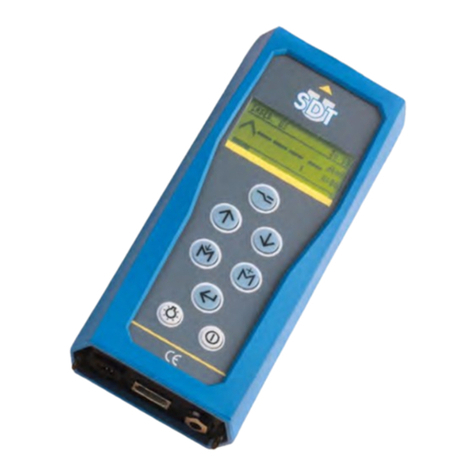
SDT SDT340 User manual

SDT340 User Manual
SDT International sa-nv • Bd de l’Humanité 415 • B-1190 Brussels (Belgium) • Tel : +32(0)2 332 32 25 • email : info@sdtultrasound.com
SDT North America • 7677 County Road 2 •Cobourg ON K9A 0X4 (Canada) • Phone : 1-800-667-5325 | 1-905-377-1313 •email : hearmore@sdtultrasound.com
www.sdtultrasound.com
TANKTEST MODE
USER MANUAL
2022 –Version 1
© SDT International. All rights reserved. Specifications are subject to change without notice.

DC.R340TT.MAN.001—01—User Manual SDT340TANKTEST EN
2/44
Table of Contents
Table of Contents.................................................................................................................................... 2
1. Safety .............................................................................................................................................. 3
2. Caution............................................................................................................................................ 3
3. CE compliance................................................................................................................................. 4
4. Introduction.................................................................................................................................... 5
5. Field of application......................................................................................................................... 5
6. Unpacking ....................................................................................................................................... 7
7. Battery............................................................................................................................................. 7
8. Controls and connections............................................................................................................... 9
8.1. Power On............................................................................................................................... 10
8.2. Sleep Mode............................................................................................................................ 10
8.3. Power Off............................................................................................................................... 10
8.4. Driver..................................................................................................................................... 10
8.5. Plug & Unplug a Sensor......................................................................................................... 10
9. Home screen ................................................................................................................................. 11
10. Tree Structure Mode .................................................................................................................... 12
11. Guided TankTest mode................................................................................................................. 13
12. Measurement in Free mode tab .................................................................................................. 30
13. General settings............................................................................................................................ 31
13.1. System info........................................................................................................................ 32
13.1.1. Device info .................................................................................................................................. 33
13.1.2. License info ................................................................................................................................. 33
13.1.3. Last calibration date ................................................................................................................... 33
13.1.4. Battery info ................................................................................................................................. 34
13.1.5. Hardware info ............................................................................................................................. 34
13.1.6. Software info .............................................................................................................................. 35
13.1.7. Database ..................................................................................................................................... 35
13.1.8. Certifications and markings reminder ........................................................................................ 35
13.1.9. Manufacturer info....................................................................................................................... 36
13.2. Language ........................................................................................................................... 36
13.3. Bluetooth........................................................................................................................... 37
13.4. Date and time format........................................................................................................ 37
13.5. Brightness.......................................................................................................................... 38
13.6. Network............................................................................................................................. 38
13.7. Theme................................................................................................................................ 39
14. Using the TankTest Reporter software........................................................................................ 39
14.1. Exporting your data........................................................................................................... 39
14.2. Cleaning the device memory............................................................................................. 40
14.3. Updates ............................................................................................................................. 41
15. Recommended calibration intervals .................................................................................... 42
16. Warranty............................................................................................................................ 43
17. Responsibility limits............................................................................................................ 43
18. Destruction and recycling of waste equipment .................................................................... 43
19. Copyright............................................................................................................................ 44

DC.R340TT.MAN.001—01—User Manual SDT340TANKTEST EN
3/44
1.Safety
Carefully read this manual before using the SDT340 TankTest. To prevent death or injury risks and
severe damage to the unit and its accessories, use only as specified in this manual. Otherwise, the
protection provided by the instrument might be impaired. Make sure that all instructions are fully
understood and observed.
To avoid personal injury:
•Do not use if damaged.
•Use caution around rotating equipment and keep cords and straps contained.
•Select a safe location for the sensor and proceed with utmost care during its mounting when
taking readings on exposed rotating parts.
•Do not operate around explosive gas, vapor, and dust or in damp or wet environments.
•Use proper protective equipment, as required by local or national authorities
•Do not used the SDT340 in hazardous environments (ATEX environment). Please refer to the
SDT270A (Ex proof version) and its marking before considering these restricted areas in the
field.
•Never look directly to the laser beam. Never point the laser beam at a person's eye. Do not
aim the laser at specular reflection surfaces. Never look the laser using an optical instrument.
The power supply is designed to operate at ambient temperature between 0 °C to 60 °C (32 °F to +140
°F) up to 90% relative humidity, no condensation. Its storage temperature is between -20 °C to +85 °C
(-4 °F to +185 °F). The power supply should never be operated or even stored at places listed below,
because this could lead to operating failures:
•Places heavily exposed to moisture or where water condensing may occur.
•Places subject to constant vibrations or to high temperature fluctuations.
•Outdoors.
2.Caution
Do not disassemble the instrument, the sensors, the battery, the battery docking station, and the
battery power supply. Do not attempt internal alterations. Do not attempt any repairs. Potential
damages will not be covered by the Lifetime Warranty. Contact SDT Ultrasound Solutions or an SDT
Authorized Service Provider.
The permissible ambient temperature range for the operation of the SDT340 is -15 °C to +60 °C (5 °F
to 140 °F). Relative humidity must be less than 90%, non-condensing.
Due to the typical self-discharge rate of NiMH batteries, it is recommended to charge the battery at
least every 3 months, using only the provided charger pack. It is recommended not to store an
uncharged/unused battery for more than a few weeks. This would considerably reduce its lifespan.
The SDT 340 is equipped with a class 2 laser: risk of eye injury
•Never look directly to the laser beam
•Never point the laser beam at a person’ eye
•Do not aim the laser at specular reflective surfaces
•Never view the laser using an optical instrument

DC.R340TT.MAN.001—01—User Manual SDT340TANKTEST EN
4/44
Ultrasound inspectors using SDT instruments with audio outputs are exposed to sounds levels having
noise exposure characteristics daily, which, if not managed by the manufacturer, can increase your risk
of hearing loss. Legislation in Europe has fixed a threshold at 80 dB(A) for a maximum exposure of 8
hours per day.
Government Legislated Noise Exposure Levels
Sound Level dB(A)
Max Exposure Per Day
80
8 hours
83
4 hours
86
2 hours
89
1 hours
92
½ hour
95
15 minutes
98
7.5 minutes
The audio output paired with the Peltor headsets supplied by SDT, having the references FUHDPH-1
and FUHDPH-2 delivers a maximum sound pressure level of 79 dB. SDT makes an additional safety
guarantee to our users. When connecting a sensor, or selecting/changing sensors, SDT instruments
self-adjust the volume to a default, maximum sound pressure level of 58 dB typical. This applies to all
compatible, SDT manufactured sensors and is done so, willingly for the protectionand safety of anyone
who uses our products. At full power, prolonged listening to the audio signal can cause hearing loss
and/or irreversible hearing damage.
3.CE compliance
SDT340 and its accessories have been designed and tested to meet the following directives and
standards. The SDT340 kit meets the essential requirements of the applicable European Directives:
•2014/30/EU; Electromagnetic Compatibility Directive (EMC)
•2011/65/EU; Restriction of Hazardous Substances (RoHS)
•2014/35/EU; Low Voltage Directive (LVD), applied to battery charger
•2006/66/EU; Batteries and accumulators and waste batteries and accumulators
The declaration of CE conformity is available on SDT website at:
https://sdtultrasound.com/support/downloads/certificates/

DC.R340TT.MAN.001—01—User Manual SDT340TANKTEST EN
5/44
4.Introduction
The SDT340 TankTest is a control and diagnostic tool for underground storage tanks. The SDT340
includes the following features:
•Ultrasound and vibration measurements
through 2 input channels
•0 Hz to 100 kHz Bandwidth
•10 minutes record length
•Tree database structure, organized by tank
•3.5” full-color display 320x480
•On-screen Time Waveform
•Signal play back
•256 kHz sample rate, reduced to 32 kHz by
heterodyning
•6.5 GB data memory
•Quick and intuitive navigation through
database nodes associated with tanks
•Recall of historical data in-the-field
•Bluetooth for wireless audio
streaming
5.Field of application
The SDT 340, in its TankTest configuration, embeds a guided procedure, detailing the different steps
of the control of the tightness of an underground storage installation through the acoustic method.
The procedure does not prejudge, in particular:
- The different preliminary operations, emptying, cleaning, degassing of the tank
- The measures to be taken in order to ensure the safety of the personnel and the third parties
- The use of individual and collective protective equipment
- The regulatory measures to be taken in the event of a leak
The procedure is to be used to ensure the following controls, within a regulatory framework:
- The control of the tightness of a tank with a single metal shell. This check is carried out after
cleaning, degassing the tank and reassembling the manhole cover without reconnecting its
pipes.
- The inspection of an installation composed of a single shell tank and its pipes. This tightness
control is performed after cleaning, degassing the tank, reassembling the manhole plate and
reconnecting its associated piping.
- The inspection of the pipes associated with a double shell tank, without cleaning and degassing
of this tank.
In the first two cases, after cleaning the tank, the remaining noble product can be put back in the tank
before its control.
This procedure is adapted to the regulatory control of storage installations used for heating
installations, equipped with tanks and pipes described below, excluding any other type:
1 - NF M88-512 Steel storage tanks - Horizontal tanks for liquid flammable products
2 - NF M88-553 Steel tanks in service with reinforced plastic lining for storage of liquid
petroleum products
3 - EN 12285-1 Steel tanks manufactured in workshops
Part 1: Horizontal cylindrical single and double shell tanks for the underground storage
of flammable and non-flammable water contaminating liquids

DC.R340TT.MAN.001—01—User Manual SDT340TANKTEST EN
6/44
The determination of the vacuum and the admissible product height for acoustic controls, on tanks
meeting the construction standards stated above, is imposed, independently of SDT International.
Nominal
capacity in
liters
Construction
standards
External
diameter
in mm
Nominal
thickness in
mm
Permissible
vacuum in
mbar
Maximum
product
height in m
1500
1 - 2 - 3
1250
5
250
< 1.2
2000
1 - 2 –3
1250
5
250
< 1.2
3000
1 - 2 –3
1250
5
250
< 1.2
4000
1 - 2 –3
1250
5
250
< 1.2
5000
1 - 2 –3
1500
5
250
< 1.4
5500
1 - 2 –3
1500
5
250
< 1.4
6000
1 - 2 –3
1500
5
250
< 1.4
7500
1 - 2 –3
1900
5
250
< 1.8
8000
1 - 2 –3
1900
5
250
< 1.8
10000
1 - 2 –3
1900
5
250
< 1.8
12000
1 - 2 –3
1900
5
250
< 1.8
15000
1 - 2 –3
1900
5
250
< 1.8
20000
1 - 2 –3
2500
6
250
2.2
25000
1 - 2 –3
2500
6
250
2.2
30000
1 - 2 –3
2500
6
250
2.2
35000
1 - 2 –3
2500
6
250
2.2
40000
1 - 2 –3
2500
6 or 7
250
2.2
40000
1 - 2 –3
3000
6 or 7
250
2.2
50000
1 - 2 –3
2500
6 or 7
250
2.2
50000
1 - 2 –3
3000
6 or 7
250
2.2
60000
1 - 2 –3
2500
6 or 7
220
1.8
60000
1 - 2 –3
3000
6 or 7
250
2.2
80000
1 - 2
3000
6
180
1.3
80000
EN 12285-1
3000
7
250
2.2
100000
1 - 2
3000
6
140
0.9
100000
EN 12285-1
3000
7
210
1.7
120000
EN 12285-1
3000
7
180
1.3
This table is also valid for multi-compartment tanks. For these, the total volume of the tank (vacuum
and product height) must be taken into account.

DC.R340TT.MAN.001—01—User Manual SDT340TANKTEST EN
7/44
In particular, thisprocedure is not applicableto tanks that have been convertedto a double shelldesign
using:
- A flexible inner lining.
- Reinforced plastic lining.
For these installations, please follow the instructions of the contractor or applicator.
Caution:
Failure to comply with these normative constraints exposes the operator to risks of
deformation of the tank leading to a destructive test having no regulatory value. SDT
International cannot be held responsible, in case of disregard of the test procedures
6.Unpacking
The items that follow are included in your purchase of the SDT340 TankTest kit. Unpack and inspect
them.
•SDT340
•Wired headset
•Spiral Cable, 2 male 7-pole LEMO
connectors
•TankTest sensors (TTR2, TTB2)
mounted on the Camlock
•Flexible Sensor
•USB communication cable
•USB key containing user manuals
•TankTest reporter software
•Battery pack
•Battery charger, power cord, EU, US
and UK plugs
•Battery docking station
•Shoulder strap
•Multi-function screwdriver
7.Battery
Caution :
Only use the docking station and the power supply provided by SDT.
Do not store an uncharged battery for more than a few weeks.
Perform preferably a complete charge cycle.
Charge the battery at least every 3 months, even not used.
The SDT340 operates on a rechargeable Nickel Metal Hydride (NiMH) battery. After unpacking the unit,
please fully charge the battery pack before its first use. To charge the battery pack:
•Plug the power supply (*) to the main and connect it ❶to the docking station. Then the LED
is blinking blue.
•Loosen the quick fastener using the screwdriver and remove the battery pack from the unit.
•Place the battery pack in the docking station ❸. The LED should stay on blue a few seconds
and then flash green. Otherwise, perform a force charging by inserting a needle in the reset
location ❷.
•When the LED is continuously lit green, the battery is fully charged.

DC.R340TT.MAN.001—01—User Manual SDT340TANKTEST EN
8/44
AC/DC power supply:
Based on XP Power, Model ACM24 series (you may find other
references/brand depending on your order date. Please refer to the
label on the transformer)
Power supply:
Input: 100-240 VAC-0.5 A, 50/60 Hz
Output: 12 VDC-2000 mA, total regulation 5%, efficiency 88.8 %
Operating temperature:
0 to +60 °C (+32 to 140 °F), < 90 % humidity, non-condensing
Storage temperature:
-20 to + 85 °C (-4 to 185 °F)
Output Power:
Max 24 W
Category:
Class II construction
EMC Emissions:
EN 55032, EN 61000-3
EMC Immunity:
IEC 60601-1-2, EN 61204-3, EN 61000-4, EN 60601-1-2
Electrical safety (LVD):
UL 60950-1, UL 62368-1, ANSI/AAMI ES 60601-1
EN 60950-1, EN/IEC 62368-1, EN 60601-1
CSA C22.2 No. 60601
CCC China Compulsory certification, GB4943
AU/NZ 60950.1
CE: meets all applicable directives
UKCA: meets all applicable directives
Weight:
160 grams (0.35 lb)
Dimensions (body only):
88.0 x 30.0 x 57.0 mm (3.46 x 1.18 x2.24’’)
AC input plugs:
UK, US, EU
Reference:
https://www.xppower.com/portals/0/pdfs/SF_ACM24.pdf
❶Power supply connector
❷Force battery charge location
❸Battery pack placed on the docking station
❹Docking Station LED
❸
❷
❹
❶
❷
Force battery
charge

DC.R340TT.MAN.001—01—User Manual SDT340TANKTEST EN
9/44
(*) The primary plug of the
power supply is interchangeable.
The procedure of changing is as
per the pictures.
The color of the docking station status LED ❹shows:
•The LED flashes blue –the docking station is powered.
•The LED remains blue illuminated a few seconds when the battery is placed in the docking
station –the battery is detected.
If not, perform a force charge by inserting a needle in the force battery charge location ❷.
•The LED flashes green –the battery pack is charging.
•The LED is green lit continuously –the battery is fully charged.
•The LED flashes red –the docking station detect an abnormal current consumption or an
abnormal temperature. Disconnect and then reconnect the power supply from the main to
reset the docking station.
The SDT340 autonomy is typically 8 hours for a fully charged battery pack and the recharge time is
about 7 hours.
8.Controls and connections
❶Display
❷F1 to F4. Their respective function is indicated
in the bottom of the display
❸Esc (Escape) for stopping a signal acquisition
and going back to the previous menu through
setting screens
❹Home for displaying the main menu
❺Enter to start the acquisition and validate
changes through setting screens
❻Up, Down, Left and Right navigation keys for
the signal, audio amplification adjustment and
navigation through the settings screens
❼Hold-on laser
❽On/Off
❾Status LED.
Front panel
❶
❷
❸
❹
❼
❻
❽
❾
❺

DC.R340TT.MAN.001—01—User Manual SDT340TANKTEST EN
10/44
❿Laser pointer
⓫Input channels. Black collar for the black TTB2
sensor, red collar for the TTR2 sensor. To plug a
connector, line up the red dot on the plug with the
red mark on the connector. Insert the plug into the
connector without any rotating movement. To
unplug the connector, move up, towards the cable,
the ring located on the bottom of the plug. Only pull
the connector without any rotation.
⓬Wired headset connector, 6.35 mm jack type.
⓭USB type-C Port.
⓮Reset location. Insert a needle, the unit will
restart.
⓯Shoulder strap rings.
Lateral panels
8.1. Power On
Press the Power button ❽. At power up, device information and battery charge are displayed, then
the Home menu is displayed on the screen.
8.2. Sleep Mode
After a few minutes of inactivity, the screen is powered off for battery saving and the status LED is
blinking green. Press any key to reactivate the display.
8.3. Power Off
Press the Power button ❽. At the prompt, select Yes with the Left navigation key ❻, or No to
continue with the operation. Confirm using Enter ❺.
8.4. Driver
The USB driver is automatically installed from the 340, once connected to your PC.
In case of synchronization issue, the driver file SDT2xxDriverinstaller.exe can download from our
website, by clicking this link.
8.5. Plug & Unplug a Sensor
SDT 340 has 2 input ports with 7-pole LEMO connectors for external sensors. The channel with the red
collar is dedicated to the sensor to be immersed in the liquid as the black one is reserved for the
airborne sensor.
LEMO connectors have a sprung-loaded knurled barrel and a coding device to make the connection
easier.
To plug a LEMO connector, line up the red dot on the plug with the red mark on the connector. Insert
the plug into the connector without any rotating movement.
To unplug, move up the ring located on the bottom of the plug. Be sure to only pull the connector
without any rotation and to never pull on the cable itself.
❿
⓫
⓭
⓬
⓮

DC.R340TT.MAN.001—01—User Manual SDT340TANKTEST EN
11/44
9.Home screen
Connect the sensors to the SDT340 to display the icons associated with the TankTest mode
❶Tree Structure Data Collection Mode
❷General Settings
❸Guided tank inspection procedure
The icon is available with the 340 TankTest
provided that both sensors are connected,
in the right order
❹Direct access to the airborne sensor
❺Direct access to the immersed sensor
❻Battery status
❼Audio output (default is mute)
❽USB connection established with the PC
❾Connected headset
❿Time and date scrolling information
(synchronized with your PC)
The Home screen is displayed a few seconds after the device is turned on.
On top left, date and time are scrolling ❿. On the top right are the connectivity icons (when activated),
USB ❽(when the SDT340 is connected to a computer), wireless headset (when paired), wired headset
(when connected) ❾and battery status ❻.
Use the navigation keys to select an icon and press Enter to validate your choice. The selected icon is
indicated by a bottom orange line (cf. ❶).
Press Home to directly come back to the Home screen from any menu.
When no sensor is connected to the device, the ❸❹❺ icons are not displayed and the sound icon
❼is blocked without the ability to adjust the volume. However, the user hears background noise
emanating from the internal electronics.
Caution:
It is necessary to connect the two TankTest sensors in the right inputs to display the
guided mode icon and the widgets associated with the sensors
The flexible sensor for leak detection can be connected to the black input. Once connected and
recognized by the device, the icon allows access to the real-time measurements of the flexible
sensor.
❶
❷
❸
❹
❺
❻
❼
❽
❾
❿

DC.R340TT.MAN.001—01—User Manual SDT340TANKTEST EN
12/44
10. Tree Structure Mode
In this mode, the SDT340 TankTest shows the tests already performed and the status of the database.
Access the mode from the home screen, by clicking on the icon and then pressing Enter.
The tree structure mode contains a directory of 50 locations for storing TankTest test data. Only the
guided mode, described below, allows this tree structure to be filled. An occupied memory location
contains the reference measurements "Ref", as well as the measurements supposedly acquired in
vacuum "Test", for each sensor. The measurements are recorded in UTC time.
❶"Tree Structure" mode
❷Test performed/memory location
occupied. The details entered by the
operator when taking the measurements
are recalled by pressing the ENTER key
❸Selected memory location
❹Empty memory locations
❺Access to reference measurements
associated with the location❸(if existing)
❻Access to vacuum measurements
associated with the location❸(if existing)
In tree structure mode, the user only has the possibility to browse the already occupied memory
locations to revisit/play back the different measurements.
Tightness control through the acoustic method requires to pass successively from one sensor to the
other, at ambient pressure and then under imposed vacuum. Each step is recorded in the memory of
the device, according to the following logic:
•TankID: Tank Identification
oRef: Reference measurements
▪TTR2(RW-32k): with the red sensor, in liquid phase
❶
❷
❸
❹
❺
❻
Tree Structure

DC.R340TT.MAN.001—01—User Manual SDT340TANKTEST EN
13/44
▪TTB2(Ht-32k): with the black sensor, in airborne phase
oTest: Vacuum measurements
▪TTR2(RW-32k): with the red sensor, in liquid phase
▪TTB2(Ht-32k): with the black sensor, in airborne phase
The example below, applied to the "Tank1" memory location, describes the tree structure mode
readback options.
❶Access to reference measurements
❷View Toggle screens with F2 key
(ST(RMS) view, TIME (signal) view)
In TIME view, the operator can listen to the
audible signal again with the F4 key or
check the 10 most important samples with
the F1 key.
❸Reminder of the sensor configuration
The user is not allowed to modify the measurement parameters or to create a new measurement
within the tree structure.
The user must refer to the TankTest reporter software manual to manage his data and generate
reports.
11. Guided TankTest mode
The guided mode breaks down the acoustic tightness test into several mandatory steps. The operator
is invited to interact with the instrument, taking note of the different screens.
❶
❷
❸

DC.R340TT.MAN.001—01—User Manual SDT340TANKTEST EN
14/44
All settings are predefined to make the test quick and intuitive, while collecting data of interest that
will be recorded in a final report.
From the Home screen, select the icon and press Enter.
The first screen reminds:
1. That the SDT340 equipment and its accessories are not designed to be used in ATEX zones.
2. That the TankTest sensors must not be disconnected during a guided test, otherwise the
measurements will be lost. Disconnecting sensors during a non-finalized test will cause the
mode to be closed.
Make sure you have all the necessary equipment and authorizations before starting a new acoustic
tightness test.

DC.R340TT.MAN.001—01—User Manual SDT340TANKTEST EN
15/44
❶Access to the guided TankTest mode
❷Usage reminders
❸User choice: Leak simulator.
In practice, the leak simulator is used at the
end of the test as a functional test of the
equipment, in the presence of a calibrated
flow.
By choosing yes, a message will explicitly ask
you to use this equipment at the end of the
vacuum measurements.
Refer to the regulations in place in your
country to know if this functional test tool is
mandatory or optional.
❹Go to the next step with the F3 key
The next screen invites the operator to choose a memory location where the measurements associated
with the TankTest test will be stored.
❶
❷
❸
❹

DC.R340TT.MAN.001—01—User Manual SDT340TANKTEST EN
16/44
❶Node or memory location occupied
❷Node or memory location selected
❸Remaining nodes or memory locations
❹Go to the next step with the F3 key.
Confirm the selected choice with ENTER
The screen summarizes the acquisition time settings. It is only possible to adjust the acquisition time
of the sensors in "TEST" mode. The references associated with the respective background noises of the
sensors, on the day of the test, before application of the vacuum are determined on the basis of an
acquisition time fixed at 6 seconds, per sensor.
The amplification is preset to +90 dB and will adjust automatically. Adjust the audio volume using the
Left Arrow and Right Arrow keys.
On each sensor, the RMS value is automatically updated 2 times per second.
❶
❷
❸
❹

DC.R340TT.MAN.001—01—User Manual SDT340TANKTEST EN
17/44
❶Field associated with the
determination of the reference levels
(REF), before application of the vacuum.
Not configurable
❷Field associated with the
measurements, in vacuum (TEST)
Configurable by the operator, between 20
seconds and 10 minutes, 120 seconds by
default
Refer to your country's regulations
❸Go to the next step with the F3 key.
Confirm the selected choice with Enter
The next step is to fill in the information about the tank to be checked.
Before starting a test, it is usual to proceed to the gauge of the height of the liquid and water by means
of a pin inserted by the mechanical sleeve.
❶
❷
❸

DC.R340TT.MAN.001—01—User Manual SDT340TANKTEST EN
18/44
❶Diameter of the tank, in mm
❷Height of the liquid, before the test
❸Height of water, before the test
❹Go to the next screen with F3
Before proceeding with the installation of the sensors, the following points should be noted:
- The sensors should be handled with care, especially on their sensitive side.
- The sensors are supplied pre-wired on the Camlock. The adjustment of the lengths described
in the next step implies manual tightening, using the cable glands located on the Camlock, in
order not to damage the seals of the device.
Sensitive side of the TankTest sensors
Detail of the position of the sensors
❶
❷
❸
❹
Sensitive side

DC.R340TT.MAN.001—01—User Manual SDT340TANKTEST EN
19/44
❶Place the position of the sensors in the
tank
Tightening must be done MANUALLY at the
cable glands located on the Camlock.
❷Return to the previous step with F2
❸Go to the next step with F3
The adjustment of the sensor position is explained below:
- Adjust the height of the BLACK sensor (TTB2) so that its sensitive side is located at the level of
the connection of the bottom of the flange to the tank shell.
- Adjust the height of the RED sensor (TTR2) so that its sensitive side is immersed in the liquid,
without touching the bottom of the tank. The amount of liquid must be sufficient to allow the
sensor to be fully immersed.
❶
❷
❸

DC.R340TT.MAN.001—01—User Manual SDT340TANKTEST EN
20/44
❶Isolate the installation to be controlled
Follow the instructions on the screen
- Seal the "open" parts of the installation
with plugs
- Install the leak simulator between the
camlock and the tank, if selected in step 1
and close its valve
- Lock the Camlock and the leakage
simulator to the system
❷Return to the previous step with F2
❸Go to the next step with F3
❶
❷
❸
❷
❸
Other manuals for SDT340
1
Table of contents
Other SDT Measuring Instrument manuals
SDT
SDT HATCHecker User manual
SDT
SDT ULTRAChecker User manual

SDT
SDT SDT340 User manual

SDT
SDT SDT270 Pro 3 User manual

SDT
SDT SDT270 TankTest User manual

SDT
SDT Vigilant User manual
SDT
SDT LEAKChecker User manual
SDT
SDT T-Sonic9 User manual

SDT
SDT Sherlog Kit Master SDT270 User manual

SDT
SDT Vigilant User manual
