manuals.online logo
Brands
  1. Home
  2. •
  3. Brands
  4. •
  5. GE
  6. •
  7. Measuring Instrument
  8. •
  9. GE RHM 04 User manual

GE RHM 04 User manual

RHM 04
g
The RHM 04 can measure ow rates up to 10 kg/min
(22 lb/min) with extremely fast response times and
excellent repeatability. A very high pressure version
up to 1067 bar is also available, manufactured by
GE’s Rheonik mass owmeter experts.
Applications
• General control • Dosing • Mixing
• Batching • Injections • Filling
Features
• Available as very high pressure version up to 1067
bar
• Response times of 30 ms and better
• Flow uncertainty down to 0.10%
• Repeatability better than 0.05%
• Unique torsion oscillator
• Typical measuring ranges from 0.1 to 10 kg/min
• Minimal ows as low as 50 g/min
• Customization possible
• Extra compact design with minimal space
requirement
• Hazardous Area Approvals (ATEX, CSA, ...)
Versatile Coriolis Mass
Flowmeter with Fast
Response Times for Very
High Pressure Applications
Advantages
• Torsion oscillator design assures most stable and
basically drift free measurement and increased
signal to noise ratio
• Not sensitive to changes in pressure
• Longest life time and increased safety (low stress
in welds and increased wall thickness against
abrasion)
• No moving parts, practically no maintenance
• Removable connection manifold available
GE
Measurement & Control
General Dimensions RHM 04
PM0/SM0 (parallel/serial, manifold construction)
Process Connection Face to face length (L) Order Code
mm in
Standard Flange DIN DN15/PN40 220 8.66 D1
Flange DIN DN15/PN100 220 8.66 D2
Flange ANSI ½" 150# RF/SF 220 8.66 A1
Flange ANSI ½" 300# RF/SF 220 8.66 A2
Flange ANSI ½'' 600# RF/SF 220 8.66 A3
Flange ANSI ½" 1500# RF/SF 300 11.81 A6
Flange ANSI ½'' 1500# RTJ 300 11.81 R1
Optional Flange DIN DN15 / PN 160 220 8.66 D3
Flange JIS RF 10k 15A (1/2") 220 8.66 J1
Flange JIS RF 20k 15A (1/2") 220 8.66 J2
Type removable manifold with PTFE seals and ange connection
H1 = 173 mm (6.79 in)
H2 = 189 mm (7.44 in)
PM0/SM0/PH0 (parallel/serial, manifold construction with
thread connection)
Process Connection Face to face length (L) Order Code
mm in
PM0/SM0
Standard
Female Thread G ¼" 50 1.97 G1
Female Thread ¼" NPT 50 1.97 N1
PH0
Standard
Female Thread G ¼" 70 2.76 G1
Female Thread ¼" NPT 70 2.76 N1
Autoclave 3/8" MP (9/16-18
UNF female thread)
70 2.76 P2
Type parallel, very high pressure manifold with PTFE seals and thread connection
(orientation upwards)
H1 = 184 mm (7.24 in)
A = 28 mm (1.10 in)
D = 6.5 mm (0.26 in)
L1 = 160 mm (6.30 in)
A1 = 130 mm (5.12 in) B1 = 25 mm (0.98 in) Terminal box (without cable gland) 125 x 80 x 58 mm (4.92 x 3.15 x 2.28 in)
A2 = 145 mm (5.71 in) B2 = 40 mm (1.57 in) W = 0 mm for Temperature Range T1 and TA
W = 100 mm (3.94 in) for Temperature Range T2
For weights and packaging dimensions please see last page of this section.
Process Connection Overall Height (H) Order Code
mm in
Standard Autoclave 3/8" MP (9/16-18
UNF female thread)
234 9.21 P2
2
Type removable manifold with PTFE seals and thread connection
PM0/SM0
H1 = 173 mm (6.79 in)
H2 = 189 mm (7.44 in)
PH0 (high pressure manifold construction)
H1 = 184 mm (7.24 in)
H2 = 204 mm (8.03 in)
PHH (parallel, very high pressure manifold construction)
General Dimensions RHM 04
PF0 (parallel, sealless construction with ange
connection)
Type parallel, welded measuring loops without seals and ange connection
Process Connection Face to face length (L) Order Code
mm in
Standard Flange DIN DN15/PN40 220 8.66 D1
Flange DIN DN15/PN100 220 8.66 D2
Flange ANSI ½" 150# RF/SF 220 8.66 A1
Flange ANSI ½" 300# RF/SF 220 8.66 A2
Flange ANSI ½'' 600# RF/SF 220 8.66 A3
Flange ANSI ½" 1500# RF/SF 300 11.81 A6
Flange ANSI ½'' 1500# RTJ 300 11.81 R1
Optional Flange DIN DN15 / PN160 220 8.66 D3
Flange DIN DN25 / PN160 260 10.24 D4
Flange ANSI ½" 2500# RF/SF 300 11.81 A8
Flange JIS RF 10k 15A (1/2") 220 8.66 J1
Flange JIS RF 20k 15A (1/2") 220 8.66 J2
Grayloc Hub 1 GR4 (1") 300 11.81 H3
PFT (parallel, sealless construction with thread
connection)
Process Connection Face to face length (L) Order Code
mm in
Standard Female Thread G ¼" 220 8.66 G1
Female Thread ¼" NPT 220 8.66 N1
Swagelok ¼" tube inlet (SS-
400-1-4W)
300 11.81 W1
Type parallel, welded measuring loops without seals and thread connection
A1 = 130 mm (5.12 in) B1 = 25 mm (0.98 in) Terminal box (without cable gland) 125 x 80 x 58 mm (4.92 x 3.15 x 2.28 in)
A2 = 145 mm (5.71 in) B2 = 40 mm (1.57 in) W = 0 mm for Temperature Range T1 and TA
H1 = 173 mm (6.79 in) W = 100 mm (3.94 in) for Temperature Range T2, T3 and T4
H2 = 205 mm (8.07 in)
For weights and packaging dimensions please see last page of this section.
3
4
General Dimensions RHM 04
SF0 (serial, sealless construction without dead spaces) (*)
Type single path, welded measuring loops without seals and sanitary connection
H2 = 184 mm (7.24 in)
Process Connection Face to face length (L) Order Code
mm in
Standard Sanitary ½" Triclamp, DIN
32676
220 8.66 S1
Sanitary NW10, DIN 11851 220 8.66 S2
Process Connection Face to face length (L) Order Code
mm in
Standard Flange DIN DN15/PN40 220 8.66 D1
Flange ANSI ½" 150# RF/SF 220 8.66 A1
Flange ANSI ½" 300# RF/SF 220 8.66 A2
Optional Flange ANSI ½'' 150# RTJ 220 8.66 R3
Type single path, welded measuring loops without seals and ange connection
H2 = 205 mm (8.07 in)
A1 = 130 mm (5.12 in) B1 = 25 mm (0.98 in) Terminal box (without cable gland) 125 x 80 x 58 mm (4.92 x 3.15 x 2.28 in)
A2 = 145 mm (5.71 in) B2 = 40 mm (1.57 in) W = 0 mm for Temperature Range T1 and TA
H1 = 173 mm (6.79 in) W = 100 mm (3.94 in) for Temperature Range T2, T3 and T4
(*) SF0 construction contains brazed joints (brazing material B-Ni82CrSiBFe-970/1000) which are not as corrosion resistant as the piping material 1.4571 (316Ti).
Weight in standard manifold construction with female threads: approx. 2.5 kg (5.5 lb)
Weight in standard sealless construction and 150# anges: approx. 3.5 kg (7.7 lb)
Shipping in carton box approx. 60 x 41 x 32 cm (24 x 16 x 13 in), gross weight with sealless construction, 150# standard anges and RHE 08 approx. 10 kg (22 lb)
Finish type of our ANSI anges corresponds to SF (AARH 125 up to 250 μin, Ra 3.2 up to 6.3 μm)
For customization with regard to face to face length and special ttings, please consult your local agent
Please note that larger diameter process connections are always possible
5
Pressure Rating RHM 04
The maximum pressure (pmax) of a sensor is determined by its weakest part. The weakest part can be the measuring
loops (pmax indicated below) or the construction type (pmax indicated in the Basic Order Code section, last page) or the
selected anges / ttings (for pmax please see respective standard).
pmax of P1 measuring loops, standard
M0 standard material - 1.4539 (904 L)
OD x WT 4.5 x 0.3 mm (0.18 x 0.012 in)
bar °C psi °F
170 50 2466 122
150 120 2176 248
120 210 1740 410
100 350 1450 662
pmax of P1 measuring loops
M3 optional material - 2.4602 (Alloy C22)
OD x WT 4.5 x 0.3 mm (0.18 x 0.012 in)
bar °C psi °F
215 50 3118 122
190 120 2756 248
153 210 2219 410
128 350 1856 662
pmax of P2 measuring loops
M0 standard material - 1.4539 (904 L)
OD x WT 4.5 x 0.5 mm (0.18 x 0.02 in)
bar °C psi °F
295 50 4279 122
250 120 3626 248
200 210 2901 410
170 350 2466 662
pmax of PH measuring loops
HP optional material - HP160
OD x WT 4.5 x 0.9 mm (0.18 x 0.035 in)
bar °C psi °F
1067 20 15476 68
900 50 13053 122
870 120 12618 248
pmax of P1 measuring loops*
M1 optional material - 1.4571 (316 Ti)
OD x WT 4.5 x 0.3 mm (0.18 x 0.012 in)
bar °C psi °F
156 50 2263 122
*Only for T3 temperature rating
Performance RHM 04
Max Flow Rate Qmax and Qnom (*) = 10 kg/min (22 lb/min)
Standard Models
Flow Rate Uncertainty
kg/min lb/min in % of reading
10.0 22.05 0.20
7.0 15.43 0.20
4.0 8.82 0.20
0.5 1.10 0.20
0.2 0.44 0.50
Goldline Models (**) - selected sensors
Flow Rate Uncertainty
kg/min lb/min in % of reading
10.0 22.05 0.10
7.0 15.43 0.10
4.0 8.82 0.10
1.0 2.20 0.10
0.5 1.10 0.12
Low Flow Models (**) - selected sensors
Flow Rate Uncertainty
kg/min lb/min in % of reading
4.0 8.82 0.20
2.0 4.41 0.20
1.0 2.20 0.20
0.2 0.44 0.20
0.1 0.22 0.60
Repeatability
Better ± 0.1% of rate,
Goldline 0.05%
Temperature
Better ± 1°C
(*) Nominal ow Qnom refers to roughly 8 - 10
m/s (33 ft/s) velocity in measuring loops for best
performance.
(**) Selected sensors are only available in combination
with temperature options T1, TA, standard material and
pressure range.
• Serial/single path versions oer the same accuracy at
half the ow (Qmax serial version = 5 kg/min).
• No relevant pressure eect due to torsional oscillation
and semi-circle (non-deforming) measurement
section.
• Uncertainty of reading (incl. zero drift) indications refer
to reference conditions H2O, 18-24°C (66 - 76°F), 1 - 3
bar (15 – 45 psi) and installation according to eld
manual.
• Pressure drop indications refer to H2O, with parallel
measuring loops type P1 and standard manifold block
connections.
• For calibration to customer range and / or with
improved uncertainty, please consult factory.
Uncertainty % DP (bar)
Flow Rate kg/min
Uncertainty % DP (bar)
Flow Rate kg/min
Uncertainty % DP (bar)
Flow Rate kg/min
6
General Specications RHM 04
Temperature Range
• NT Models from -20 to +120°C (-4 to +248°F)
• ET Models from -45 to +120°C (-49 to +248°F)
• ET2 Models from -45 to +210°C (-49 to +410°F)
• ET1 Models from -196 to +50°C (-320 to +122°F)
• HT Models from 0 to 350°C (+32 to +662°F)
(Heating for housing optional, please consult your local
agent)
Electrical Connection
• Junction box Aluminium coated (standard). Junction box
in SS 316Ti optional
• Cable entry M25 x 1.5. Optional cable entries M20 x 1.5,
1/2” NPT or 3/4” NPT
• Max cable length between RHM and RHE is 100m
(330 ft). 200m (660 ft) only with factory approval
Material of Wetted Parts
• 1.4539 / SS 904 L / UNS N08904 (standard measuring
loops material)
• 1.4571 / SS 316 Ti / UNS S31635 (standard connection
part material, optional measuring loops material)
• 2.4602 / Alloy C22 / UNS N06022
• HP 160
• Others on request
Sensor Enclosure/Housing
• Stainless Steel 1.4301 / SS 304, optional in 1.4571 / SS
316Ti. Others on request
• Protection Class IP 65. Optional IP 66 / NEMA 4x
Approvals
• ATEX (CESI 02 ATEX 053 X) Ex II 1 G, EEx ia IIC T6-T1
• CSA USA-Canada, Class I, Div. 1, Groups A, B, C, D
• PED according to directive 97/23/EC Art.3 (3) Sound
Engineering Practice (SEP)
• Others on request
7
920-493A
© 2013 General Electric Company. All Rights Reserved. Specications are subject to change without notice. GE is a registered trademark of General Electric Company. Other company or product
names mentioned in this document may be trademarks or registered trademarks of their respective companies, which are not aliated with GE.
gwww.ge-mcs.com
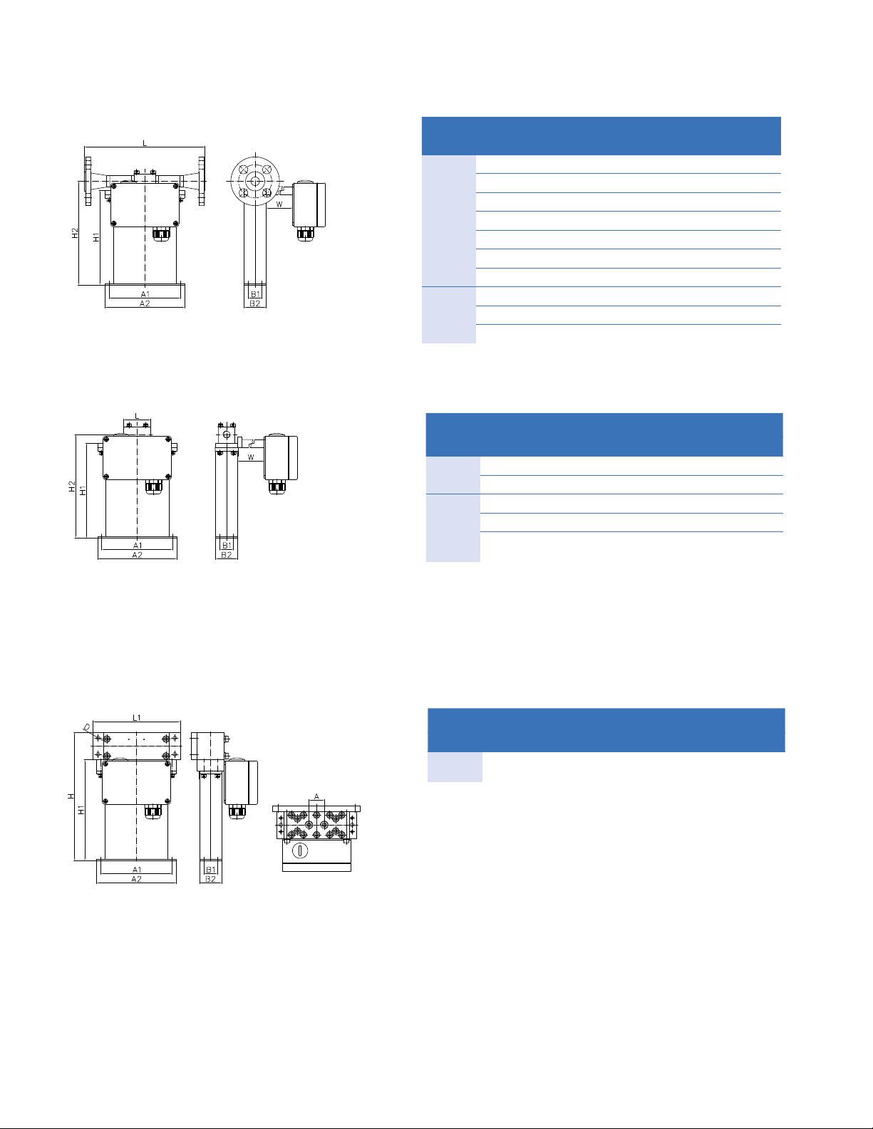
Basic Order Code RHM 04
Sensor Size
Temperature Range
T1 NT from -20°C to +120°C (standard)
TA ET from -45°C to +120°C
T2 ET2 Extended Temperature Range from -45°C to +210°C
T3 ET1 Extended Temperature Range from -196°C to +50°C
T4 HT High Temperature Range from 0°C to +350°C
Pressure Range of Measuring Loops @ 120°C
P1 pmax = 150 bar, M0 Material (standard)
P2 pmax = 250 bar, M0 Material
PH pmax = 870 bar, HP Material
Construction Type (pmax indications @ 120°C)
PM0 Parallel Measuring Loops with removable Manifold and PTFE Seals,
pmax = 400 bar with thread connection, 214 bar with ange connection
SM0 Serial Measuring Loops with removable Manifold and PTFE Seals
pmax = 400 bar with thread connection, 214 bar with ange connection
PF0 Parallel Measuring Loops Seal Less Version
SF0 Serial Measuring Loops Seal Less Version, pmax = 42.9 bar
PFT Parallel Measuring Loops Seal Less Version for Thread Connection, pmax = 530 bar
PH0 Parallel Measuring Loops with High Pressure Manifold and PTFE Seals, pmax = 540 bar
PHH Parallel Measuring Loops with Very High Pressure Manifold and PTFE Seals,
pmax = 870 bar
Material of Wetted Parts
M0 Measuring Loops 1.4539 (904L), Manifold/Connection 1.4571 (316Ti) (standard)
M1 Measuring Loops and Manifold/Connection 1.4571 (316Ti)
M3 Measuring Loops and Connection Part 2.4602 (Alloy C22), Seal Less Construction
Types only
HP Measuring Loops HP 160; not with PF0, SF0, PFT Construction Type
Process Connection
D1 Flange DIN DN15/PN40 Form C
D2 Flange DIN DN15/PN100 Form E
A1 Flange ANSI ½” 150# RF/SF
A2 Flange ANSI ½” 300# RF/SF
A3 Flange ANSI ½’’ 600# RF/SF
R1 Flange ANSI ½’’ 1500# RTJ
A6 Flange ANSI ½” 1500# RF
G1 Female Thread G ¼”
N1 Female Thread ¼” NPT
W1 Swagelok ¼” tube inlet (SS-400-1-4W) - valid for SS only
S1 Sanitary ½” Triclamp, DIN 32676, pmax = 40 bar @ 120°C
S2 Sanitary NW10, DIN 11851, pmax = 40 bar @ 120°C
P2 Autoclave 3/8” MP (9/16-18 UNF female thread)
Others on request
RHM 04 - - - -

Other GE Measuring Instrument manuals

GE DigitalFlow DF868 User manual

GE

GE DigitalFlow DF868 User manual

GE SEER 1000 User manual

GE

GE SEER 1000 User manual

GE Moisture Target Series 6 User manual

GE

GE Moisture Target Series 6 User manual

GE PanaFlow Z1G User manual

GE

GE PanaFlow Z1G User manual

GE AED Pro User manual

GE

GE AED Pro User manual

GE Multilin EPM 2200 User manual

GE

GE Multilin EPM 2200 User manual

GE DewPro MMY 245 User manual

GE

GE DewPro MMY 245 User manual

GE Precision 500D User manual

GE

GE Precision 500D User manual

GE DigitalFlow GS868 Installation guide

GE

GE DigitalFlow GS868 Installation guide

GE RHM 03 User manual

GE

GE RHM 03 User manual

GE Protimeter Timbermaster User manual

GE

GE Protimeter Timbermaster User manual

GE RSDetection RS-S131-200-ER0000 User manual

GE

GE RSDetection RS-S131-200-ER0000 User manual

GE CTF878 Troubleshooting guide

GE

GE CTF878 Troubleshooting guide

GE DigitalFlow GF868 User guide

GE

GE DigitalFlow GF868 User guide

GE 940 User manual

GE

GE 940 User manual

GE DigitalFlow XGM868i User guide

GE

GE DigitalFlow XGM868i User guide

GE Kelman DGA 900 Plus Guide

GE

GE Kelman DGA 900 Plus Guide

GE RHM 20 User manual

GE

GE RHM 20 User manual

GE Kelman MULTITRANS User manual

GE

GE Kelman MULTITRANS User manual

GE CB Watch 3 User manual

GE

GE CB Watch 3 User manual

GE MOA 280i User manual

GE

GE MOA 280i User manual

GE AquaTrans AT600 User manual

GE

GE AquaTrans AT600 User manual

GE MFE DMS 2 User manual

GE

GE MFE DMS 2 User manual

GE N60 User manual

GE

GE N60 User manual

Popular Measuring Instrument manuals by other brands

GARO GNM3D-RS485 Installation and programming manual

GARO

GARO GNM3D-RS485 Installation and programming manual

Wicked lasers S3 Krypton Series user manual

Wicked lasers

Wicked lasers S3 Krypton Series user manual

PeakTech 1650 Operation manual

PeakTech

PeakTech 1650 Operation manual

Industrial physics sheen DV2300 operating instructions

Industrial physics

Industrial physics sheen DV2300 operating instructions

Cal Test Electronics CT4422 user guide

Cal Test Electronics

Cal Test Electronics CT4422 user guide

Rigol RP1003C user guide

Rigol

Rigol RP1003C user guide

Burkert ELEMENT 8228 operating instructions

Burkert

Burkert ELEMENT 8228 operating instructions

Samoa 415000 Technical service guide

Samoa

Samoa 415000 Technical service guide

Industrial Scientific Ventis MX4 Operation manual

Industrial Scientific

Industrial Scientific Ventis MX4 Operation manual

Dwyer Instruments 250-AF Series Installation and operating instructions

Dwyer Instruments

Dwyer Instruments 250-AF Series Installation and operating instructions

TFA 38.2052.02 instruction manual

TFA

TFA 38.2052.02 instruction manual

Fisher Scientific Fisherbrand accumet AB330 user manual

Fisher Scientific

Fisher Scientific Fisherbrand accumet AB330 user manual

Endress+Hauser Proline Promass 84F technical information

Endress+Hauser

Endress+Hauser Proline Promass 84F technical information

Dynamica HALO DB-20 instruction manual

Dynamica

Dynamica HALO DB-20 instruction manual

Kvarts DRSB-01 quick start guide

Kvarts

Kvarts DRSB-01 quick start guide

Crystal Instruments Coco-80 quick reference

Crystal Instruments

Crystal Instruments Coco-80 quick reference

Siemens SITRANS FM100 operating instructions

Siemens

Siemens SITRANS FM100 operating instructions

Rixen SR-496 instruction manual

Rixen

Rixen SR-496 instruction manual

manuals.online logo
manuals.online logoBrands
  • About & Mission
  • Contact us
  • Privacy Policy
  • Terms and Conditions

Copyright 2025 Manuals.Online. All Rights Reserved.