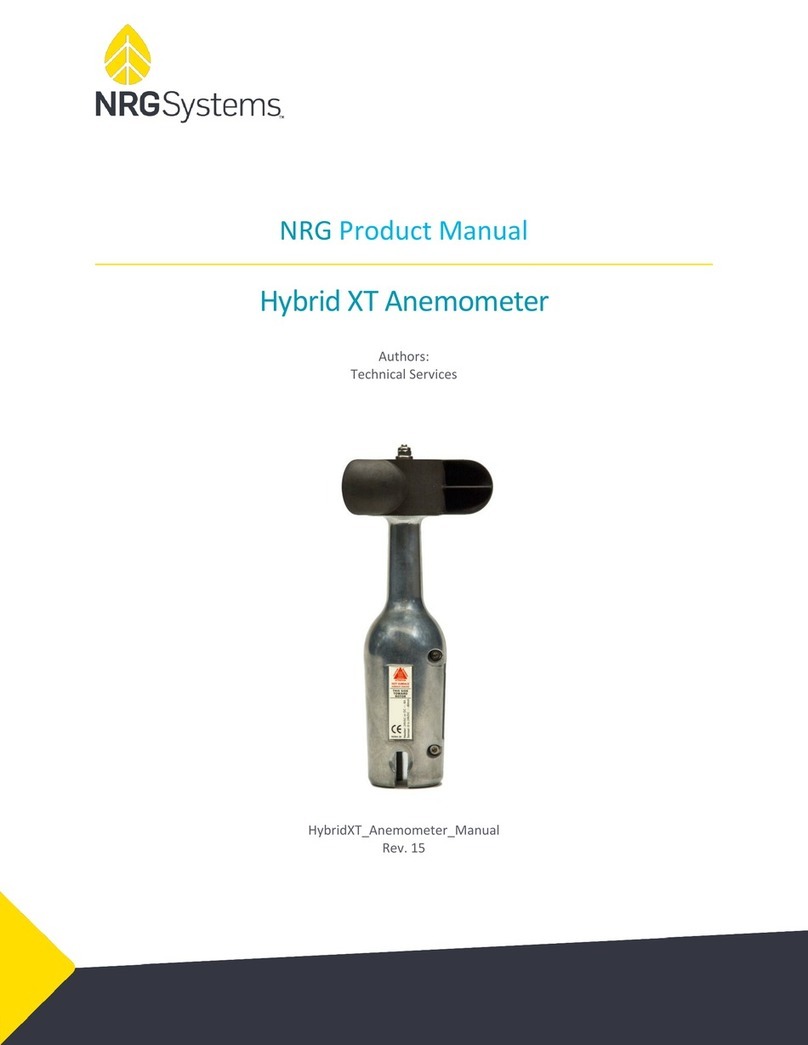
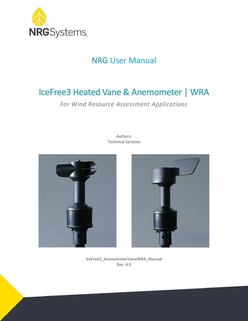
NRG Systems HYBRID XT VANE WRA User manual


NRG User Manual
Hybrid XT Vane & Anemometer | WRA
Hybrid_ XT_Vane_&_Anemometer_WRA_Manual
Rev. 4.0
support@nrgsystems.com | Page 2
TABLE OF CONTENTS
Customer Support....................................................................................................................4
Introduction.............................................................................................................................5
Transport and Handling............................................................................................................5
Sensor Identification ................................................................................................................5
Electrostatic Discharge (ESD) & Circuit Protection .....................................................................5
Using This Manual....................................................................................................................6
Hybrid XT Anemometer............................................................................................................7
Operation ...................................................................................................................................................... 7
Calibration.....................................................................................................................................................7
Hybrid XT Vane ........................................................................................................................7
Operation ...................................................................................................................................................... 7
South Mark....................................................................................................................................................7
Sensor Heater ..........................................................................................................................8
Operation ...................................................................................................................................................... 8
Power Considerations....................................................................................................................................8
Heater Power Supply Requirements ..............................................................................................................8
Sensor Power Supply Requirements............................................................................................................... 9
Sensor Installation.................................................................................................................. 10
Parts Required............................................................................................................................................. 10
Mounting Mast Orientation.................................................................................................... 12
Prepare Shield........................................................................................................................ 12
Mount Connector................................................................................................................... 13
Mount Sensor ........................................................................................................................ 14
Vane:........................................................................................................................................................... 15
Note: This configuration requires the external sense resistor NRG # 17884 (RES 125 OHM 1-2W 0.1% Axial)
.................................................................................................................................................................... 15
Boom bearing should be entered as actual, based on the site. Vane Mounting Angle is always
270 based on the bolt hole alignment, if "toward rotor" is away from the tower. Vane
Mounting Angle would be 90 if "toward rotor" is towards the tower............................................. 15
Logger Wiring:............................................................................................................................................. 15
Logger Programming................................................................................................................................... 16
Anemometer: .............................................................................................................................................. 16
Vane:........................................................................................................................................................... 16

NRG User Manual
Hybrid XT Vane & Anemometer | WRA
Hybrid_ XT_Vane_&_Anemometer_WRA_Manual
Rev. 4.0
support@nrgsystems.com | Page 3
Note: This configuration requires the external sense resistor NRG # 17884 (RES 125 OHM 1-2W 0.1% Axial)
.................................................................................................................................................................... 16
Boom bearing should be entered as actual, based on the site. Vane Mounting Angle is always
270 based on the bolt hole alignment, if "toward rotor" is away from the tower. Vane
Mounting Angle would be 90 if "toward rotor" is towards the tower............................................. 16
Logger Wiring:............................................................................................................................................. 17
Junction Box Wiring..................................................................................................................................... 17
Transformer Wiring ..................................................................................................................................... 19
Sensor Maintenance.................................................................................................................................... 19
Sensor Diagrams | Wind Vane #5762 ...................................................................................... 20
Table of Specifications | Wind Vane #5762 ............................................................................. 21
Table of Specifications | Anemometer #4718.......................................................................... 24
Power Requirements:............................................................................................................. 26
Two Year Limited Warranty.................................................................................................... 27

NRG User Manual
Hybrid XT Vane & Anemometer | WRA
Hybrid_ XT_Vane_&_Anemometer_WRA_Manual
Rev. 4.0
support@nrgsystems.com | Page 4
Customer Support
NRG Systems offers a variety of support options to help you get the most from your NRG
Systems product. If you have questions about your NRG Systems product, first look in the
product documentation and Knowledge Base contained in the Tech Support section of the NRG
Systems web site. If you cannot find the answer, contact your salesperson or NRG Systems
Technical Support for assistance using the information below. Customer support is available
8:30 AM to 5:00 PM EST, Monday through Friday.
NRG Systems
110 Riggs Road
Hinesburg, Vermont,
05461
USA
T | 802-482-2255
When you call or email, you should have the appropriate product documentation at hand and
be prepared to give the following information:
•Customer name
•Item number or description
•Serial number
•When equipment was purchased
•Where equipment is installed - terrain conditions
•Description of the problem with some detail
•What events took place leading up to the problem?
•What you have tried while attempting to solve the problem
NRG Systems maintains an extensive website which includes an in-depth customer
support area for NRG Systems customers. If you need assistance at times other than our regular
business hours, we suggest visiting our website, www.nrgsystems.com.
All instruments, sensors, software, and towers manufactured by NRG Systems are
designed to be reliable and easy to use. We welcome your comments and appreciate your help
in making NRG Systems products the best available.

NRG User Manual
Hybrid XT Vane & Anemometer | WRA
Hybrid_ XT_Vane_&_Anemometer_WRA_Manual
Rev. 4.0
support@nrgsystems.com | Page 5
Introduction
The Hybrid XT anemometer and wind direction vane are proven and reliable heated sensors
ideal for maximizing wind measurement data availability on meteorological towers in climates
that experience frequent icing. The Hybrid XT anemometer and vane can be used with all NRG
Systems data loggers.
Because the heaters and sensor signal require more power than typical meteorological sensors,
careful planning is necessary to ensure optimal performance.
The following document has been created to assist in the planning and installation of Hybrid XT
sensors on meteorological towers.
Transport and Handling
This sensor is a precision instrument. Please use care in its handling to protect the bearings and
shaft. It is recommended that the sensor be carefully placed on its side instead of standing up.
Use care when handling sensors. If a sensor tips over onto a hard surface, bearing or
shaft damage may occur.
Sensor Identification
Serial Number | The serial number is located on the name plate just under the bar code.
Electrostatic Discharge (ESD) & Circuit Protection
−Do not apply greater than 30V to the outputs at any time.
−Do not mount the sensor until proper grounding has been completed. When installing the
sensor, protect the signal wires and connect the ground wire first.
−There are internal TVS diodes on the output. If the output voltage is pulled above 30V, or below
ground, the diode will clamp the output to the ground.
−Do not apply constant reverse voltages to the outputs. The sensors are not designed to protect
against this type of voltage.
Failure to adequately ground the sensor may result in ESD damage and/or impaired
sensor function.
ESD damage is not covered by warranty.

NRG User Manual
Hybrid XT Vane & Anemometer | WRA
Hybrid_ XT_Vane_&_Anemometer_WRA_Manual
Rev. 4.0
support@nrgsystems.com | Page 6
Using This Manual
Read this manual completely before installing and operating the Hybrid XT anemometer. Follow
all instructions and recommendations closely.
This document and the sensor may use the following symbols:
Earth (Ground)
Chassis Ground
AC Voltage
AC or DC Voltage
DC Voltage
Hot Surface
This typeface within the body of the manual is used for general descriptions and instructions to
the user.
This typeface is used to warn users of a potential danger, either to themselves or to the sensor.

NRG User Manual
Hybrid XT Vane & Anemometer | WRA
Hybrid_ XT_Vane_&_Anemometer_WRA_Manual
Rev. 4.0
support@nrgsystems.com | Page 7
Hybrid XT Anemometer
Kit #18015 | FG #4718
Square wave Output | 5m Cable
Operation
The Hybrid XT anemometer provides a high-level square wave output where the frequency (Hz)
is proportional to the wind speed. The square wave amplitude is determined by the power
supply voltage.
A typical logger/controller input stage may consist of overvoltage protection, low pass filter
(corner frequency of 100 Hz), limiter, and comparator. If unsure of your input circuit design,
please consult with NRG.
Calibration
If the Hybrid XT sensor has been calibrated, an individual calibration report has been shipped
with the sensor. If the calibration report should get lost, you may contact NRG with the sensor
serial number for a copy.
Hybrid XT Vane
Kit # 18016 | FG # 5762
4-20mA | 5m Cable
Operation
The Hybrid XT 4-20 mA Vane provides an industry-standard 4-20 mA output signal sourced by
the sensor. The output range of 4-20 mA corresponds to 0-359 degrees.
South Mark
The Hybrid XT vane uses the mounting bolt hole and “Toward Rotor label as the South mark
(180°).

NRG User Manual
Hybrid XT Vane & Anemometer | WRA
Hybrid_ XT_Vane_&_Anemometer_WRA_Manual
Rev. 4.0
support@nrgsystems.com | Page 8
Sensor Heater
Sensor surfaces (particularly the head and the upper body) can become quite hot and
may burn you, especially in warm ambient conditions.
Use caution when the heater power is on.
Operation
The heat source for the Hybrid XT is a self-regulating constant-temperature heater. Constant
heating prevents condensation and corrosion and maintains proper bearing temperature for
consistent performance and transfer function. In severe wind and icing conditions, the HXT
draws more power to help remain clear of ice. As conditions improve, the HXT draws less
power. The HXT’s self-regulating feature increases reliability, ensuring that the head does not
reach excessive temperatures. This prevents excessive stress on bearing lubricants and wiring.
The Hybrid XT heater is powered by 24 volt power, AC or DC, making it compatible with a wide
range of remote site equipment. An optional 120/240V - 24 VAC transformer and AC switching
power converters are also available.
Power Considerations
−Hybrid XT sensors require 24V AC or DC power for the heater (+/- 3V).
−Upon initial startup, there is an in-rush current of approximately 9A with a duration of roughly 3
seconds.
−After 1 minute, the current settles under 3A constant (1A typical). This operating current can
range from 0.8A (~ 20W) up to 3A (~70W).
−The heater is self-regulating at a constant internal temperature of 170°C and will draw the
appropriate current to maintain the right temperature.
−When possible, use grid power. Connecting the 120/240 VAC to 24 VAC Transformer to the grid
is simple and dependable.
−If necessary, a remote power supply can be built and used to provide 24 VDC to the heaters.
−Following a brief inrush current, the heater quickly settles into its temperature-controlled mode.
−It is recommended that a 15 Amp slow-blow fuse or 10A circuit breaker be placed in line with
the heater.
Heater Power Supply Requirements
When designing a remote power supply to provide power to the heater, enough capacity is
needed to provide the maximum power (3A per sensor) for a predetermined amount of time.
Roughly, 3A for 24 hours is 72 Ah (or 144 Ah for a pair of sensors). If you expect to have 3 days
of worst-case conditions in a row, then your battery bank should be rated for 216 Ah (or 432 Ah

NRG User Manual
Hybrid XT Vane & Anemometer | WRA
Hybrid_ XT_Vane_&_Anemometer_WRA_Manual
Rev. 4.0
support@nrgsystems.com | Page 9
for a pair of sensors). Ultimately, power supply sizing is dependent on multiple factors and is a
judgment call.
Always power the heater on your HXT sensor! Failure to maintain
constant heating may lead to corrosion or inferior sensor performance.
Constant heating prevents condensation from forming on the bearings,
increasing accuracy, and enabling the sensor to achieve a 10-year
service cycle. If the sensor is used without the heater, the warranty
will be void.
Sensor Power Supply Requirements
Hybrid XT sensors require power, in addition to the heaters, for the signal measurements to be
read by the logger. Each sensor draws a maximum of 40mA constantly, so constant power of
80mA at 12V is required to power an anemometer and vane. In wattage: A total of 1 watt is
required for the pair of sensors. 80mA x 24 hours = 2 Amp-hours per day or 24 watt-hours per
day.
Once the power requirement has been determined, grid power or a power supply will need to
be created. Combinations of deep cycle 24V batteries, PV panels and/or a small wind turbine
(1kW) have been used successfully in the past.
Always power Hybrid XT sensors with external power. Utilizing the iPack
battery to power your Hybrid XT sensors will result in power failing to
the logger and loss of measurement data.

NRG User Manual
Hybrid XT Vane & Anemometer | WRA
Hybrid_ XT_Vane_&_Anemometer_WRA_Manual
Rev. 4.0
support@nrgsystems.com | Page 10
Sensor Installation
Parts Required
The diagram & table in this section show the part numbers required for installing Hybrid XT
sensors onto a tubular tower (8-10” diameter).

NRG User Manual
Hybrid XT Vane & Anemometer | WRA
Hybrid_ XT_Vane_&_Anemometer_WRA_Manual
Rev. 4.0
support@nrgsystems.com | Page 11
Cable lengths and part numbers:
Cable
Length (m)
3C (Ano)
3C (Vane)
Heater
Cable
30
18017
18022
2715
40
18018
18023
2667
50
18019
18024
2948
60
18020
18025
2589
90
18021
18026
3605

NRG User Manual
Hybrid XT Vane & Anemometer | WRA
Hybrid_ XT_Vane_&_Anemometer_WRA_Manual
Rev. 4.0
support@nrgsystems.com | Page 12
HXT Sensor Installation
Mounting Mast Orientation
Refer to the technical drawing for details on mounting mast design. Orient the cross-holes in
the top of the mounting mast such that they are lined up parallel to the sensor boom
centerline.
Prepare Shield
Based on your decision about the cable shield connection scheme, cut off or attach the shield
to the mounting mast. If you choose to cut the shield wire, make sure to cut it off short enough
to avoid touching the mounting mast or bolt.
Sensor
mounts to
these holes.
Adapter
mounts to
boom here.
Grounding screw
should be the boom
centerline.
If cutting shield wire, cut close
to connector base as shown.

NRG User Manual
Hybrid XT Vane & Anemometer | WRA
Hybrid_ XT_Vane_&_Anemometer_WRA_Manual
Rev. 4.0
support@nrgsystems.com | Page 13
Feed cable through mast.
Shield wire to be
cut or attached to
mast.
Mount Connector
Remove the nut, washer, and bolt from the connector. Feed the cable through the mounting
mast until the connector reaches the mast. Align the bolt hole in the connector with the holes
in the mounting mast such that the “TOWARD ROTOR” text molded onto the connector leg is
oriented toward the South. If you are connecting the shield to the mounting mast, do so now.
nut
washer &
bolt
Remove the nut, washer, & bolt.
Install connector with “TOWARD
ROTOR” text pointing to the South.
rubber
washer
“TOWARD
ROTOR” text on
connector leg
Suggested method for attaching shield to mast.

NRG User Manual
Hybrid XT Vane & Anemometer | WRA
Hybrid_ XT_Vane_&_Anemometer_WRA_Manual
Rev. 4.0
support@nrgsystems.com | Page 14
Mount Sensor
To attach the sensor to the mounting mast,
slide the clamp bolt and washer away from
the mounting adapter until the nut is
against the mounting adapter and is
hanging vertically.
Rotate the HXT sensor body so that the
“THIS SIDE TOWARD ROTOR” label is facing
the vertical nut. This aligns the internal key
with the alignment slot in the connector.
Now, slide the sensor down over the boom
carefully making sure that the key drops
into the slot. Continue to slide the senor
down until it is firmly seated on the nut.
There will be some drag as the O-ring seal
and the connector pins engage. Tighten the
bolt using a 10 mm wrench to 7 N-m (5 ft-
lbs).
Replacement washers, nuts and bolts can
be ordered from NRG Systems (part #4422).
1. Connect the sensor wires to the data logger wiring panel or to the appropriate terminals in the
junction box (see Logger Programming
2. Anemometer:
Nut against mast
and hanging
vertically.
Bolt & washer away
from mast
Slide sensor down over mast.
“THIS SIDE TOWARD
ROTOR”

NRG User Manual
Hybrid XT Vane & Anemometer | WRA
Hybrid_ XT_Vane_&_Anemometer_WRA_Manual
Rev. 4.0
support@nrgsystems.com | Page 15
Vane:
Note: This configuration requires the external sense resistor NRG # 17884 (RES 125
OHM 1-2W 0.1% Axial)
Boom bearing should be entered as actual, based on the site. Vane Mounting Angle is always
270 based on the bolt hole alignment, if "toward rotor" is away from the tower. Vane
Mounting Angle would be 90 if "toward rotor" is towards the tower.
Logger Wiring:
Anemometer: Channels 1-12
Vane: Channels 16-19 utilizing the sense resistor

NRG User Manual
Hybrid XT Vane & Anemometer | WRA
Hybrid_ XT_Vane_&_Anemometer_WRA_Manual
Rev. 4.0
support@nrgsystems.com | Page 16
3. Junction Box Wiring (diagram on Page 17).
Using the notations on the individual wires, connect the ground (common) lead first. Connect
the signal leads second. Connect power last, especially if power is on during connection.
Confirm input on data logger.
4. Connect the heater power cable to your power source or to the appropriate terminals in the
junction box, then check to be sure that the sensor head is heating. You do not need to wait
until the body gets hot to be sure the heaters are working. Any warmth at the top of the stem
(near the head) means that the heaters are working. The lower housing will take longer to warm
up and will not get as hot.
To protect the wiring, a 15A slow blow fuse can be placed in line with the heater.
Hybrid XT sensors must be heated year-round to maintain constant bearing
temperatures and to prevent moisture or condensation internally. Disconnecting the
heater circuit for any meaningful amount of time may shorten the lifespan of the
sensor and will void the warranty.
Logger Programming
Anemometer:

NRG User Manual
Hybrid XT Vane & Anemometer | WRA
Hybrid_ XT_Vane_&_Anemometer_WRA_Manual
Rev. 4.0
support@nrgsystems.com | Page 17
Vane:
Note: This configuration requires the external sense resistor NRG # 17884 (RES 125
OHM 1-2W 0.1% Axial)
Boom bearing should be entered as actual, based on the site. Vane Mounting Angle is always
270 based on the bolt hole alignment, if "toward rotor" is away from the tower. Vane
Mounting Angle would be 90 if "toward rotor" is towards the tower.
Logger Wiring:
Anemometer: Channels 1-12
Vane: Channels 16-19 utilizing the sense
resistor
Junction Box Wiring
The diagram below shows the correct wiring for (1) anemometer & (1) vane using a “2C + 3C”
Hybrid XT wiring kit.

NRG User Manual
Hybrid XT Vane & Anemometer | WRA
Hybrid_ XT_Vane_&_Anemometer_WRA_Manual
Rev. 4.0
support@nrgsystems.com | Page 18

NRG User Manual
Hybrid XT Vane & Anemometer | WRA
Hybrid_ XT_Vane_&_Anemometer_WRA_Manual
Rev. 4.0
support@nrgsystems.com | Page 19
Transformer Wiring
When using grid power for the Hybrid XT sensor heater(s), refer to the wiring diagrams below.
120 VAC Grid Power
Grid-to-Transformer input:
−H4 & H2 tied together w/ wire nuts
−H3 & H1 tied together w/ wire nuts
Transformer-to-Junction Box output:
−X1 out
−X4 out
−X2 & X3 tied together w/ wire nuts
240 VAC Grid Power
Grid-to-Transformer input:
−H4
−H1
−H2 & H3 tied together w/ wire nuts
Transformer-to-Junction Box output:
−X1 out
−X4 out
−X2 & X3 tied together w/ wire nuts
Sensor Maintenance
The sensors’ readings in the data files should be checked on a regular basis. During winter
months the data files should be checked more regularly to make sure the heaters are working

NRG User Manual
Hybrid XT Vane & Anemometer | WRA
Hybrid_ XT_Vane_&_Anemometer_WRA_Manual
Rev. 4.0
support@nrgsystems.com | Page 20
properly. Site visits should be performed on a semi-annual basis to make sure booms, wiring
and power sources are in good working condition.
Sensor Diagrams | Wind Vane #5762
Table of contents
Other NRG Systems Measuring Instrument manuals