Titon HRV1.5 Q Plus User manual

EN
ventilation systems
HRV1 Q Plus
TP400A
HRV1.25 Q Plus
TP406A
HRV1.5 Q Plus
TP403A, TP403ABS
HRV1.75 Q Plus
TP404A, TP404ABS
HRV2 Q Plus
TP401A, TP401ABS
HRV2.75 Q Plus
TP405A, TP405ABS
HRV3 Q Plus
TP402A, TP402ABS
Heat Recovery Ventilation Units
Product Manual

2
Warnings, Safety information and
Guidance
Important Information
Important: read these instructions fully before the
installation of this appliance
1. Installation of the appliance and accessories must be carried
out by a qualied and suitable competent person and be car-
ried out in clean, dry conditions where dust and humidity are
at minimal levels.
2. All wiring must conform to current I.E.E. Wiring Regulations
and all applicable standards and Building Regulations.
3. Inspect the appliance and electrical supply cord. If the supply
cord is damaged, it must be replaced by the manufacturer,
their service agent or similarly qualied persons in order to
avoid a hazard.
4. The unit is supplied with a mains rated 3 core exible cord
(PVC sheathed, brown, blue and green/yellow 0.75mm²).
5. The appliance must be connected to a local double pole iso-
lation switch with a contact separation of at least 3mm.
6. The appliance must be earthed.
7. HRV1.25 Q Plus, HRV1.75 Q Plus, & HRV2 Q Plus are suitable
for 230V ~ 50/60Hz single phase with a fuse rating of 3A.
8. HRV3 Q Plus suitable for 230V ~ 50/60Hz single phase with a
fuse rating of 5A.
9. auralite®, control & communication cable access is via the t-
ted cable gland(s) which are suitable for Ø3- 6mm cable.
10. auralite®, contol & communication cable - Unshielded 4 Core
18-24AWG Stranded, Tinned Copper.

3
11. Control & communication cables should not be placed within
50mm or on the same metal cable tray as any 230V lighting
or power cables.
12. Ensure all cable glands are fully tightened.
13. The unit must be stored in a clean and dry environment. Do
not install the appliance in areas where the following may be
present or occur;
• Excessive oil or a grease laden atmosphere,
• Corrosive or ammable gases, liquids or vapours,
• Ambient temperatures above 40°C or below -5°C,
• Humidity levels above 90% or is a wet environment.
14. The appliance is not suitable for installation to the exterior of
the dwelling.
15. This appliance can be used by children aged from 8 years and
above and persons with reduced physical, sensory or mental
capabilities or lack of experience and knowledge if they have
been given supervision or instruction concerning use of the
appliance in a safe way and understand the hazards involved.
16. Children should be supervised to ensure that they do not
play with the appliance.
17. Ensure that external grilles are located away from any ue
outlet, in accordance with relevant Building Regulations.
18. The unit must not be connected to a tumble dryer.
19. The unit must not be connected to a cooker hood.
20. Precautions must be taken to avoid the back-ow of gases
into the room from an open ue appliance.
21. Ensure all ducting, condensate drain and associated pipe
work is free from debris and blockages before switching on
the unit.

4
Warnings, Safety information and Guidance
Important Information . . . . . . . . . . . . . . . . . . . . . . . .2
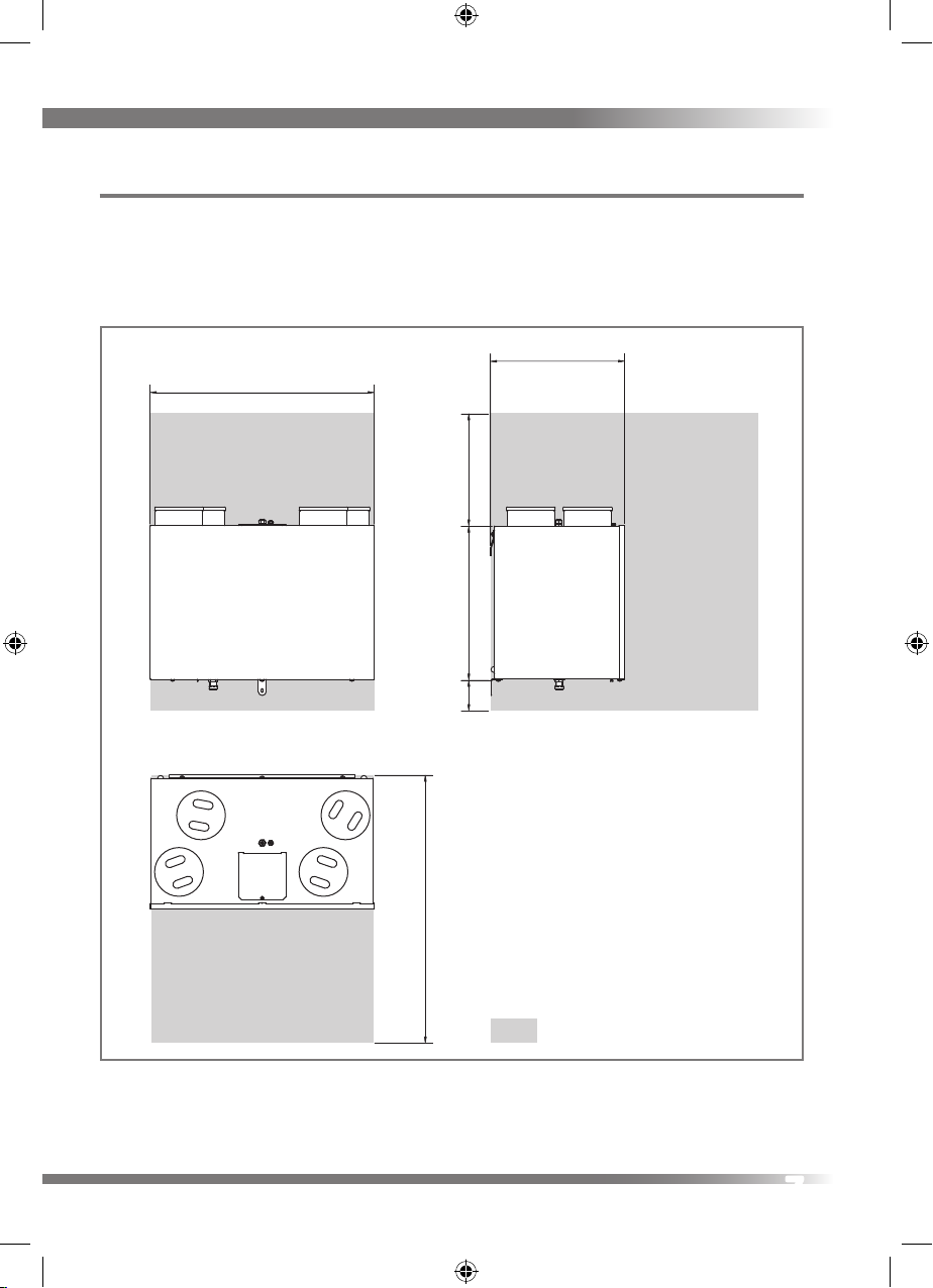
Dimensions HRV1 & 1.25 Q Plus � � � � � � � � � � � � �6
Dimensions HRV1.5, 1.75, 2, 2.75 & 3 Q Plus� � � �7
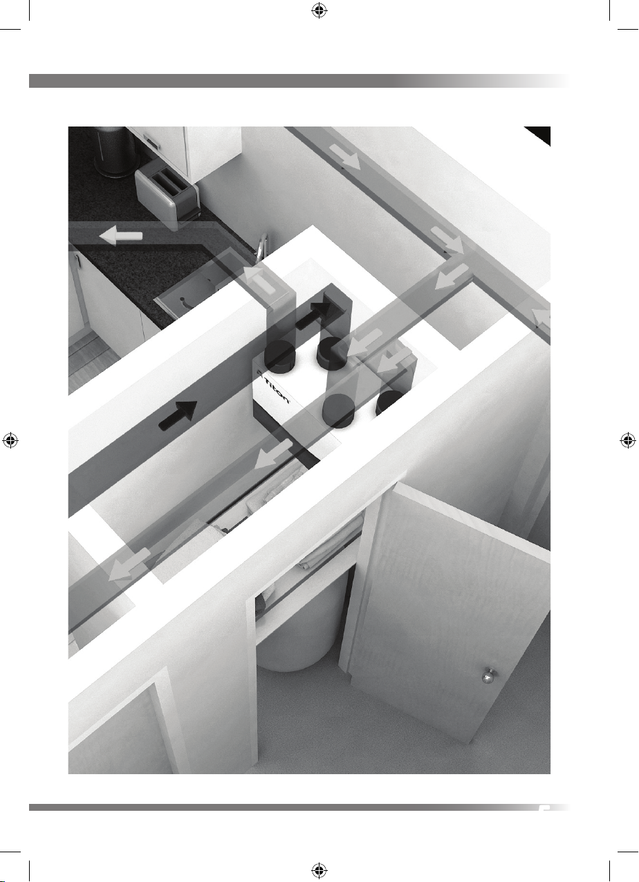
Product Features . . . . . . . . . . . . . . . . . . . . . . . . . . . . .8
Controls & Features . . . . . . . . . . . . . . . . . . . . . . . . . . . 9
Setback Speed . . . . . . . . . . . . . . . . . . . . . . . . . . 9
Boost Speed with Overrun Timer . . . . . . . . . . .9
SUMMERboost® ABS models only . . . . . . . . . .9
Summer Bypass . . . . . . . . . . . . . . . . . . . . . . . .10
Automatic Frost Protection. . . . . . . . . . . . . . .10
Duct Heater. . . . . . . . . . . . . . . . . . . . . . . . . . . .10
Filter Covers . . . . . . . . . . . . . . . . . . . . . . . . . . .10
Constant Volume Fans . . . . . . . . . . . . . . . . . . .10
Packaging Contents. . . . . . . . . . . . . . . . . . . . . . . . . .11
Installation
Fixing . . . . . . . . . . . . . . . . . . . . . . . . . . . . . . . . . . . . .12
Condensate Drain . . . . . . . . . . . . . . . . . . . . . . . . . . .15
Ducting Connections. . . . . . . . . . . . . . . . . . . . . . . . .16
Wiring Connections Access. . . . . . . . . . . . . . . . . . . .18
Wiring Diagrams . . . . . . . . . . . . . . . . . . . . . . .19
Wiring Diagrams . . . . . . . . . . . . . . . . . . . . . . .20
Wiring Diagrams . . . . . . . . . . . . . . . . . . . . . . .21
Wiring Diagrams . . . . . . . . . . . . . . . . . . . . . . .22
Wiring Diagrams . . . . . . . . . . . . . . . . . . . . . . .23
Duct Heater . . . . . . . . . . . . . . . . . . . . . . . . . . . . . . . . 24
Fitting . . . . . . . . . . . . . . . . . . . . . . . . . . . . . . . .25
Connection to Mains . . . . . . . . . . . . . . . . . . . .26
Maintenance. . . . . . . . . . . . . . . . . . . . . . . . . . .27
Overheating . . . . . . . . . . . . . . . . . . . . . . . . . . .27
Commissioning
Controls. . . . . . . . . . . . . . . . . . . . . . . . . . . . . . . . . . . .28
Control Parameters . . . . . . . . . . . . . . . . . . . . . 28
Continuous Supply & Extract Speeds: . . . . . .29
Boost Supply & Extract Speeds: . . . . . . . . . . .29
Boost Overrun. . . . . . . . . . . . . . . . . . . . . . . . . .29
Controller Reset . . . . . . . . . . . . . . . . . . . . . . . .30
Hardware Reset . . . . . . . . . . . . . . . . . . . . . . . .30
Maintenance
Routine Maintenance . . . . . . . . . . . . . . . . . . . . . . . . 31
Front Cover Removal . . . . . . . . . . . . . . . . . . . .31
Cleaning Interior . . . . . . . . . . . . . . . . . . . . . . .32
Cleaning Exterior . . . . . . . . . . . . . . . . . . . . . . .32
Condensate Tray. . . . . . . . . . . . . . . . . . . . . . . . . . . . .32
Filter Replacement . . . . . . . . . . . . . . . . . . . . . . . . . .33
How to Change Filters . . . . . . . . . . . . . . . . . . .34
Service Record . . . . . . . . . . . . . . . . . . . . . . . . . . . . . .35

5

6
Dimensions HRV1 & 1.25 Q Plus
This diagram details the overall size of the unit and the additional space required
around the unit to allow for commissioning and future servicing and maintenance.
430
295
426
490
600
715
600
860
300
100
100
Service Void
Service Void
300
DO NOT
‘BOX-IN’ UNIT
DO NOT
‘BOX-IN’ UNIT
All dimensions in millimetres

7
Dimensions HRV1.5, 1.75, 2, 2.75 & 3 Q Plus
This diagram details the overall sizes of the units and the additional space required
around the units to allow for commissioning and future servicing and maintenance.
430
295
426
490
600
715
600
860
300
100
100
Service Void
Service Void
300
DO NOT
‘BOX-IN’ UNIT
DO NOT
‘BOX-IN’ UNIT
All dimensions in millimetres

8
Product Features
The table below lists the models covered by this Product Manual. To nd out what
features your Titon HRV Q Plus has refer to the part number. The part number can
be found on the serial number label xed to the top and front of the unit.
Model
HRV1 Q Plus
HRV1.25 Q Plus
HRV1.5 Q Plus
HRV1.75 Q Plus
HRV2 Q Plus
HRV2.75 Q Plus
HRV3 Q Plus
Part Number
TP400A
TP406A
TP403A
TP403ABS
TP404A
TP404ABS
TP401A
TP401ABS
TP405A
TP405ABS
TP402A
TP402ABS
Filter Covers l
Setback Speed lllllll
Continuous Speed lllllll
Boost Speed with Overrun Timer lllllll
SUMMERboost® llll l
Summer Bypass lllll
Duct Heater Connection lllll
Summer Mode lllllll
Constant Volume Fans l l
Ø100 & 125mm Ducting l l
Ø125 & 150mm Ducting lllll
Independent adjustment of Fans l l l l l l l
Step-less fan Speed Setting lllllll
Automatic Frost Protection lllllll
GB Patent Nos. GB2469254, GB2470331, GB2470528, GB2470684, & GB2471406
GB Patent Application No. GB2491516,
EP Patent Application No. EP2242959

9
Controls & Features
The HRV Q Plus units are controllable by various volt free switches and sensors.
The following describes the controls and features of the HRV Q Plus units and how
they are controlled. Refer to the table opposite. Ensure all controls are adequately
labelled, indicating their function clearly.
Setback Speed
Setback Speed is used to reduce ventilation rates. Setback Speed is automatically
set at the mid point between minimum possible continuous speed and the selected
continuous speed. The Setback Speed can be enabled by connection of a volt free
one-way switch, or combined with the Boost Speed with the 3 position
switch TP 508.
Boost Speed with Overrun Timer
Boost Speed increases the extract and supply air ow. Boost Speed is congured
with Step-less independent fan controls and includes an Overrun Timer variable
between 0 and 60 minutes. The Boost Speed can be triggered by any device which
provides a volt free one-way switch, such as a PIR, thermostat, humidistat or a
standard one-way switch.
SUMMERboost® ABS models only
An optional SUMMERboost® facility is available that allows both the supply
and extract fans to run at full speed whenever the Summer Bypass is activated.
By default SUMMERboost® is disabled by a Link Wire, see Wiring Diagrams.
Removal of the link wire will enable SUMMERboost®.
When SUMMERboost® is trigged by Summer Bypass the increased fan speed can be
prevented either Manually or Automatically.
Manual - This is by means of a volt-free switch wired directly into the controller PCB.
Automatic - This is by means of a dedicated wall mounted room thermostat.
SUMMERboost® will only operate when the temperature has exceeded the
thermostat setting. Should the room temperature fall below the thermostat setting,
then SUMMERboost® will not operate.

10
Summer Bypass
Summer Bypass is designed to operate during hot periods where fresh air can be
vented straight into the property without being preheated by the extracted stale
air. Summer Bypass operation is automatically controlled. The Summer Bypass
mechanism diverts the stale air being extracted from the dwelling around the heat
cell so that its heat energy is not transferred to the fresh air being supplied to the
property.
Automatic Frost Protection
During very cold weather, Automatic Frost Protection will detect temperatures that
could form ice inside the unit. It will reduce the supply ventilation rate to prevent
ice build up within the heat cell. Automatic Frost Protection reduces the ow rate of
cold air, thus allowing the warmer stale air to raise the temperature within the heat
cell to such a level that prevents the formation of ice. As internal temperatures rise
Automatic Frost Protection will increase the supply ventilation ow rate back to the
commissioned settings.
Duct Heater
To maintain ventilation ow rates where prolonged periods of very low
temperatures occur, the facility for the control of a Duct Heater is provided, MAX
1000W. This is achieved using an electrically powered Duct Heater placed in-line
between the outside supply vent and the From Atmosphere terminal on the HRV
Q Plus. In these applications, the heater is used to pre-warm the outside fresh air
supply before it enters the HRV Q Plus. During Duct Heater operation fan speeds
are not changed. However if the temperatures fall below a predetermined level
Automatic Frost Protection will engage to protect the heat cell.
Filter Covers
Some units are tted with removable lter covers on the front panel.
Constant Volume Fans
These automatically adjust their speed depending upon the system resistance, thus
ensuring that the required airow is always maintained.

11
Summer Mode (A models only)
In properties where it is desirable to reduce the supply of warm fresh air during hot
weather the optional Summer Mode operation is available.
Summer Mode operates by stopping the supply fan. Summer Mode can be
triggered either manually or automatically:
Manual - This is by means of a volt-free switch wired directly into the controller PCB
Automatic - This is by means of a dedicated wall mounted room thermostat. In
this conguration Summer Mode will only operate when the temperature within
the room has exceeded the dedicated thermostat setting. When Summer Mode is
selected the supply fan will remain o even if the HRV10 is placed into Boost.
Summer Mode must not be installed in dwellings where open ue combustion
appliances are used.
Packaging Contents
Inspect the unit when taking delivery. Check the unit for damage and that all
accessories have been supplied. Each HRV Q Plus unit is supplied with:
Mounting Bracket x 2
Safety Bracket x 1
15mm Condensate Drain Olive & Nut x 1
M6x10mm Pan head screws x 4
M6 washers x 4
Transport Bungs x 4, supplied packed in Duct Ports
Product Manual x 1
User Guide x 1
Any shortages or damage must be immediately reported to the supplier.

12
Installation
Fixing
Titon recommend the use of guidance given in the Domestic Ventilation
Compliance Guide 2010 Edition ISBN-978 1 85946 378 9 and Approved Document
Part F 2010 ISBN-978 1 85946 370 3 for all installations in the United Kingdom.
The above documents can be downloaded free from www.
planningportal.gov.uk.
Do not remove the Transport Bungs until connecting ducting. Transport Bungs are
tted to prevent debris falling into the unit and causing blockages and damage:
The Titon HRV Q Plus is designed
to be mounted on a wall or similar.
The mounting surface must be
suciently strong to support the
unit
Consider the positioning of
electrical services and the
Condensate Drain when siting the
unit
Ensure there is sucient access
around the HRV Q Plus for future
maintenance
Do not ‘box-in’ the unit making
access to the unit dicult for maintenance and repair
Transport Bungs highlighted

13
The Unit Must be mounted plumb and level front to back and side to side.
1. Mark a horizontal line on the wall
using a spirit level. This line will be
approximately 95mm below the
location of the top face of the unit
when tted (excluding duct ports)
2. Use one of the Mounting Brackets
as a template to mark the three
xing hole centres
3. Drill holes for xings, always use a
xing suited to the wall type
4. Fix one Mounting Bracket to the
wall ensuring the interlocking side
is at the top, as shown
Mounting Bracket highlighted

14
5. Fix the remaining Mounting
Bracket to the unit using the M6
screws and washers provided,
ensuring the interlock side is at the
bottom. Do not overtighten
6. Mount the unit by locating the
two Mounting Brackets together.
Ensure a positive location is made
between the two Mounting Bracket
7. The Safety Bracket MUST be tted.
Fix the lower Safety Bracket as
shown using the remaining M6
screw, washer and suitable wall
xing. Packing to be used as
required behind the Safety Bracket
to ensure unit is level Hook onto
wall bracket
Safety Bracket highlighted

15
Condensate Drain
The unit’s Condensation Drain Pipe must be tted and connected to the dwelling’s
foul water drainage system in accordance with the relevant building regulations.
The Condensation Drain Pipe:
Is attach via a 15mm compression
tting (drain pipe shown un-
insulated for clarity), on the base of
the unit
Must incorporate a suitable trap,
which must act as an air lock
Must be adequate secured and be
insulated with the equivalent of at
least 25mm of insulating material
with a thermal conductivity of
0.04 W/(mK) if any part of the pipe
passes though an unheated void
Should be installed to have a
minimum 5° fall from the unit
Titon recommend the use of
diaphragm type waste valve in
place of a conventional‘wet’trap
which could dry out. Such as, BRE
certicate no. 042/97‘Hepworth
Hepv0 Hygienic self sealing plastic
waste valve’recommended as an
alternative to traditional U-Traps

16
Ducting Connections
Titon recommend the use of guidance given in the Domestic Ventilation
Compliance Guide 2010 Edition ISBN-978 1 85946 378 9 and Approved Document
Part F 2010 ISBN-978 1 85946 370 3 for all installations in the United Kingdom.
The above documents can be downloaded free from www.
planningportal.gov.uk.
Once the unit has been installed and the ducting is ready to connect to the unit,
remove the Transport Bungs from the Duct Ports.
Titon recommend that:
1. Ø125mm ducting is used to connect the HRV1 & 1.25 Q Plus.
2. Ø150mm ducting is used to connect the HRV1.5, 1.75, 2, 2.75 & 3 Q Plus�
3. A short piece of exible ducting, approximately 200mm long is used to
connect the unit to the ducting system.
4. Any exible ducting used must be pulled taught.
5. A minimum distance of 200mm between the HRV Q Plus unit and any sharp
bends in duct work.
6. Ducting should be insulated where it passes through unheated areas and
voids with the equivalent of at least 25 mm of a material having a thermal
conductivity of ≤0.04 W/(m.K) to reduce the possibility of condensation
forming. Where a duct extends externally above roof level the section above
the roof should be insulated or a condensate trap should be tted just below
roof level.
7. Ducts within the building heated envelope between the external terminals and
the unit’s From Atmosphere and To Atmosphere ports should be insulated and
wrapped additionally with a vapour barrier outside the insulation.
8. Where ducts pass through re barriers, they must be appropriately re stopped
in accordance with the requirements of Part B of the Building Regulations (for
England & Wales).

17
9. A ducting condensate drain must be tted to vertical To Atmosphere duct
work.
10. Ducting must be installed in such a way that resistance to airow is minimised.
11. Ducting connected to the From Atmosphere & To Atmosphere ports, must be
to the external air outside the building envelope.
12. All ducting joints including those to the HRV Q Plus unit’s Duct Ports must be
permanently sealed with tape and/or an appropriate non-hardening sealant
and/or Jubilee clips or similar. Do not distort ducting or Duct Ports by over
tightening clips.
13. A minimum distance of 2m exists between the external supply and exhaust
terminals.
The HRV unit has a label on the top with the icons indicating which port is which.
It is very important that ducting is connected to the correct ports in line with
the icons below.
EXTRACT FROM DWELLING - This duct port is connected to the ducting that
carries waste air from the‘Wet Rooms’to the HRV unit.
TO ATMOSPHERE - This duct port is connected to the ducting that carries
the waste air to outdoors from the HRV unit.
SUPPLY TO DWELLING - This duct port is connected to the ducting that
carries the fresh warmed air to the habitable rooms from the HRV unit.
FROM ATMOSPHERE - This duct port is connected to the ducting that
carries fresh outdoor air to the HRV unit.

18
Wiring Connections Access
Access to the connections for Boost and other volt free control functions is via the
hinged cover on the top of the unit, at the front. All units.
Access to the connections for the duct heater is via the cover xed by four screws on
top of the unit, at the rear of ABS units.

19
Wiring Diagrams
Double Pole Isolator Fuse
L
N
L
N
Supply wiring diagram 230V~50Hz ref EE 141
Volt-free boost switching of MVHR
controller PCB using single-pole
switches TP 502, TP 503, TP 507
and / or TP500 / TP501 humidistat.
There is no limit to the number of
single pole switches or
humidistats that can used.
SWITCH POSITIONS
1 - Setback Speed
2 - Continous Speed
3 - Boost Speed
Volt-free setback switching of MVHR
controller PCB using single-pole
latching switch and / or volt-free
normally open relay contacts.
To avoid the unit being inadvertently
left in Setback Mode, it is recom-
mended that only one latching switch
is tted.
Volt-free disable of SUMMERboost®
using one way latching switch.
ABS models only.
L U1 U2 U3
TP 508
Three position rotary switch
Volt-free disable of SUMMERboost®
using room thermostat.
ABS models only.
TP500/TP501
Humidistat
12 3
Volt-free setback switch or
normally open relay contacts
BP 40262/099
Thermostat
Switch
Boost
Switch
Setback
Switch
Input
Temp
BoostCont
TP 522
Latching SUMMERboost® switch
TP509
Room Thermostat
BP 40262/099
Thermostat
Switch
Boost
Switch
Setback
Switch
Input
Temp
BoostCont
BP 40262/099
Thermostat
Switch
Boost
Switch
Setback
Switch
Input
Temp
BoostCont
BP 40262/099
Thermostat
Switch
Boost
Switch
Setback
Switch
Input
Temp
BoostCont
BP 40262/099
Thermostat
Switch
Boost
Switch
Setback
Switch
Input
Temp
BoostCont
Y1
L
Y2
Volt-free activation of Summer Mode
using one way latching switch.
Not to be installed
on ABD & ABS models.
Volt-free activation of Summer Mode
using room thermostat.
Not to be installed
on ABD & ABS models.
TP 506
Latching Summer Mode
switch
TP509
Room Thermostat
BP 40262/099
Thermostat
Switch
Boost
Switch
Setback
Switch
Input
Temp
BoostCont
BP 40262/099
Thermostat
Switch
Boost
Switch
Setback
Switch
Input
Temp
BoostCont
Y1
L
Y2
Boost switching and Humidistat connection ref EE 142

20
Wiring Diagrams
Volt-free boost switching of MVHR
controller PCB using single-pole
switches TP 502, TP 503, TP 507
and / or TP500 / TP501 humidistat.
There is no limit to the number of
single pole switches or
humidistats that can used.
SWITCH POSITIONS
1 - Setback Speed
2 - Continous Speed
3 - Boost Speed
Volt-free setback switching of MVHR
controller PCB using single-pole
latching switch and / or volt-free
normally open relay contacts.
To avoid the unit being inadvertently
left in Setback Mode, it is recom-
mended that only one latching switch
is tted.
Volt-free disable of SUMMERboost®
using one way latching switch.
ABS models only.
L U1 U2 U3
TP 508
Three position rotary switch
Volt-free disable of SUMMERboost®
using room thermostat.
ABS models only.
TP500/TP501
Humidistat
12 3
Volt-free setback switch or
normally open relay contacts
BP 40262/099
Thermostat
Switch
Boost
Switch
Setback
Switch
Input
Temp
BoostCont
TP 522
Latching SUMMERboost® switch
TP509
Room Thermostat
BP 40262/099
Thermostat
Switch
Boost
Switch
Setback
Switch
Input
Temp
BoostCont
BP 40262/099
Thermostat
Switch
Boost
Switch
Setback
Switch
Input
Temp
BoostCont
BP 40262/099
Thermostat
Switch
Boost
Switch
Setback
Switch
Input
Temp
BoostCont
BP 40262/099
Thermostat
Switch
Boost
Switch
Setback
Switch
Input
Temp
BoostCont
Y1
L
Y2
Volt-free activation of Summer Mode
using one way latching switch.
Not to be installed
on ABS models.
Volt-free activation of Summer Mode
using room thermostat.
Not to be installed
on ABS models.
TP 506
Latching Summer Mode
switch
TP509
Room Thermostat
BP 40262/099
Thermostat
Switch
Boost
Switch
Setback
Switch
Input
Temp
BoostCont
BP 40262/099
Thermostat
Switch
Boost
Switch
Setback
Switch
Input
Temp
BoostCont
Y1
L
Y2
Summer Mode switch connection ref EE 144
Summer Mode thermostat connection ref EE 144
Volt-free boost switching of MVHR
controller PCB using single-pole
switches TP 502, TP 503, TP 507
and / or TP500 / TP501 humidistat.
There is no limit to the number of
single pole switches or
humidistats that can used.
SWITCH POSITIONS
1 - Setback Speed
2 - Continous Speed
3 - Boost Speed
Volt-free setback switching of MVHR
controller PCB using single-pole
latching switch and / or volt-free
normally open relay contacts.
To avoid the unit being inadvertently
left in Setback Mode, it is recom-
mended that only one latching switch
is tted.
Volt-free disable of SUMMERboost®
using one way latching switch.
ABS models only.
L U1 U2 U3
TP 508
Three position rotary switch
Volt-free disable of SUMMERboost®
using room thermostat.
ABS models only.
TP500/TP501
Humidistat
12 3
Volt-free setback switch or
normally open relay contacts
BP 40262/099
Thermostat
Switch
Boost
Switch
Setback
Switch
Input
Temp
BoostCont
TP 522
Latching SUMMERboost® switch
TP509
Room Thermostat
BP 40262/099
Thermostat
Switch
Boost
Switch
Setback
Switch
Input
Temp
BoostCont
BP 40262/099
Thermostat
Switch
Boost
Switch
Setback
Switch
Input
Temp
BoostCont
BP 40262/099
Thermostat
Switch
Boost
Switch
Setback
Switch
Input
Temp
BoostCont
BP 40262/099
Thermostat
Switch
Boost
Switch
Setback
Switch
Input
Temp
BoostCont
Y1
L
Y2
Volt-free activation of Summer Mode
using one way latching switch.
Not to be installed
on ABS models.
Volt-free activation of Summer Mode
using room thermostat.
Not to be installed
on ABS models.
TP 506
Latching Summer Mode
switch
TP509
Room Thermostat
BP 40262/099
Thermostat
Switch
Boost
Switch
Setback
Switch
Input
Temp
BoostCont
BP 40262/099
Thermostat
Switch
Boost
Switch
Setback
Switch
Input
Temp
BoostCont
Y1
L
Y2
This manual suits for next models
18
Table of contents
Other Titon Heating System manuals