TL Ultralight Sting TL-2000 2009 Owner's manual
Pilot Operating Handbook Section 0
TL-2000 Sting Introduction
Notice! The information contained in this document is for reference and information only.
The pilot is the final and only responsible party for the safe operation of this aircraft.
31 December 2009 / Change 5 Copyright © 2009
Reproduction of this document or any of its parts is forbidden.
This Pilot Operating Handbook must remain in the aircraft and be accessible to the pilot all times.

Pilot Operating Handbook Section 0
TL-2000 Sting Introduction
Notice! The information contained in this document is for reference and information only.
The pilot is the final and only responsible party for the safe operation of this aircraft.
(THIS PAGE BLANK)

Pilot Operating Handbook Section 0
TL-2000 Sting Introduction
Notice! The information contained in this document is for reference and information only.
The pilot is the final and only responsible party for the safe operation of this aircraft.
31 December 09 / Chg 5 i
Copyright © 2009 Reproduction of this document or any of its parts is forbidden
Dear Sting Owner:
Congratulations on the purchase of your Sting! You will find your new TL
Ultralight aircraft very enjoyable, extremely economical, and easy to maintain.
The Sting is the ideal Light Sport Airplane. It is fast, economical, pleasing to the
eye, and user friendly. We at TL Aircraft are certain that your Sting will give you
hours and hours of leisure flying and enjoyment. With this Pilot Operating
Handbook (POH), we hope to help inform you about the design and operation of
your aircraft.
This Pilot Operating Handbook is to be used as a guide to assist the pilot to safely
use the Sting aircraft. The contents are not intended to be a final authority and
although proofed extensively they are still not considered error free. Therefore, the
pilot in command is the final authority for the safe operation of the aircraft. Should
there be any questions or errors found in your reading this handbook please contact
us immediately and we will issue a clarification.
Thank you again for your business. We look forward to a continuing satisfied
customer relationship. Feel free to contact us if you have any questions or
comments regarding your Sting aircraft.
Fly safe! Fly fun!
(sig)
Jiri Tlusty
TL Ultralight, sro
Letištĕ, Budova c.84
509 41 Hradec Králové
Czech Republic

Pilot Operating Handbook Section 0
TL-2000 Sting Introduction
Notice! The information contained in this document is for reference and information only.
The pilot is the final and only responsible party for the safe operation of this aircraft.
31 December 09 / Chg 5 ii
Copyright © 2009 Reproduction of this document or any of its parts is forbidden
(THIS PAGE BLANK)
Pilot Operating Handbook Section 0
TL-2000 Sting Introduction
Notice! The information contained in this document is for reference and information only.
The pilot is the final and only responsible party for the safe operation of this aircraft.
31 December 09 / Chg 5 iii
Copyright © 2009 Reproduction of this document or any of its parts is forbidden
SECTION INDEX
SECTION
GENERAL ........................................................................ 1
OPERATING LIMITATIONS ............................................ 2
EMERGENCY PROCEDURES ........................................ 3
NORMAL PROCEDURES ............................................... 4
PERFORMANCE ............................................................. 5
WEIGHT AND BALANCE INFORMATION ...................... 6
AIRPLANE & SYSTEMS DESCRIPTIONS ...................... 7
REQUIRED PLACARDS & MARKINGS .......................... 8
AIRPLANE SERVICE, HANDLING, & MAINTENANCE .. 9
SUPPLEMENTARY INFORMATION……………………...10

Pilot Operating Handbook Section 0
TL-2000 Sting Introduction
Notice! The information contained in this document is for reference and information only.
The pilot is the final and only responsible party for the safe operation of this aircraft.
31 December 09 / Chg 5 iv
Copyright © 2009 Reproduction of this document or any of its parts is forbidden
NOTES, CAUTIONS, AND WARNINGS
Every owner, pilot, operator, or user of the Sting should become familiar with the
entire text of this POH. The text consists of flight, systems operation and
maintenance information and is required to be on board the plane and available
to the pilot during all flights.
Throughout this manual, small boxes are inserted referencing a Note, Caution,
or Warning. These are items which require particularly close attention for
special conditions or procedures.
This text box emphasizes specific operating conditions, steps in a
procedure, helpful hints or useful advice.
This text box represents danger to equipment or operation. By not
observing the cautions, the result could be the destruction of
equipment and possibly personal danger and injury.
This text box represents a hazardous situation. Warnings are
used to call attention to operating procedures or conditions
which, if not strictly observed, may result in personal injury or
death.
The authority of TL Ultralight, as the original equipment manufacturer (OEM), is
complete and final for all operation or maintenance of the aircraft and aircraft
components. This document also incorporates some references from Rotax®, the
engine supplier, Woodcomp®, the propeller supplier, and Galaxy®, the installed
aircraft parachute system. Please refer to the latest edition of those manufacturer
manuals for specific and complete detailed operation of each aircraft system.
However, final authority over the aircraft, continued safety operation, maintenance
for the aircraft and all aircraft components rests with the OEM.
NOTE
CAUTION
WARNING

Pilot Operating Handbook Section 0
TL-2000 Sting Introduction
Notice! The information contained in this document is for reference and information only.
The pilot is the final and only responsible party for the safe operation of this aircraft.
31 December 09 / Chg 5 v
Copyright © 2009 Reproduction of this document or any of its parts is forbidden
The Sting is intended for sport and recreational purposes
only. This aircraft meets the standard specification Design
and Performance (D&P) established by ASTM Document F
2245, and it is therefore restricted by that guideline. The
aircraft does not comply with any FAA Part 22, or 23
certification processes. Compliance with regulations placed
upon the airplane category should be strictly adhered to by
the operator or pilot in command (PIC)
Each aircraft is issued an FAA form 8050-15, which is
a statement identifying the specific ASTM standard
used in design and manufacture of that seral aircraft.
The items discussed in each amplified procedures are
informational. None of these items or procedures are
intended to replace properly qualified ground or in-flight
instruction by an FAA certified flight instructor (CFI).
This POH manual is valid only with any changes that may be
issued at a later date. Any pages affected by a change should
be removed and replaced with the effective pages
immediately.
If this manual is found not to be current, revisions missing, or
pages removed contact our USA Continued Airworthiness
Service location in accordance with ASTM for replacements.
TL Ultralight, s.r.o.
USA Continued Airworthiness Service
8222 Remount Road
North Little Rock, AR 72118
Phone: 501.228.7777
Fax: 501.227.8888
CAUTION
CAUTION
NOTE

Pilot Operating Handbook Section 0
TL-2000 Sting Introduction
Notice! The information contained in this document is for reference and information only.
The pilot is the final and only responsible party for the safe operation of this aircraft.
31 December 09 / Chg 5 ____________________vii
Copyright © 2009 Reproduction of this document or any of its parts is forbidden.
LIST OF EFFECTIVE PAGES
Page No.............. Date
Cover .............. 12-31-09
i ....................... 12-31-09
ii ...................... 12-31-09
iii ..................... 12-31-09
iv ..................... 12-31-09
v ...................... 12-31-09
vi ..................... 12-31-09
vii .................... 12-31-09
viii (blank) ........ 12-31-09
1-1 ................... 12-31-09
1-2(blank) ........ 12-31-09
1-3 ................... 12-31-09
1-4 ................... 12-31-09
1-5 ................... 12-31-09
1-6 ................... 12-31-09
1-7 ................... 12-31-09
1-8 ................... 12-31-09
1-9 ................... 12-31-09
1-10 ................. 12-31-09
1-11 ................. 12-31-09
1-12 ................. 12-31-09
1-13 ................. 12-31-09
1-14 ................. 12-31-09
1-15 ................. 12-31-09
1-16(blank) ...... 12-31-09
2-1 ................... 12-31-09
2-2 (blank) ....... 12-31-09
2-3 ................... 12-31-09
2-4 ................... 12-31-09
2-5 ................... 12-31-09
2-6 ................... 12-31-09
2-7 ................... 12-31-09
2-8 ................... 12-31-09
3-1 ................... 12-31-09
3-2 (blank) ....... 12-31-09
3-3 ................... 12-31-09
3-4 ................... 12-31-09
3-5 ................... 12-31-09
3-6 ................... 12-31-09
3-7 ................... 12-31-09
3-8 ................... 12-31-09
3-9 ................... 12-31-09
3-10 ................. 12-31-09
3-11 ................. 12-31-09
3-12 ................. 12-31-09
3-13 ................. 12-31-09
3-14 ................. 12-31-09
3-15 ................. 12-31-09
3-16 ................. 12-31-09
3-17 ................. 12-31-09
3-18 ................. 12-31-09
3-19 ................. 12-31-09
3-20 ................. 12-31-09
4-1 ................... 12-31-09
4-2 (blank) ....... 12-31-09
4-3 ................... 12-31-09
4-4 ................... 12-31-09
4-5 ................... 12-31-09
4-6 ................... 12-31-09
4-7 ................... 12-31-09
4-8 ................... 12-31-09
4-9 ................... 12-31-09
4-10 ................. 12-31-09
4-11 ................. 12-31-09
4-12 ................. 12-31-09
4-13 ................. 12-31-09
4-14 ................. 12-31-09
4-15 ................. 12-31-09
4-16 ................. 12-31-09
4-17 ................. 12-31-09
4-18 ................. 12-31-09
4-19 ................. 12-31-09
4-20 ................. 12-31-09
4-21 ................. 12-31-09
4-22 ................. 12-31-09
4-23 ................. 12-31-09
4-24 ................. 12-31-09
5-1 ................... 12-31-09
5-2 (blank) ....... 12-31-09
5-3 ................... 12-31-09
5-4 (blank) ....... 12-31-09
6-1 ................... 12-31-09
6-2 (blank) ....... 12-31-09
6-3 ................... 12-31-09
6-4 ................... 12-31-09
6-5 ................... 12-31-09
6-6 ................... 12-31-09
6-7 ................... 12-31-09
6-8 ................... 12-31-09
6-9 ................... 12-31-09
6-10 ................. 12-31-09
6-11 ................. 12-31-09
6-12 ................. 12-31-09
6-13 ................. 12-31-09
6-14 (blank) ..... 12-31-09
7-1 ................... 12-31-09
7-2 (blank) ....... 12-31-09
7-3 ................... 12-31-09
7-4 ................... 12-31-09
7-5 ................... 12-31-09
7-6 ................... 12-31-09
7-7 ................... 12-31-09
7-8 ................... 12-31-09
7-9 ................... 12-31-09
7-10 ................. 12-31-09
7-11 ................. 12-31-09
7-12 ................. 12-31-09
7-13 ................. 12-31-09
7-14 ................. 12-31-09
7-15 ................. 12-31-09
7-16 ................. 12-31-09
7-17 ................. 12-31-09
7-18 ................. 12-31-09
7-19 ................. 12-31-09
7-20(blank) ...... 12-31-09
8-1 ................... 12-31-09
8-2 (blank) ....... 12-31-09
8-3 ................... 12-31-09
8-4 ................... 12-31-09
8-5 ................... 12-31-09
8-6 ................... 12-31-09
9-1 ................... 12-31-09
9-2 (blank) ....... 12-31-09
9-3 ................... 12-31-09
9-4 ................... 12-31-09
9-5 ................... 12-31-09
9-6 ................... 12-31-09
9-7 ................... 12-31-09
9-8 ................... 12-31-09
9-9 ................... 12-31-09
9-10 ................. 12-31-09
9-11 ................. 12-31-09
9-12 ................. 12-31-09
10-1 ................. 12-31-09
10-2 (blank) ..... 12-31-09
10-3 ................. 12-31-09
10-4 (blank) ..... 12-31-09
10-6 ................. 12-31-09
10-7 ................. 12-31-09
10-8 ................. 12-31-09
10-9 ................. 12-31-09
10-10(blank) .... 12-31-09
10-11 ............... 12-31-09
10-12 ............... 12-31-09
10-13 ............... 12-31-09
10-14 ............... 12-31-09
10-15 ............... 12-31-09
10-16 ............... 12-31-09
10-17 ............... 12-31-09
10-18 ............... 12-31-09
10-19 ............... 12-31-09
10-20 ............... 12-31-094-
10-21 ............... 12-31-09
10-22(blank) .... 12-31-09
Pilot Operating Handbook Section 0
TL-2000 Sting Introduction
Notice! The information contained in this document is for reference and information only.
The pilot is the final and only responsible party for the safe operation of this aircraft.
31 December 09 / Chg 5 ____________________vii
Copyright © 2009 Reproduction of this document or any of its parts is forbidden.
List of changes
CHG
NR
REVISED
DATE
REVISED
PAGES
EXTENT OF
REVISION
CHANGE
POSTED
0
1 May 2005
None
Original Issue
N/A
1
31 Dec 2005
All
Re-issue All Pages
N/A
2
31 Mar 2009
All
Re-issue All Pages
N/A
3
31 Jun 2009
4
Errata
N/A
4
31 Sep 2009
All
All pages and Errata
N/A
5
31 Dec 2009
All
All pages and Errata

Pilot Operating Handbook Section 0
TL-2000 Sting Introduction
Notice! The information contained in this document is for reference and information only.
The pilot is the final and only responsible party for the safe operation of this aircraft.
31 December 09 / Chg 5 ____________________viii
Copyright © 2009 Reproduction of this document or any of its parts is forbidden.
(This Page Blank.)
Pilot Operating Handbook Section 1
TL-2000 Sting General
Notice! The information contained in this document is for reference and information only.
The pilot is the final and only responsible party for the safe operation of this aircraft.
31 December 09 / Chg 5 1-1
Copyright © 2009 Reproduction of this document or any of its parts is forbidden.
SECTION 1
GENERAL INFORMATION
TABLE OF CONTENTS
Page
THREE VIEW DRAWINGS (Sting S3) ............................................................. 1-2
THREE VIEW DRAWINGS (Sting Sport) ........................................................ 1-3
INTRODUCTION ............................................................................................... 1-4
DESCRIPTIVE DATA ....................................................................................... 1-4
AIRCRAFT ........................................................................................................ 1-4
AIRPLANE WEIGHTS ...................................................................................... 1-5
ENGINE ............................................................................................................ 1-5
PROPELLER .................................................................................................... 1-5
PARACHUTE SYSTEM .................................................................................... 1-6
FUEL ................................................................................................................. 1-6
OIL .................................................................................................................... 1-7
SYMBOLS, ABBREVIATIONS, AND TERMINOLOGY .................................... 1-8
GENERAL AIRSPEED TERMINOLOGY .......................................................... 1-8
METEORLOGICAL TERMINOLOGY ............................................................... 1-9
AIRPLANE PERFORMANCE AND WEIGHT TERMINOLOGY ..................... 1-10
ABBREVIATIONS .......................................................................................... 1-13

Pilot Operating Handbook Section 1
TL-2000 Sting General
Notice! The information contained in this document is for reference and information only.
The pilot is the final and only responsible party for the safe operation of this aircraft.
31 December 09 / Chg 5 1-2
Copyright © 2009 Reproduction of this document or any of its parts is forbidden.
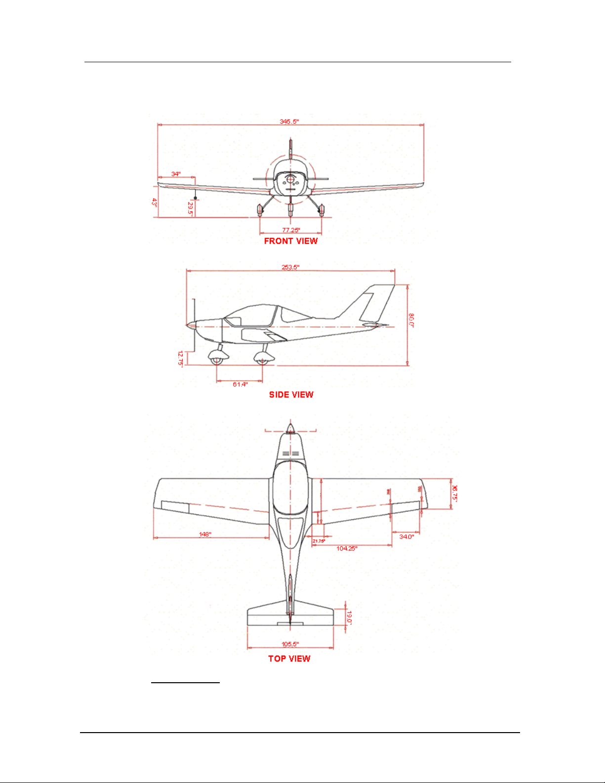
Three View Drawings
Sting S3
Pilot Operating Handbook Section 1
TL-2000 Sting General
Notice! The information contained in this document is for reference and information only.
The pilot is the final and only responsible party for the safe operation of this aircraft.
31 December 09 / Chg 5 1-3
Copyright © 2009 Reproduction of this document or any of its parts is forbidden.
Three View Drawings
Sting Sport_______________________________

Pilot Operating Handbook Section 1
TL-2000 Sting General
Notice! The information contained in this document is for reference and information only.
The pilot is the final and only responsible party for the safe operation of this aircraft.
31 December 09 / Chg 5 1-4
Copyright © 2009 Reproduction of this document or any of its parts is forbidden.
INTRODUCTION
This manual is written and organized to conform to the ASTM F2245, Design and
Performance of a Light Sport Aircraft. A copy is issued with each aircraft and is
required to remain in the aircraft and be available to the pilot at all times.
All pilots of this aircraft must read and understand the operation and limitations of
this aircraft design. As such, many items are added as narrative information to
assist them in clearly understanding what is required and in most cases help in
achieving the necessary performance. The POH does not intend to and cannot
replace properly qualified ground or in-flight instruction by an FAA certified flight
instructor. (CFI)
Maintenance and operation of major components, engine, aircraft parachute
system, propeller, avionics or other installed equipment is provided in the
appropriate component supplier manuals which are included with the aircraft. Any
conflicts found in these supplier manuals are superseded by the appropriate OEM
manufacturer’s POH or AMM manuals.
The Sting is has a high cruising speed and may traverse very different weather
conditions during a single flight. The aircraft is designed and intended only for
operation in VFR/VMC conditions. The pilot is responsible for the safe flight of the
aircraft and should be prepared to avoid any meteorological conditions which will
endanger the occupants, the aircraft or both.
Section 1 provides general information and descriptive figures relevant to the
aircraft and the engine. It also contains certain definitions of aeronautical terms,
ASTM Design and Performance standards and commonly used abbreviations.
DESCRIPTIVE DATA
AIRCRAFT
The TL-2000 Sting is a full three axis, low wing, two place, side-by-side seating,
tricycle landing gear aircraft with a steerable nose wheel. The primary aircraft
structure is carbon fiber and fiberglass UV resistant reinforced laminate with an
inner foam core creating a ‘sandwich’ layered construction between each ply.
Various options may also be installed such as tinted canopies, wing fuel tanks,
avionics or interior selections. Therefore, your aircraft may vary from the
descriptions in this manual. Please check with the TL USA Continuing
Airworthiness Center if you have any specific questions not addressed here.
Pilot Operating Handbook Section 1
TL-2000 Sting General
Notice! The information contained in this document is for reference and information only.
The pilot is the final and only responsible party for the safe operation of this aircraft.
31 December 09 / Chg 5 1-5
Copyright © 2009 Reproduction of this document or any of its parts is forbidden.
BASIC DIMENSIONS
Length .......................................................................... 20.33 ft.
Cabin width .................................................................. 44 in.
Wingspan - Sport - (S3) ................................................ 28.2 ft. - (29.3 ft.)
Height .......................................................................... 78 in.
Areas
Wing ............................................................................. 121.4 ft2
Flap .............................................................................. 18.6 ft2
Aspect ratio .................................................................. 7.26
Glide ratio ..................................................................... 12:1
AIRPLANE WEIGHTS
Maximum Calculated Structural Weight: 1430 Lbs
Maximum Ramp Weight: 1340 Lbs
Maximum Takeoff or Landing Weight: 1320 Lbs
Standard Empty Weight: 780 Lbs
Maximum Useful Load: 540 Lbs
Total Baggage Weight: 60 Lbs.
Each baggage compartment can hold a maximum of 20
Lbs. An additional 20 Lbs may be loaded on the surface
of deck aft of the seats if properly secured against an
abrupt movement. Total baggage limit is 60 lbs (20-20-
20).
ENGINE
Number of Engines: 1
Engine Manufacturer: Rotax® G.m.b.H. Aircraft Engines
Engine Model Number: 912 UL(S), Standard Equipment
Engine Type: Normally-aspirated, liquid/air-cooled, dry sump, gear-reduced drive,
dual carburetor-equipped, four-cylinder, four-stroke, electronic dual
ignition, horizontally-opposed engine.
Horsepower Rating and Engine Speed: 80(100) BHP at 5800 RPM
PROPELLER
Propeller Manufacturer: Woodcomp® Propellers, SRO
Propeller Model Number: SR 200
NOTE

Pilot Operating Handbook Section 1
TL-2000 Sting General
Notice! The information contained in this document is for reference and information only.
The pilot is the final and only responsible party for the safe operation of this aircraft.
31 December 09 / Chg 5 1-6
Copyright © 2009 Reproduction of this document or any of its parts is forbidden.
Number of Blades: 3
Propeller Diameter: 63 In
Propeller Type: Fixed-pitch, ground-adjustable
Blade Pitch: Standard Conditions
Lowest Possible Angle Setting: 16°
Best Climb Angle Setting: 17°
Maximum Cruise Setting: 21.5°
Highest possible Angle Setting: 26°
Adjusting the propeller blades at a higher setting than 21.5°, in
an attempt to obtain a higher cruise speed, may cause the
engine RPM to “bog-down”, fail to reach a sufficient ground
RPM, and may not allow a safe takeoff.
Loading the engine with a high propeller pitch angle (high
propeller ‘angle of attack’ (AOA) or ‘big angle’) above 21.5° may
also result in may result in extremely long takeoff rolls and low
climb rates.
High propeller pitch angles will result in high engine CHT
temperatures during climb and may also result in additional
engine vibration due to minor differences in the pitch of each
blade.
GALAXY ROCKET PARACHUTE SYSTEM
The rocket deployed aircraft parachute system is standard equipment. It is
activated inside the cockpit by pulling a red “T” handle located on the overhead roll
bar above and between the crew positions. The system is secured by an
embroidered red safety tag attached to a brass safety pin. Refer to the Galaxy
operational manual included with the aircraft for detailed information.
FUEL
Approved Fuel Grade:
91 Unleaded Automobile Fuel, “Auto gas” (Yellow)
Alternate Fuel Grade:
100LL Aviation Fuel, “Avgas” (Blue)
WARNING
NOTE

Pilot Operating Handbook Section 1
TL-2000 Sting General
Notice! The information contained in this document is for reference and information only.
The pilot is the final and only responsible party for the safe operation of this aircraft.
31 December 09 / Chg 5 1-7
Copyright © 2009 Reproduction of this document or any of its parts is forbidden.
100LL Avgas is an alternate fuel type if 91 octane unleaded auto
fuel is not available. Due to the high lead content, the use of 100LL
Avgas is restricted to less than 33% of engine time without
increased engine maintenance. See the latest Rotax engine
operational supplement for more detailed fuel specifications and
information.
Total Fuel Capacity: 20.5 US Gallons (Useable)
Total Wing Tank Capacity: 12.0 US Gallons (Useable)
During refueling, the main fuel tank can be filled with approximately
21.5 gallons of fuel. This will eliminate all fuel expansion area as the
fuel expands it will be forced out of the fuel vent line and spill on to
the parking area causing a fire hazard..
Total Unusable Fuel: Main tank: US 1.0 Gallons
Wing tank(s) (if installed): US .25 Gallons each
During ground operation fuel level indication will be higher than in-
flight due to changes in pitch attitude.
Total unusable fuel is the minimum amount of fuel an aircraft may
have in its gas tank before engine fuel starvation. Unusable fuel, as
its name implies, cannot be consumed by the engine for power and
thus cannot be relied upon for flight, but is included in the aircraft
empty weight.
OIL
Oil Capacity: 3.7 Quarts (Includes oil trapped in engine & cooler)
Oil Filter: Rotax part number 825 701.
Rotax Oil Filter: part number 825 701 must be used, no
substitutions allowed. The engine oil pressure may cause
the oil to bypass the oil filter if a non-approved filter is used.
CAUTION
CAUTION
NOTE

Pilot Operating Handbook Section 1
TL-2000 Sting General
Notice! The information contained in this document is for reference and information only.
The pilot is the final and only responsible party for the safe operation of this aircraft.
31 December 09 / Chg 5 1-8
Copyright © 2009 Reproduction of this document or any of its parts is forbidden.
Oil Specifications: Vary depending on the engine operation and may vary from one
aircraft to another depending on the operation, environment and fuel type. Refer to
latest Rotax engine oil service instructions for current specifications!
BAGGAGE
Baggage is stored behind the seats in two separate containers. Each baggage
compartment can hold a maximum of 20 Lbs. An additional 20 Lbs may be
loaded on the surface of deck aft of the seats if properly secured against an
abrupt movement.
Do not allow baggage to block the exit area of the aircraft
parachute system nor hinder free deployment of the parachute
riser cables. After securing baggage, assure that each
shoulder harness is free to move and operational.
SYMBOLS, ABBREVIATIONS, AND TERMINOLOGY
GENERAL AIRSPEED TERMINOLOGY
Best Angle-of-Climb Speed (VX): The speed which results in the greatest gain of
altitude in a given horizontal distance.
Best Rate-of-Climb Speed (VY): The speed which results in the greatest gain in
altitude in a given time.
Best Glide Speed (VG): The speed that will result in maximum glide distance.
Design Cruise Speed (VC): The optimal cruise speed.
Knots Calibrated Airspeed (KCAS): Indicated airspeed corrected for position and
instrument error and expressed in knots. KCAS is equal to KTAS in standard
conditions at sea level.
Knots Indicated Airspeed (KIAS): The speed shown on the airspeed indicator
and is expressed in knots. (Decreases approximately 2kt/1000’ of ALT.)
WARNING

Pilot Operating Handbook Section 1
TL-2000 Sting General
Notice! The information contained in this document is for reference and information only.
The pilot is the final and only responsible party for the safe operation of this aircraft.
31 December 09 / Chg 5 1-9
Copyright © 2009 Reproduction of this document or any of its parts is forbidden.
Knots True Airspeed (KTAS): KCAS corrected for non-standard temperature and
pressure and is expressed in knots.
Maneuvering Speed (VA): The maximum speed at which you may use abrupt full
control travel without exceeding structural limitations of the aircraft or control
systems.
Maximum Flap Extended Speed (VFE): The highest speed permissible with wing
flaps in a prescribed extended position.
Maximum Structural Cruising Speed (VNO): The speed that should not be
exceeded except in smooth air, and then only with caution.
Maximum Sustained Speed in Level Flight (VH): The highest speed that can be
attained in level flight at sea level under standard conditions while the engine is
operating at the manufacturer designated maximum continuous power setting.
Never Exceed Speed (VNE): The speed limit that may never be exceeded under
any conditions at any time due to structural limitations of the airframe or control
systems.
Stalling Speed (VS): The minimum steady flight speed at which the airplane is
controllable without flaps.
Stalling Speed (VS0): The minimum steady flight speed with power off and full
flaps.
METEORLOGICAL TERMINOLOGY
Indicated Altitude: The altitude displayed on the altimeter.
Mean Sea Level (MSL): The average level of the ocean’s surface – the level
halfway between mean high and low tides, used as a standard reference for
expressing altitude.
Outside Air Temperature (OAT): The free air static temperature, expressed in
either degrees Celsius (C) or degrees Fahrenheit (F).
Pressure Altitude: The altitude displayed on the altimeter on a standard day when
the altimeter's barometric scale has been set to 29.91 inches of mercury (1013 mb).
Pilot Operating Handbook Section 1
TL-2000 Sting General
Notice! The information contained in this document is for reference and information only.
The pilot is the final and only responsible party for the safe operation of this aircraft.
31 December 09 / Chg 5 1-10
Copyright © 2009 Reproduction of this document or any of its parts is forbidden.
Standard Temperature: 15°C at sea level pressure altitude. (Decreases
approximately 2°C for each 1000 feet increase of altitude.)
True Altitude: The true height above mean sea level (MSL). True altitude is
indicated altitude corrected for nonstandard atmospheric pressure.
AIRPLANE PERFORMANCE AND WEIGHT TERMINOLOGY
Arm: The horizontal distance expressed in inches from the reference datum plane
to the center of gravity (CG) of an item or location.
Units of measurements and weights must be consistent for each set
of calculations and in the same system of units, i.e., pounds and
inches, or kilograms and centimeters.
Auto Gas – Automobile fuel, 91 Octane is min auto gas rating for Rotax engines
Avgas – 100 Octane Low Lead Aviation Fuel (100LL) (Max 30% use in Rotax)
Ballast: A specific amount of weight attached in a specific location, which can be
temporarily or permanently installed in an aircraft, to help bring its CG within the
required limits. If temporary ballast must be used for certain operations, the exact
amount and its location must be placarded on the instrument panel within clear view
of the pilot. The use of Ballast increases Empty Weight and reduces Useful Load.
Basic Empty Weight: The standard empty weight plus the weight of any
additionally installed or optional equipment.
Basic Empty Weight Center of Gravity. The CG of an aircraft in its basic empty
weight condition, and is an essential part of the weight and balance record.
Big Angle – Large AOA of the Propeller blade in relation to the air stream
Brake Horsepower: The power developed by the engine expressed in horse-
power and measured by an instrument resisting (brake) device.
Center of Gravity (CG): A point along an aircraft’s longitudinal axis at which all the
loads and forces are perfectly concentrated and balanced. It is computed by
NOTE
Table of contents
Other TL Ultralight Tools manuals

Popular Tools manuals by other brands

Beta
Beta 960KPC Operation manual and instructions

Cherry Aerospace
Cherry Aerospace G84-LS Original instructions

Textron
Textron Klauke Mini+ ESB 15-L instruction manual

Bostitch
Bostitch SB156SX-1-E Original instructions

Amkus
Amkus C700 INSTRUCTIONS FOR SAFE OPERATION AND MAINTENANCE

LAJAC
LAJAC HOSR quick start guide


