Mityvac MV8020 User manual

USER’S MANUAL
Have a technical question?
If you have questions, or require technical
service, please contact our trained service
technicians at:
1-314-679-4200 ext. 4782
Monday – Friday 7:30 am to 4:15 pm CST
Visit our website at www.mityvac.com for
new products, catalogs, and instructions
for product use.
Need service parts?
To order replacement or service parts,
visit us online at www.mityvacparts.com
or call toll free 1-800-992-9898.
AUTOMOTIVE
BRAKE BLEEDING KIT
MODEL MV8020
FEBRUARY 2009 Form 824381 Section - MV76-1B

Page Number - 2 Form 824381
CONTENTS
Service Parts & Accessories............................................................3
Optional Accessories.................................................................4
The Pump ........................................................................5
Brake Bleeding ....................................................................6
Spanish Section ...................................................................10
French Section....................................................................19
Warranty. . . . . . . . . . . . . . . . . . . . . . . . . . . . . . . . . . . . . . . . . . . . . . . . . . . . . . . . . . . . . . . . . . . . . . . .28

Form 824381 Page Number - 3
SERVICE PARTS & ACCESSORIES
822391 – Tubing (2 pieces)
MVA6913 – Bleed Adapter Kit MVA6912 – Diagnostic Adapter Kit MVA6910 – Reservoir Kit
PUMP SERVICE KITS
10
5
3
1
14
12
11
16
8
15
13
3
9
7
6
4
2
824551 MVM8901 824550 824552 824553 824493
1 X
2 X
3 X
4 X
5 X
6 X
7 X
8 X
9 X
10 X X
11 X
12 X
13 X
14 X
15 X
16 X

Page Number - 4 Form 824381
OPTIONAL ACCESSORIES
The following optional accessories are designed to improve
and expand the functionality and applications of Mityvac
hand vacuum pumps.
MVA6825 Master Cylinder Refill Kit
Automatically replenishes brake or clutch master cylinder
with new fluid during vacuum bleeding procedure. Adapts
to standard 12 oz and 32 oz brake fluid bottles.
MVA6832 Clamp-On Auto-Refill Kit
Automatically replenishes brake or clutch master cylinder
with new fluid during vacuum bleeding procedure. Includes
40 oz reservoir, or adapts to standard 12 oz and 32 oz brake
fluid bottles. Offers improved features and functionality over
MVA6825.
MVA6834 Plate-Style Auto-Refill Upgrade Kit
Upgrades MVA6832 to include refill applications with limited
master cylinder clearance or non-standard reservoir necks.
Requires purchase of MVA6832.
MVA6000 Complete Automotive Accessory Kit
Contains accessories for testing and diagnosing dozens of
engine performance and automotive mechanical functions,
and for one-person brake and hydraulic clutch bleeding.
MVA6005 16 Oz. Fluid Reservoir Kit
Large 16 oz fluid reservoir kit for brake bleeding and
collection and dispensing of fluids.
MVA6845 Mason Jar Kit
Accessory kit for utilizing standard- and wide-mouth mason
jars as fluid evacuation or pressure dispensing fluids.
MVA6001 Fluid Transfer Kit
Contains accessories for siphoning, transferring, extracting,
or dispensing fluids using a Mityvac hand vacuum and/or
pressure pump.
MVA6007 Dual Adapter Bleed Kit
For simultaneous bleeding of motorcycle dual caliper brake
systems.
MVA6178 Vacuum Gauge w/ Inches Hg Scale
2” diameter gearless diaphragm gauge with 0 to 30 in. Hg
major scale and 0 to -100 kpa scale of measure.
MVA6179 Vacuum Gauge w/ MBAR Scale
2-1/2” diameter gearless diaphragm gauge with 0 to -1000
millibar major scale and 0 to 30 inches Mercury scale.
MVA6180 Vacuum Gauge w/ KPA Scale
2” diameter gearless diaphragm gauge with 0 to -100 kpa
scale of measure.
MVA6825 MVA6832
MVA6000
MVA6834
MVA6005
MVA6845
MVA6001
MVA6007
MVA6179 MVA6180
MVA6178

The vacuum pump is an extremely versatile service
tool that can be used to perform a number of useful
tasks. The pump and its accessories are useful to
transfer fluids, help to bleed brakes and aid in
other tasks.
DESCRIPTION
The hand-held vacuum pump is simple, accurate,
easy to use, and has many applications. It consists
of a pump body, moveable handle and connection
fitting. The pump is easily held in your hand, and
when the handle is squeezed, vacuum is produced
at the front fitting.
VACUUM RELEASE
The vacuum can be released by lifting up on the
Release Lever. This action allows air to enter the
system, thus relieving the vacuum. Vacuum will also
be released when the hose is detached from
the front fitting.
SPECIFICATIONS
Maximum Vacuum Approx. 25” Hg
@ Sea Level: (85 kPa)
Stroke Volume: 1 cu. in. (16cc)
PROPER CARE
Your pump is a sturdily built, precision instrument.
Do handle it carefully! Care for your pump and it
will give you years of trouble-free service.
LUBRICATION
The factory-installed lubricant is silicone oil and
should provide very long service. If you find it
necessary to lubricate your pump, use silicone oil.
If unavailable, you may use DOT 5 (not DOT 3)
silicone-based brake fluid or a salad vegetable oil.
Do not use petroleum based fluids or spray
lubricants (WD-40, motor oil, etc.), as these will
damage the pump.
THE PUMP
Form 824381 Page Number - 5

Many brake systems today feature Anti-Lock
functions and electronic controls. Many of these
systems use a high pressure electric pump to keep
the system pressurized. When bleeding or servicing,
these systems require special procedures and
cautions.
• ALWAYS observe the following precautions when
servicing Anti-Lock brake system:
• ALWAYS wear safety goggles when servicing high
pressure brake systems.
• ALWAYS depressurize the ABS system prior to add-
ing fluid or attempting service or repair.
• Unless instructed to by the manufacturer’s
procedure, NEVER open a bleeder valve or
loosen a hydraulic line while the ABS system
is pressurized.
• ONLY use recommended brake fluids. DO NOT use
silicone brake fluid in ABS equipped vehicles.
• Always refer to an appropriate repair manual for
additional information on Anti-Lock brake systems.
DEPRESSURIZING ANTI-LOCK
BRAKE SYSTEMS
Always refer to the vehicle owner’s manual or
appropriate service manual for additional
information on depressurizing procedure.
The procedure will work on most Anti-Lock brake
systems. Ensure ignition switch is in the OFF
position or disconnect the negative battery cable.
Pump the brake pedal 25 to 40 times. A noticeable
change is felt. Continue to pump the pedal a few
additional times. This should eliminate most system
pressure. Open fluid reservoir or brake lines
carefully. Top off reservoir fluid and reconnect
battery cable when finished.
BLEEDING ANTI-LOCK BRAKE SYSTEMS
Always refer to the vehicle owner’s manual or
appropriate service manual for manufacturer’s
brake bleeding procedure. The front brakes on
most Anti-Lock brake systems may be bled in the
conventional manner. Most hydraulic pump/pressure
accumulator units are fitted with a bleeder valve
which must be bled when the system has lost fluid or
is being replaced. Some vehicles require that the sys-
tem be pressurized when the rear brakes are bled.
Some automotive manufacturers use bleeding
procedures which require specialized equipment.
BRAKE LINE BLEEDING
Most low and soft pedal problems are caused by air
in the hydraulic lines, which requires bleeding of
the hydraulic system. By using the pump with brake
bleeding accessories, the system can be bled easily.
Follow a wheel-to-wheel sequence beginning with the
wheel closest to the master cylinder.
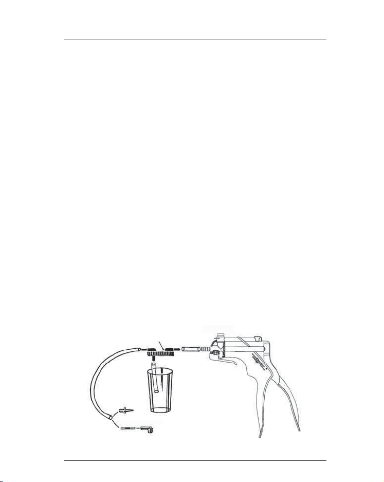
The kit provides a simple, clean, and quick method
for bleeding the fluid lines in the automotive brake
system. The creation of a vacuum in the reservoir
jar causes fluid to be drawn into the reservoir jar.
It should be noted that a tiny stream of bubbles
may be noticed in the hose after all of the air is bled
from the lines. This is caused by air seeping around
the threads of the loosened bleeder fitting and
being drawn back through the fitting by the suction
of the pump. Once the air is removed from within
the system, these tiny bubbles will in no way
jeopardize the bleeding operation, since they are
present only at the fitting and do not enter the
system. If you wish, you can put grease or Teflon
tape around the threads of the fitting to eliminate
most of the bubbles. The correct bleeding procedure
follows:
1) Always make certain that the master cylinder
reservoir is filled and that a supply of new, clean
brake fluid of the proper type is on hand to top off
the reservoir as the fluid level drops during bleeding.
Make sure that all the bleeding fittings are clean prior
to beginning of the bleeding procedure.
2) Bleed the hydraulic system in the following order:
A) Master cylinder bleeder fittings, if equipped.
If installing a new or rebuilt master cylinder,
follow the bench bleeding procedure which follows.
B) Bleeder fittings on the combination valve,
if equipped.
BRAKE BLEEDING
Page Number - 6 Form 824381

C) Wheel cylinders and calipers in succession
beginning with the wheel closest to the master
cylinder, and working to the farthest one.
NOTE: Follow manufacturer’s recommended bleeding
sequence (if known). The procedure given in this
article specifies to begin bleeding the wheel closest
to master cylinder. Regardless of sequence used,
always ensure all air is purged from system.
3) Slip 11⁄2” of tubing between the pump and the lid
of reservoir jar at port marked “TO PUMP”
(FIGURE 1).
4) Attach 31⁄2” plastic hose to the bottom of the cap.
5) Affix at least a 12” piece of tubing to the other
reservoir jar port. Be certain that the cover of the
reservoir jar is secure, but don’t over tighten.
6) Select the appropriate adapter(s). The L-shaped
universal adapters should fit snugly over the brake
bleeding fitting in order to seal properly. The
tapered adapters fit inside the thru-hole of fitting
and will generally seal well when inserted tightly
with a pressing and twisting motion. Attach adapter
to reservoir hose.
7) Place wrench on brake bleeding fitting.
Attach adapter and pump assembly, and pump
10 to 15 times.
NOTE: If bubbles coming out of the fitting are very
small and even in size, the air is probably coming
from within the system. It is not necessary to
eliminate these bubbles as they do not affect brake
operation. If desired, these bubbles can generally be
eliminated by placing grease or Teflon tape around
the threads, to act as a seal.
8) Open fitting slightly, only enough to cause the
fluid to enter jar, usually 1⁄4to 1⁄2turn.
9) After evacuating about 2” of fluid into the jar,
close the fitting and refill the master cylinder.
Repeat all previous steps on all remaining wheels.
If fluid is not drawn into the jar after opening the
fitting, make certain the lid of the jar is tight. You
will not be able to produce the necessary vacuum
in the jar if the lid does not fit securely. Occasionally
some dirt will get into the brake line, in which case
the pump may not be totally effective. If this
happens, have someone touch the brake pedal
once lightly, with the bleeding valve open, then
proceed to use the pump.
BRAKE BLEEDING
To Pump
FIGURE 1: BRAKE BLEEDING KIT
Form 824381 Page Number - 7

Page Number - 8 Form 824381
MOTORCYCLE BLEEDING PROCEDURE
Before bleeding the system, ensure that:
1) The brake caliper pistons are free to move
within the calipers.
2) The master cylinder piston is free to return to
the end of its stroke, and
3) Inspect the line to ensure that all fittings are tight.
FRONT BRAKE
1) Pump brake lever to seat caliper pads
against rotor.
2) Cover gas tank with plastic protective sheet
if using DOT 3 fluid (not necessary if using
DOT 5 fluid).
3) Remove master cylinder reservoir cap and
fill reservoir.
4) Select the appropriate adapter(s). The L-shaped
universal adapters should fit snugly over the brake
bleeding fitting in order to seal properly. The
tapered adapters fit inside the thru-hole of fitting
and will generally seal well when inserted tightly
with a pressing and twisting motion. Attach adapter
to reservoir hose.
5) Pump several times to create vacuum. Crack
bleeder valve with box wrench, extracting fluid into
reservoir. (Stop and add fluid when master cylinder
begins to get low. Do not allow air to enter line.).
At this point, all air should be out of system and
line full of fluid. (Note: if air is entering the pump
hose from around bleeder fitting, remove bleeder
fitting and apply Teflon tape to threaded portion
of bleeder screw only. This will prevent air seepage
around threads of bleeder screw.)
6) While maintaining vacuum on the pump line,
tighten bleeder fitting.
7) Top off reservoir and reinstall cover. Check brake
by pumping lever several times. Pedal should have
a positive, solid feel. If not, repeat bleeding process
as more air may have entered the system. Inspect
line to ensure all fittings are tight. If brake still feels
slack, consult a service technician.
For dual disc front brakes, repeat bleeding process
as though there are two separate systems.
REAR BRAKE
Removing all air from the rear brake line is the
same as for the front. The rear brake reservoir is
usually located beneath one of the side covers.
1) Remove the master cylinder cap and fill
to near full.
2) Attach the pump hose to the bleeder fitting and
pump the handle several times to create a vacuum.
3) Crack the bleeder with a box wrench. Because of
the short line, most of the air should be evacuated
the first time.
4) By closing the valve and repeating the process,
all of the air should be eliminated from the system.
Stop and add more fluid when master cylinder
gets low.
5) Top off and recap the reservoir.
TROUBLESHOOTING
1) If, after bleeding procedure, the brake continues
to be unresponsive, you may have water in the
system, in which case it will need to be disassembled
and cleaned by a qualified service technician.
2) If the brake squeaks slightly after bleeding,
the disc and pads must be cleaned.
3) Although DOT 3 fluid is recommended by
most manufacturers, it has a tendency to collect
moisture, which causes the common discoloration
you see - and that means decreased efficiency.
DOT 5 is silicone based and does not have the same
tendency to collect moisture. It also has a higher
tolerance. DOT 5, however, is not always easy to
find and the two types of fluid must not be mixed.
4) Rubber hoses are supplied stock on most
motorcycles, but they have a tendency to expand,
which may result in a spongy brake feel after a lot
of riding. Braided steel line will not expand like this.
BRAKE BLEEDING

Form 824381 Page Number - 9
BENCH BLEEDNG THE MASTER CYLINDER
Whenever a master cylinder has been removed
from a vehicle or a new one is being installed,
the master cylinder must be bench bled. Failure
to bench bleed is the main reason for unsuccess-
ful master cylinder replacement. Bench bleeding
greatly decreases the chance that any air will
be caught in the cylinder upon reinstallation.
Follow this procedure:
1) Plug outlet holes of the master cylinder and
gently clamp it in a vise with the push rod end
slightly elevated. NOTE: Damage may result if
master cylinder is clamped by the bore or if
reservoirs are clamped too tightly.
2) Fill the master cylinder with an approved type
brake fluid and keep it filled at all times during
the procedures.
3) Remove a plug from the master cylinder and
attach the proper adapter to this master cylinder
outlet port. Connect the pump tube to the reservoir
jar and the jar tube to the adapter (FIGURE 2).
4) Operate the pump and observe air and fluid
flowing into the reservoir until clear, bubble-free
fluid appears.
5) Plug the outlet tightly and repeat step 4 on the
other outlet ports.
6) Clamp master cylinder in a vise with the push rod
end down slightly. Slowly slide the master cylinder
push rod back and forth about 1⁄8”, until no air
bubbles can be seen in the reservoirs.
7) Remount the master cylinder with the push rod
end up and follow steps 3 & 4 on all outlet ports.
Plug ports tightly. The master cylinder is now free
of air and ready to install.
BRAKE BLEEDING
FIGURE 2: BENCH BLEEDING

MANUAL DEL USUARIO
¿Tiene alguna duda técnica?
Si tiene alguna duda, o requiere algún
servicio técnico, póngase en contacto
con nuestros técnicos de servicio
capacitados llamando al:
1-314-679-4200 ext. 4782
Lunes a viernes, de 7:30 a.m. a 4:15 p.m.
CST
Visite nuestro sitio web, www.mityvac.
com para ver nuevos productos,
catálogos e instrucciones de empleo
de nuestros productos.
¿Necesita piezas de servicio?
Para pedir piezas de repuesto o servicio,
visítenos en línea en www.mityvacparts.
com o llámenos al teléfono gratuito
1-800-992-9898.
Para obtener una versión en francés
o español de este manual visite
www.MityvacFST.com.
JUEGO DE PURGA DE
FRENOS AUTOMOTRIZ
MODELO MV8020
FEBRERO 2009 Formulario 824381 Section - MV75-1B

Formulario 824381 Número de página - 11
Piezas de Servicio y Accesorios........................................................12
Accesorios opcionales...............................................................13
Bomba de vacío...................................................................14
Purga de sistemas de freno ..........................................................15
Garantía ........................................................................28
CONTENIDO

PIEZAS DE SERVICIO Y ACCESORIOS
822391 – Tubo (2 piezas)
MVA6913 – Juego de
adaptador de purga MVA6912 – Juego de adaptador de
diagnóstico MVA6910 – Conectores
de tubos
JUEGOS DE SERVICIO DE LA BOMBA
Número de página - 12 Formulario 824381
10
5
3
1
14
12
11
16
815
13
3
9
7
6
4
2
824551 MVM8901 824550 824552 824553 824493
1 X
2 X
3 X
4 X
5 X
6 X
7 X
8 X
9 X
10 X X
11 X
12 X
13 X
14 X
15 X
16 X

Formulario 824381 Número de página - 13
ACCESORIOS OPCIONALES
Los siguientes accesorios opcionales están diseñados para mejorar y
ampliar la funcionalidad y las aplicaciones de las bombas de vacío de
mano de Mityvac.
MVA6825 JUEGO DE RELLENO DEL CILINDRO MAESTRO
Rellena automáticamente el cilindro maestro de frenos y embrague
con un nuevo fluido durante el procedimiento de purga de vacío. Se
adapta a botellas de fluido para frenos estándar de 12 y 32 onzas.
MVA6832 JUEGO DE RELLENO AUTOMÁTICO DE
SUJECIÓN CON TORNILLO DE PRESIÓN
Rellena automáticamente el cilindro maestro del freno y el
embrague con un nuevo fluido durante el procedimiento de purga
de vacío. Incluye un depósito de 40 onzas, o se adapta a botellas de
fluido estándar para frenos de 12 y 32 onzas. Ofrece características
y funcionalidad mejoradas con respecto a MVA6825.
MVA6834 JUEGO DE ACTUALIZACIÓN DE RELLENO
AUTOMÁTICO DE ESTILO PLACAS
Actualiza MVA6832 para incluir aplicaciones de relleno con holgura
limitada del cilindro maestro o cuellos de depósito que no son
estándar. Requiere la compra de MVA6832.
MVA6000 JUEGO DE ACCESORIOS AUTOMOTRICES
COMPLETOS
Contiene accesorios para probar y diagnosticar docenas de funciones
mecánicas de rendimiento del motor y automotrices, y para la purga
de embragues hidráulicos y frenos por parte de una persona.
MVA6005 JUEGO DE DEPÓSITO DE FLUIDO DE 16 ONZAS
Juego de depósito de fluido grande de 16 onzas para la purga de
frenos y recogida y distribución de fluidos.
MVA6845 JUEGO DE FRASCOS
Juego de accesorios para utilizar frascos estándar y de boca ancha
para la evacuación de fluidos o fluidos distribuidos a presión.
MVA6001 JUEGO DE TRANSFERENCIA DE FLUIDO
Contiene accesorios para sifonar, transferir, extraer o distribuir
fluidos usando una bomba de vacío de mano o una bomba de
presión Mityvac.
MVA6007 JUEGO DE PURGA DE ADAPTADOR DOBLE
Para la purga simultánea de sistemas de frenos de horquilla dobles
para motocicletas.
MANÓMETRO DE VACÍO MVA6178 CON ESCALA EN
PULGADAS DE HG
Manómetro de diafragma sin engranajes de 2” de diámetro con una
escala principal de 0 a 30 pulg de Hg y una escala de 0 a 100 kpa.
MANÓMETRO DE VACÍO MVA6179 CON ESCALA EN
MBARES
Manómetro de diafragma sin engranajes de 2 1/2” de diámetro con
una escala principal de 0 a 1000 milibares y una escala de 0 a 30
pulgada de mercurio.
MVA6180 MANÓMETRO DE VACÍO CON ESCALA DE KPA
Manómetro de diafragma sin engranajes de 2” de diámetro con una
escala de medida de 0 a 100 kpa.
MVA6825 MVA6832
MVA6000
MVA6834
MVA6005
MVA6845
MVA6001
MVA6007
MVA6179 MVA6180
MVA6178

Número de página - 14 Formulario 824381
La bomba de vacío es una herramienta de servicio
muy versátil que puede utilizarse para efectuar una
serie de tareas útiles. La bomba y sus accesorios
son útiles para transferir fluidos, purgar frenos y
ayudar en otras tareas.
DESCRIPCIÓN
La bomba de vacío portátil es sencilla, precisa, fácil
de usar y tiene muchas aplicaciones. Consta de un
cuerpo de bomba, palanca móvil y conexión. La
bomba se puede mantener fácilmente en la mano, y
cuando se aprieta la palanca, se produce vacío en la
conexión delantera.
ALIVIO DE VACÍO/PRESIÓN
El vacío pueden aliviarse levantando la palanca de
alivio. Esta acción permite la entrada de aire en el
sistema, aliviando así el vacío. El vacío también se
aliviarán cuando se desconecte la manguera de la
conexión delantera.
ESPECIFICACIONES
Vacío máximo a Apróx. 25” Hg
nivel del mar: (85 kPa)
Volumen de la embolada: 1 pulg3(16cc)
CUIDADOS ADECUADOS
La bomba es un instrumento de precisión de
construcción sólida. ¡Manéjela con cuidado! Cuide
la bomba y le proporcionará años de servicio sin
problemas.
LUBRICACIÓN
El lubricante de fábrica es un aceite de silicona que
permite usar la bomba durante mucho tiempo.
Si cree necesario lubricar la bomba, utilice un aceite
de silicona. Si no dispone de este aceite, utilice un
líquido de frenos a base de silicona DOT 5 (no DOT
3) o un aceite vegetal comestible. No utilice líquidos
derivados del petróleo ni lubricantes de rociado
(WD4O, aceite de motor, etc.) ya que se dañará
la bomba.
BOMBA DE VACÍO

Formulario 824381 Número de página - 15
Muchos sistemas de freno actuales vienen equipados
con funciones antibloqueo (ABS) y controles
electrónicos. Muchos de estos sistemas utilizan una
bomba eléctrica de alta presión para mantener el
sistema a presión. La reparación o purga de estos
sistemas de frenos requiere seguir procedimientos
especiales y tener en cuenta ciertas precauciones.
Observe las siguientes precauciones siempre que se
disponga a reparar sistemas de freno antibloqueo:
Lleve puestas SIEMPRE gafas protectoras cuando se
disponga a reparar sistemas de frenos de alta presión.
Descomprima SIEMPRE el sistema de freno antiblo-
queo antes de añadir líquido de frenos o antes de
reparar o realizar tareas de mantenimiento.
A menos que lo indique el procedimiento establecido
por el fabricante, no abra NUNCA ninguna válvula
de purga ni afloje ninguna tubería hidráulica con
el sistema de freno antibloqueo a presión. Utilice
SOLAMENTE líquidos de freno recomendados.
En vehículos equipados con sistemas de freno
antibloqueo, NO utilice líquidos de frenos a base
de silicona.
Para obtener información detallada sobre sistemas
de freno antibloqueo consulte siempre el manual de
reparaciones correspondiente.
ALIVIO DE PRESIÓN DE SISTEMAS DE
FRENO ANTIBLOQUEO
Para obtener información detallada sobre el
procedimiento de alivio de presión, consulte siempre
el manual de usuario del vehículo o un manual de
reparación apropiado. El procedimiento que se
indica a continuación suele ser válido para la
mayoría de los sistemas de freno antibloqueo.
Asegúrese de que el interruptor de arranque esté
en la posición de apagado, o desconecte el cable
negativo de la batería. Pise el pedal del freno de 25
a 40 veces. Cuando note un cambio considerable,
pise el pedal unas cuantas veces más. Esto aliviará
la presión en la mayoría de los sistemas. Abra con
cuidado el depósito del líquido de frenos o los tubos
del líquido de frenos. Rellene completamente el
depósito del líquido de frenos y cuando haya
terminado vuelva a conectar el cable de la batería.
PURGA DE SISTEMAS DE FRENO
ANTIBLOQUEO
Para obtener información detallada sobre el
procedimientos de purga del líquido de frenos,
consulte siempre un manual de reparación. Los
frenos delanteros en la mayoría de los sistemas de
freno antibloqueo se purgan manera convencional.
La mayoría de las bombas hidráulicas y acumula-
dores de presión están provistos de una válvula
de purga que se debe abrir para purgar el sistema
de frenos cuando el sistema haya perdido líquido
o se vaya a reemplazar. En algunos vehículos es
necesario que el sistema esté a presión al purgar
los frenos traseros. Algunos fabricantes automotri-
ces usan procedimientos de purga que requieren
equipos especializados.
PURGA DE LOS TUBOS DE LIQUIDO
DE FRENOS
La mayoría de los problemas relacionados con
pedales que haya que pisar demasiado o que se
sientan blandos suelen deberse a la presencia de
aire en los tubos hidráulicos, lo que hace necesario
purgar el sistema hidráulico. Este sistema puede
purgarse fácilmente usando la bomba y accesorios
de purga. Purgue las ruedas de una en una
empezando por la rueda más cercana al cilindro
maestro. El juego proporciona un método sencillo,
limpio y rápido para purgar los tubos del líquido de
frenos de automóviles. La creación de vacío en el
vaso del recipiente hace que el líquido sea aspirado
hacia el vaso. Se debe tener en cuenta que posible-
mente se observe un flujo pequeño de burbujas en
la manguera una vez que se haya purgado todo el
líquido de los tubos. Esto se debe a la aspiración de
la bomba que hace que se infiltre aire por las roscas
de la conexión de purga aflojada. Una vez que se
elimine todo el aire del sistema, estas pequeñas
burbujas no afectarán negativamente la purga,
ya que sólo están presentes en la conexión y no
pasarán al sistema. Si lo desea puede poner un poco
de grasa en las roscas de la conexión para eliminar
la mayoría de las burbujas. A continuación se indica
el procedimiento de purga correcto:
1) Asegúrese siempre de que el depósito del cilindro
maestro esté lleno y de tener a mano líquido
PURGA DE SISTEMAS DE FRENO

Número de página - 16 Formulario 824381
adicional de frenos nuevo para llenar al máximo
el depósito cuando el nivel de líquido baje durante
la purga. Asegúrese de que todas las conexiones de
purga estén limpias antes de empezar la purga.
2) Purgue el sistema hidráulico siguiendo este
orden: a) Conexiones de purga del cilindro maestro,
de haberlas. (Si va a instalar un cilindro maestro
nuevo o reconstruida siga el procedimiento indicado
a continuación para purgar en el banco de trabajo.
b) Las conexiones de purga de la válvula de
combinación, de haberlas. c) Los cilindros y
horquillas de las ruedas, en secuencia,
empezando por la rueda más próxima al cilindro
maestro y terminando por la rueda más alejada.
NOTA: Se recomienda seguir el orden del fabricante
(si se sabe). El procedimiento dado en este articulo
especifica que se debe empezar a purgar la rueda
más próxima al cilindro maestro. Sea cual sea el
orden usado, asegúrese de purgar todo el aire
del sistema.
3) Introduzca deslizando 1½” de tubo entre la
bomba y la tapa del vaso del depósito, en el orificio
marcado “TO PUMP” (a la bomba) (FIGURA 1).
4) Conecte un tubo de plástico de unas 12” a la
parte inferior de la tapa.
5) Conecte aproximadamente un tubo de 12” al
otro orificio del vaso del depósito. Asegúrese de que
la tapa del depósito esté bien cerrada, pero no la
apriete demasiado.
6) Seleccione los adaptadores apropiados. Los
adaptadores universales en forma de L deben
encajar de forma ajustada sobre la conexión de
purga del freno para sellarla debidamente. Los
adaptadores cónicos encajan por el agujero
pasante y generalmente producirán un buen
sellado cuando se introduzcan de forma apretada
con un movimiento de presión y torsión. Conecte el
adaptador a la manguera del depósito.
7) Ponga la llave en la conexión de purga del
freno, conecte el conjunto de adaptador y bomba y
bombee de 10 a 15 veces.
NOTA: Si las burbujas que salen de la conexión son
muy pequeñas y de tamaño uniforme, es probable
que el aire proceda del interior del sistema. No es
necesario eliminar estas burbujas ya que no afectan
el funcionamiento de los frenos. Si se desea,
generalmente se pueden eliminar estas burbujas
aplicando grasa o una cinta adhesiva de Teflon en
las roscas para actuar coma un sello.
8) Afloje un poco la conexión, sólo lo suficiente
como para hacer que el líquido entre en el vaso
(aproximadamente de 1⁄4a 1⁄2vuelta).
9) Apriete la conexión una vez evacuadas unas 2” de
líquido en el vaso. Mantenga el cilindro maestro lleno.
PURGA DE SISTEMAS DE FRENO
A la Bomba
FIGURA 1: JUEGO DE PURGA DEL FRENO

Formulario 824381 Número de página - 17
PURGA DE SISTEMAS DE FRENO
Repita todos los pasos anteriores en las demás rue-
das. Si no pasa líquido al vaso después de abrir la
conexión, asegúrese de que la tapa del vaso
esté bien apretada. Si la tapa no está apretada
firmemente no podrá generar suficiente vacío en el
vaso. Ocasionalmente entrará suciedad en los tubos
del líquido de frenos. En ese caso es posible que la
bomba no sea completamente efectiva. Si ocurre
esto, pida a alguien que pise el pedal del freno
ligeramente una vez, con la válvula de purga abi-
erta, y después continúe usando la bomba.
PROCEDIMIENTO DE PURGA EN
MOTOCICLETAS
Antes de purgar el sistema, cerciórese de lo siguiente:
1) Los pistones de la horquilla del freno se pueden
mover libremente dentro de las horquillas.
2) El pistón del cilindro maestro puede regresar
libremente al final de su carrera.
3) Inspeccione todas las conexiones del tubo para
comprobar que estén bien apretadas.
FRENO DELANTERO
1. Bombee la palanca del freno para asentar las
pastillas de la horquilla contra el rotor.
2. Cubra el depósito de gasolina con plástico si está
usando líquido DOT 3 (no es necesario hacer esto si
está usando líquido DOT 5.
3. Quite la tapa del depósito del cilindro maestro
y llénelo.
4. Seleccione los adaptadores apropiados. Los
adaptadores de presión (en forma de “L”) son de
distintos tamaños (pequeño, mediano y grande).
Debe poder apretarse bien en la conexión de purga
del freno para sellarlo bien. Los adaptadores
cónicos se ajustan dentro del agujero pasante de
la conexión y por lo general producirán un buen
sellado cuando se introducen de forma ajustada
haciendo fuerza y girando firmemente. Conecte el
adaptador a la manguera del depósito.
5. Bombee varias veces para producir un vacío.
Abra ligeramente la válvula de purga con una llave
de tubo para extraer líquido al recipiente. (Pare y
añada líquido cuando el nivel del cilindro maestro
sea bajo. No permita la entrada de aire en el tubo).
En este momento, todo el aire debe estar fuera del
sistema y el tubo debe estar lleno de líquido. (Nota:
Si entra aire en la manguera de la bomba alrededor
de la conexión de purga, quite la conexión de purga
y ponga cinta de Teflon solamente en la parte
roscada del tornillo de purga).
6. Apriete la conexión de purga a la vez que man-
tiene el vacío en el tubo de la bomba.
7. Rellene el depósito y vuelva a poner la tapa.
Compruebe el freno bombeando la palanca varias
veces. Al pisar el pedal se debe sentir una
resistencia firme y uniforme. Si no es así, repita
el procedimiento de purga, ya que puede haber
entrado más aire en el sistema. Inspeccione el tubo
para asegurarse de que todas las conexiones estén
bien apretadas. Si el freno parece estar aún flojo,
consulte con un técnico de servicio.
En el caso de frenos delanteros de discos dobles,
repita el procedimiento de purga como si se tratara
de dos sistemas separados.
FRENO TRASERO
El procedimiento para eliminar todo el aire del tubo
del freno trasero es idéntico al procedimiento para
el freno delantero. El depósito del freno trasero se
está ubicado generalmente debajo de una de las
tapas laterales.
1. Quite la tapa del cilindro maestro y llene el
depósito has casi Ilenarlo.
2. Conecte la manguera de la bomba a la conexión
de purga y bombee la palanca varias veces para
crear un vacío.
3. Abra ligeramente el purgador con una llave de
tubo. Debido a la cortedad del tubo, la mayor parte
del aire debe evacuarse la primera vez.
4. Al cerrar la válvula y repetir el proceso, se debe
eliminar todo el aire del sistema. Pare y añada más
líquido si baja el nivel en el cilindro maestro.
5. Rellene el depósito y vuelva a poner la tapa.

Número de página - 18 Formulario 824381
LOCALIZACIÓN Y RESOLUCIÓN
DE PROBLEMAS
1. Si, después del procedimiento de purga, el freno
sigue sin responder es posible que haya agua en el
sistema, en cuyo caso tendrá que ser desmontado y
limpiado por un técnico de servicio capacitado.
2. Si el freno chirría ligeramente después de purgarse,
habrá que limpiar el disco y las pastillas del freno.
3. Aunque la mayoría de los fabricantes
recomiendan el líquido liquido DOT 3, este tiene
tendencia a acumular humedad causando la pérdida
de color común que se puede observar, lo que
significa una menor eficiencia. El DOT 5 está
basado en silicona y no tiene la misma tendencia
a acumular humedad. Por otro lado, el DOT 5
no es fácil de conseguir, y los dos líquidos no
deben mezclarse.
4. Las mangueras de goma son materiales de uso
general en las motocicletas, pero tienen la tendencia
de expandirse, lo que puede resultar en una
reacción esponjosa del freno después de haber
conducido el automóvil durante mucho tiempo. Las
mangueras de acero trenzado no se expandirán así.
PURGA DEL CILINDRO MAESTRO EN EL
BANCO DE TRABAJO
Siempre que se quite el cilindro maestro de un
vehículo o que se instale uno nuevo, se debe purgar
el cilindro en el banco de trabajo. No purgar este
cilindro en el banco es la causa principal de hacer
sustituciones incorrectas del cilindro. La purga en
el banco de trabajo reduce considerablemente la
posibilidad de que entre aire en el cilindro después
de volverlo a instalar. Siga este procedimiento:
1) Tapone los orificios de salida del cilindro maestro
y sujete el cilindro en una prensa de banco sin
apretar mucho y con el extremo de la varilla de
empuje un poco sacado. NOTA: Se puede dañar el
cilindro si se sujeta por el interior o si los depósitos
están demasiado apretados.
2) Llene el cilindro maestro con un líquido de
frenos adecuado y manténgalo lleno durante
todo este procedimiento.
3) Quite un tapón del cilindro maestro y conecte el
adaptador apropiado a este orificio de salida del
cilindro maestro. Conecte el tubo de la bomba al
vaso del depósito y el tubo del vaso a la manguera
al adaptador (FIGURA 2).
4) Accione la bomba y observe el paso de aire y
líquido al depósito hasta que aparezca un líquido
transparente sin burbujas.
5) Tapone bien el orificio de salida y repita el paso
4 en los otros orificios de salida.
6) Sujete el cilindro maestro en un tornillo de banco
con el extremo de la varilla de empuje ligeramente
bajado. Deslice lentamente la varilla de empuje
del cilindro maestro hacia adentro y hacia afuera
aproximadamente 1⁄8”, hasta que no observe
burbujas de aire en los depósitos.
7) Vuelva a montar el cilindro maestro con el
extremo de la varilla de empuje hacia arriba y re-
pita los pasos 3 y 4 con los demás orificios de
salida. Tapone bien los orificios. Ahora, el cilindro
maestro estará purgado y listo para instalarse.
FIGURA 2:
PURGA EN BANCO DE TRABAJO
PURGA DE SISTEMAS DE FRENO

MANUEL D’UTILISATION
Une question technique?
Pour toute question ou en cas de besoin
d’assistance technique, prendre contact
avec nos techniciens spécialisés au :
1-314-679-4200, poste 4782, lundi – ven-
dredi, 7 heures 30 à 16 heures 15 (heure
normale du Centre des Etats-Unis)
Visiter notre site Web à www.mityvac.
com pour nos nouveaux produits, nos
catalogues et le mode d’emploi de nos
produits.
Besoin de pièces détachées ?
Pour commander des pièces détachées,
nous rendre visite en ligne à www.mity-
vacparts.com ou nous appeler sans frais
au 1-800-002-9898.
KIT DE PURGE DE
FREIN AUTOMOBILE,
MODÈLE MV8020
FÉVRIER 2009 Document 824381 Section - MV75-1B

Page numéro - 20 Document 824381
TABLE DES MATIÈRES
Pièces détachées et accessoires........................................................21
Accessoires optionnels ..............................................................22
La pompe .......................................................................23
Purge des freins ..................................................................24
Garantie ........................................................................28
Table of contents
Languages:
Other Mityvac Tools manuals
Popular Tools manuals by other brands

Martor
Martor SECUNORM 500 quick start guide

Triton
Triton Maxi ETA300 Operating and safety instructions

Silver Eagle
Silver Eagle SE1214 quick start guide

Atlas Copco
Atlas Copco SMC-50-2100-POSI-L Product instructions

Powerfix Profi
Powerfix Profi 96475 Operation and safety notes

UTILCO
UTILCO UR-4PT instruction manual