Cherry Aerospace G84-LS User manual

ORIGINAL INSTRUCTIONS
G84-LS
Split Riveter
1224 E. Warner Ave
Santa Ana,CA92705
www.cherryaerospace.com

THE CHERRY®G84-LS SPLIT
RIVETER TABLE OF CONTENTS
Technical Specifications..............................................................................................................................................2
Recommended Usage................................................................................................................................................. 3
Reconfiguring for Pistol Grip or In-Line operation.................................................................................................3
Operational SafetyWarnings..............................................................................................................................3
Maintenance and Repair..............................................................................................................................................4
Recommended Fluid ......................................................................................................................................... 4
Dexron III Oil Safety Data .................................................................................................................................. 4
Protecting the High Pressure Hoses ................................................................................................................... 5
Un-wrapping Hoses...........................................................................................................................................5
Fill and Bleed Instructions ..................................................................................................................................5
Replenishing the Hydraulic System with Fluid...................................................................................................... 5
Bleeding...........................................................................................................................................................6
Tool Overhaul ...................................................................................................................................................6
Assembly of Double Delta Air Valve Sub-Assembly.......................................................................................6
Head Sub-Assembly...................................................................................................................................7
Handle Sub-Assembly................................................................................................................................. 7
Tool Care..........................................................................................................................................................8
Troubleshooting ................................................................................................................................................ 8
Parts List...........................................................................................................................................................9
Exploded View................................................................................................................................................ 10
Cross Section Drawings................................................................................................................................... 11
Declaration of conformity..............................................................................................................................Back Cover
Warranty .....................................................................................................................................................Back Cover
DESCRIPTION
The G84-LS is a powerful, rugged, compact split riveter designed for ergonomic, high speed and reliable operation. Adaptors areavailable
for mountingmost Cherry pulling heads; it will install most popular sizes and types of aircraft pull type fasteners including lock-bolts, blind-bolts,
etc.
Thistool may beconfigured for comfortable left hand, right hand, in-line or pistol-gripoperation. Thetrigger handlemay alsobepositioned away from
the headassembly, for remoteactivation (similar to theG84-LSR). This allowsfor superior ergonomics and greater accessibility in obstructed
applications.
TECHNICAL SPECIFICATIONS
Specificationsshownhereinaresubject tochangealso
Contact us for thelatestinformationavailableon any
SPECIFICATIONS:
OPERATINGAIRPRESSURE90to110psi(6,2-7,6bar
AIR QUALITY Clean, Filtered
HOSE LENGTH 10 Ft. (3,05 m)
PISTONSTROKE 0.530 inch (13,5 mm)
PULLING FORCE 5,700 lbs. @ 110 psi
(25,35kN@6,9bar)
RETURN FORCE 2000 Lbs max.
(8,89 kN max)
WEIGHT
HAND HELD UNIT 3.0 lbs. (1,3 kg)
TOTAL 11.8 lbs. (5,3 kg)
NOISE LEVEL 66.5 dB (A)
VIBRATION 4.0 m/s2
AIR CONSUMPTION 0.34 SCF/cycle
2 (9,63 L/cycle)
RECOMMENDED USAGE
This Riveter is designed to install pull type fasteners in conjunction with
compatible pulling heads.
Pulling heads suitable for G84-LSR or comparable riveters will mount directly with no
adaptation. Most Cherry®pulling heads may be used with appropriate adaptation (see
table). Note: The unit may be used for other applications if it operates within the given
parameters, and appropriate safety precautions have been taken.
Contact Cherry®Technical Services for more information.
PULLING HEAD INSTALLATION:
Connect air source prior tomounting anypulling head; mount per
manufacturer instructions.
RIVETER OPERATION
Hold the handle firmly and depress the trigger.
Once the operation is completed, release trigger.
Thetool may be configured prior touse for In-Line or Pistol Grip (figures 1 and 2) as
necessary; see belowforinstructions. It may also beconfigured for remoteactivation
(similar to G84-LSR)
OPERATIONAL SAFETY WARNINGS
Tool must be operated, repaired and maintained only by
trainedpersonnel
Make sure pulling head and riveter are in good working
condition; operating a defective unit will lead to hazardous
conditions
Ensure that the air vent holes are not obstructed and that
the fittings, hydraulic hoses and wrapping are in good
workingcondition
Use approved eye protection at all times while operating or
performingmaintenanceonthistool
Use appropriate personal protection equipment for the
environmentthetool operates within.
Use stem deflector 530A16 with plug 744-503 when
installing break stem fasteners with straight pulling heads
(brokenstemsmay exit thisconfigurationat highvelocity)
Make sure that the selected pulling head is mounted
correctly and equipped with appropriate safety features. Do
not operate witha damaged stem deflector.
Use only within the given operating capability
Do not exceed the recommended air pressure.
Never point thetool or pulling headtowards any person
Before disassembling the tool read the maintenance and
repair instructions carefully
Always disconnect from the air source be- fore servicing,
adjusting.
Do not use substitutesfor components. Modificationsare at
customer’s entire risk and responsibility.
Avoid excessive contact with the fluid to avoid the
possibility of skin rashes; wear rubber gloves if
necessary. Wash thoroughly after contact with the
fluid.
Do not pound on the rear of the head cylinder (744-150) to
forcefastenersintoholesasthiswill damagethetool
Altering the riveter configuration in anyway out- side of the
current instructions is not acceptable.
Direct tool operation and safety questions and concerns to
Cherry®
RECONFIGURING TOOL GRIP FOR ACCESSIBILITY
Inline(figure 1), Pistol Grip (figure 2) as well as Left/Right Handed configuration are possible.
Thestandard factory configurationis Pistol Grip, Right Hand operation.
Thehandlemay also bemoved away from thehead assemblyfor remoteactivation(similar to theold
G84-LSR).
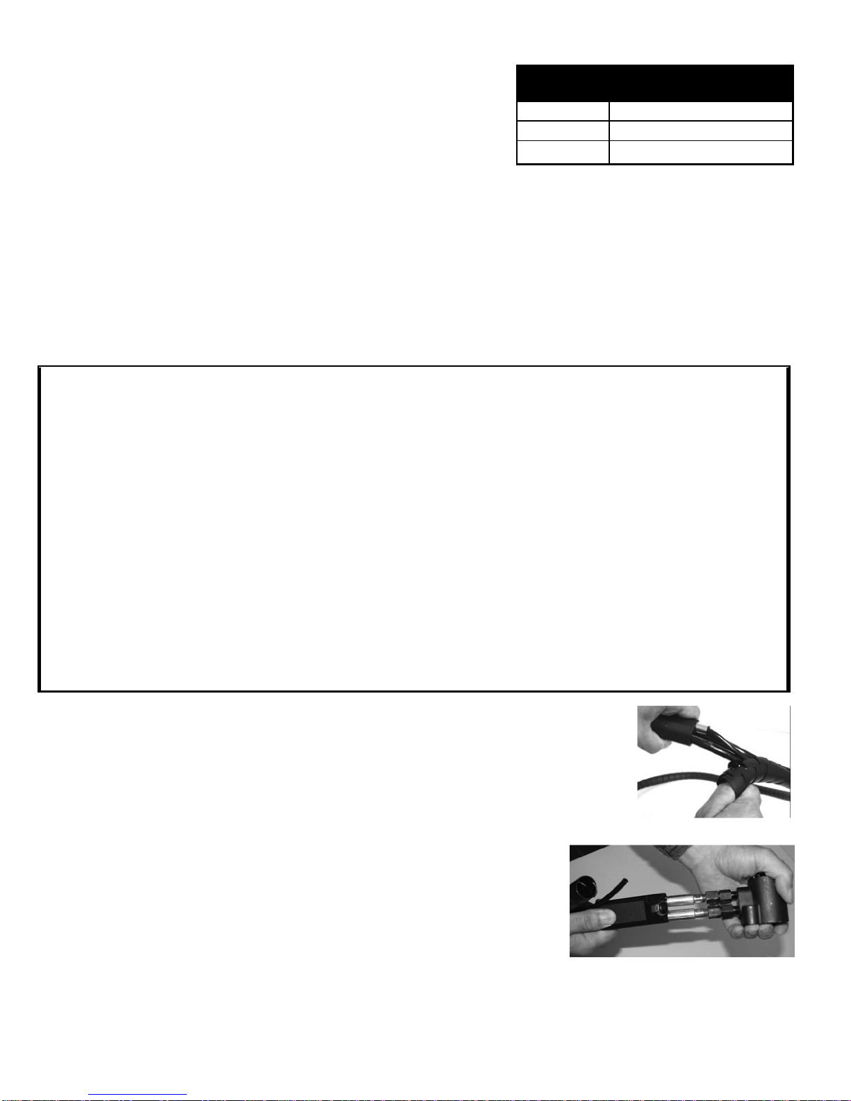
To reconfigurefor in-line operation (refer to Parts List and Exploded View on pages 9):
1. Removetheair sourceandplacehead cylinder higher then thepower unit, over apan to
containfluidspills.
2. Pull someof thehose wrapfrom under thehandlegrip( figure 3)
3. 3 Slidehand grip(80) away from thehead(figure4),identify“P” from “R” hoseand unthread
thefittings.
4. Removeplugs(69); threadandtightenthehosefittingsintheirplacemaking suretomatchthe
P and Rports withtheright hoses.
5. Threadthe plugs (69) intothevacated holes andtightenthem securely.
6. Fill andbleedperpage5.
CAUTION: Thisoperation to be performed bytrained personnel only!
3
Adapter To Adapt to Tool Mounting
System
744-500 Cherry® G744 mount
744-600 Cherry® G704B/747/746A
744-700 Cherry® G83/G84 Bayonet
Figure 3
Figure 4
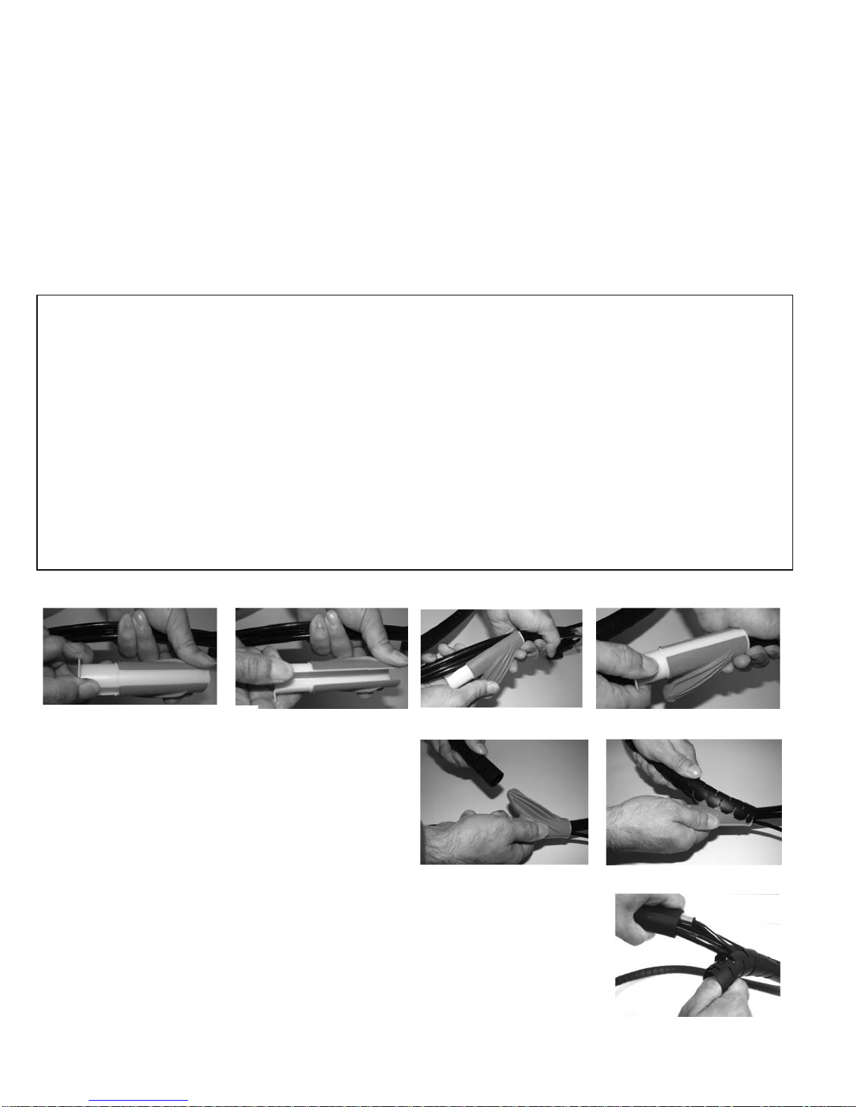
Figure5
Figure7
Figure8
Figure 10
Figure9
Figure11
Figure 6
TOOLSNEEDED:
P1444
PROCEDURE:
Follow step in figures 5 through 10; holdthe installed wrap with
onehand, while slidingthetool P1444 over theentire hoselength
(similar to usinga zipper) to complete the operation.
Wraptapearoundthe 2 ends ofthewrap.
UN-WRAPPING HYDRAULICHOSES
Figure 12: Unwrap thetapethen pullthe wrap sideways starting
from one end(figure 11).
MAINTENANCE AND REPAIR
Note: Minor fluid loss over time at the piston rod is normal, and does not indicate seal damage.
See troubleshooting guide (page 8) for simple tips on when tool maintenance or repair is necessary.
Always remove the air source from the tools prior to performing any maintenance work.
Establish a maintenance schedule according to your production needs to ensure optimum riveter operation
Inspect routinely for fluid leaks around plugs, screws and fittings, moving parts.
RECOMMENDED FLUID
Automatic transmission fluid, Dexron®III (no substitutes).
PROPERTIES: Specific gravity: 0.863
Weight per gallon: 7.18 lbs.
Open flash point: >200°C (392°F)
RECOMMENDEDBRAND: ATF Dexron®III. Thedata hereinisfor your reference; for thelatest MSDS, check withthefluidmanufacturer.
DEXRON III®FLUID SAFETY DATA
HANDLING: Eye protectionrequired. Protectivegloves,
chemical-resistant bootsand apron arerecom-
mended.
Use in well ventilated area.
FIRST AID
If irritation develops, please consult a physician.
Skin:Wash thoroughly with soapand water as soonas pos-
sible. Casual contact requires noimmediate attention.
Eyes: Flush with abundant water.
Ingestion: Seek medical attention immediately.
DO NOT INDUCE VOMITING.
Inhalation:Removefrom contaminated area; apply artificial
respirationif needed. If unconscious, consult physician.
No significant adverse healtheffects expectedfrom short
term exposure.
ENVIRONMENT
Storage: Avoid storage near anyignition source, including
open flame
Waste Disposal: Inaccordancewithapplicableregulations.
Spillage: Prevent entryintodrains, sewersand water
courses. Soak up with diatomaceous earth
or other inert material. Dispose in
accordance with applicable regulations.
Combustibility: Slightly combustible if heated above flash
point.It will releaseflammablevapors
which can igniteor be explosivein con-
fined spacesif exposedtosource of ignition.
Fire: Use suitable extinguishingmedia: dry powder, foam,
and CO2 or water fog. Do not use water jets.
PROTECTING THE HIGH PRESSURE HOSES
4
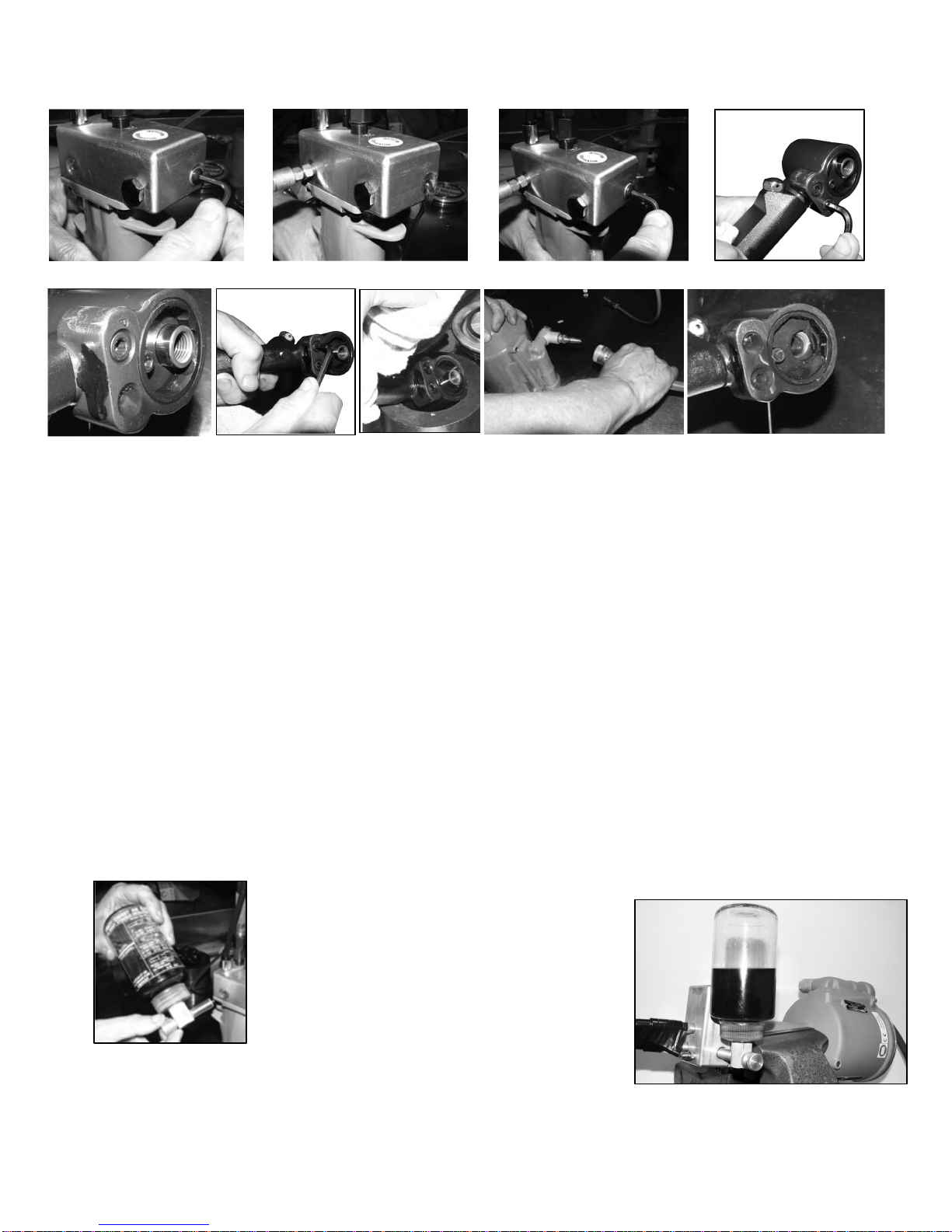
Figure 12
Figure 16
Figure 17
Figure 13
Figure 1
4
Figure 19
Figure 18
Figure 20
FILL AND BLEED
Required tools: Pressurized oil sourcewith correct fitting (#10-32)
A. Replenishing the fluid (refer to page 9 for Component List)
This operationis necessary when a major fluidlossoccurred.
Connecttoanairsource
Depress and hold the trigger; disconnectfrom the air source whileholdingthetrigger depressed.
Makesurethepistonisfullyretracted;ifnot,pressitmanually.
Figure 12: Removethescrews (33) from thesideand back of manifold(35)
Figure 13: Threada pressurized fluid sourceinto thesidehole; pump fluid untilit flows out smoothly, without any bubbles.
Figure14:Threadandtightenthecapscrew.
Figure15: Remove“R” plug (69) from theheadcylinder
Figure16: Pump fluid until it flows smoothly, without airbubbles
Figure17:Threadinandtighten“R”plug(69)andremove“P”plug(69).
Figure 18: Placea clothover thehead cylinder to containthe air and fluidthat will squirt out of the“R” port
Figure19:Connectriveterto an airsourceandthenremovecloth
Figure 20: Pump fluid until it flowssmoothly withno air bubbles
Thread-inandtightenthe“P”plug(69);bleed per instructions given below.
B. Bleeding Instructions (air removal and fluid refill for an already primed tool):
Requiredtools: Air Bleeder P/N700A77.
Procedure:
Removescrew(33)andattachtheairbleeder(700A77)
Connect riveter toanairsource
Place thehandlesubassembly (744-189) sideways ina
vise, withthe headcasting(744-202)placed belowit;
makesurethat the air bleeder in up-side down (see picture
on theright).
Push and release trigger several times, observing the
fluidinside the Bleeder bottle; repeat until noair bubbles
areobserved inthe bottleduringoperation
Disconnect theair bleeder and seal by tighteningscrew (33)
Caution: Do not depress the trigger before the screw(33) is tightened.
5
Figure 15

P1444
TOOL OVERHAUL
Tool overhaul is needed in case of tool malfunction, massive fluid loss or as part of your routine maintenance program.
TOOLS NEEDED: G84-LSKT – tool kit,
Needle Nose Pliers,
G84-LSKS – service kit: complete seal and fastener set for tool overhaul
OVERHAUL PROCEDURE
Caution:
Maintenance andrepairtobeconductedonlybytrainedpersonnel.
Priortoattemptinganyrepairormaintenancework,make suretheairisdisconnected.
Followtheseinstructions. Use special carehandlingsealing surfaces.
Apply anO-ringlubricant(Parker®siliconelubeor equivalent)onall O-ring s.
After tooloverhaul,fill with DEXRON III ATFfluid and bleed (see page 5).
AIRVALVESUB-ASSEMBLY
Disassembly Instructions:
Remove retaining ring (56) andmuffler (55).
Insert thevalve plug extractor P1178intotheend of valveplug (54) andpull it out.
Pullout thevalve spool subassembly(86) the sameway.
Note: In the unlikely event thevalve sleeve (47) isirreversibly clogged, removeit as follows:
Grab one end of spring(49) withneedle-nosepliers andturn/pull to dislodgeit from it’s groove
After springremoval, pull out the valvesleeve(47)by using theremoval tool 837B740.
Assembly Instructions: Reverse the above procedures.
Caution: Install valve sleeve (47) carefully with your fingers: gently push and wiggle it to allow
O-rings to slip in. Install spring (49); use tool 836B740 to push it firmly into the groove.
836B740
Valve Spring Installation Tool
P1178
Valve Plug Extractor
744-104
Seal Guide
744-195
530-202 700A77
Air Bleeder
G84
-
LSKT TOOL KIT
837B740
Valve Sleeve Removal Tool 700A61
Piston RodWrench
530-201
744-194
6

HEAD CYLINDER SUB-ASSEMBLY (744-202)
Caution: Remove Pulling Heads or other attachments before attempting to disassemble.
Disassembly instructions:
Remove screw (57) and unscrew lock ring (58) with spanner wrench 530-202.
Drainthefluidover an oilpan; dispose according to environmental regulations.
Remove rear stop (59) and piston (63) by pressing them out of the rear of the subassembly.
Remove seals(60, 61, 62, 63, 65, 66, 67 & 68)carefully using a benthook tool.
Assembly instructions:
Inspect allcomponentstomakesure all surfaces arecleanand freeof burrs.
Install O-ringand back-up ring (67& 68) intogroove of head cylinder (70).
Thread seal guides 744-194 & 744-195 onboth sidesof the piston (64).
Mount O-ring andback-up ring (65& 66) onto the piston (64).
Carefully push/twist piston (64) intothe headcylinder (70) bore, pressing it allthewayin.
AssembleO-ring, backup ring (60& 61) and O-ring, Back-up ring (62&63) ontorear stop (59) andcarefully
pressitintothe headcylinder.
Thread-inlockring (58)using spanner wrench 530-202and secureit with screw (57);
use Loctite® 242on threads. Remove seal guides.
Swivel Assembly Instructions:
Apply Loctite 545on themalethreads of swivel (75).
Thread swivel (75) into head cylinder(70) and thread untilhand tight.
Using a 7/16 wrench, tighten threads by rotatingone fullturn from initial threadseating
tosecurein place – Do notovertighten.
AllowLoctitetocurefor 24 hours for full strength.
HANDLE SUB-ASSEMBLY (744-189)
Disassembly Instructions: Make sure that the air supply is disconnected before proceeding.
Unscrewcap screws (19) and removemanifold(35);
Drainthefluidcompletelyintoa pan anddispose accordingtoenvironmental regulations.
Remove gasket (22) andO-rings(21)
Remove retaining ring (1)and the base cover (2) from the bottom of the unit.
Remove retaining ring (3)and carefully pryhandle base (4) from thebottom of the unit, using a screwdriver.
Engage wrench 700A61 intothehex socket of the piston rod cap(26).
Remove locknut (6) with a ½inch (13mm) socket, while holdingwith the wrench; unscrew air piston (7) by using
wrench530-201anda1inch(26mm)socket.
Pullthe air piston(7) out through thebottom of the unit withthe helpof thetool P1178.
Remove powerpiston subassembly (84) throughthe top of the handle (18) usingthe guide tool 744-104.
Remove thepacking plug (11) with the helpof wrench530-201 and a 1¼ inch (32 mm) Socket.
Note: Toloosenit, holdthe handleupsidedown in avise, if necessary.
Remove theO-rings (12 and 13)and back-up rings(14) with athin, bent hook.
Placean 1inch(25,4mm)rod on top of power cylinder (17) andtap it out carefully throughthe bottom of theunit
with amallet.
Assembly Instructions: LubricateO-ringswithParker®siliconeO-ringlube or equivalent and handle allseals with care.
Makesure thegasketsand sealsarein goodcondition andare placedcorrectly.
Insert the power cylinder (17) withO-rings(15 & 16) intothe handle(18) bore through the bottom of handle. To
properly seat it, place an 1inch(26 mm) bar against itsbottom surface, andcarefully tapinto place with amallet.
Insert O-rings(13) and back-uprings (14) inpacking plug (11).
Thread packing plugin tightlyagainst the power cylinder (17) using wrench 530-201 and a1 ¼ inch (32 mm)
socket.
Thread seal guidetool 744-104intothe end of thepower piston (25) thenpush intothe boreof the powercylin-
der (17) through thetopof handle(18).Tapitthoughthepacking plug (11) with amallet; remove the seal guide.
Using wrench530-201 insert air piston (7) with quad ring (9) and back-up rings(8) intothemain bore of the han-
dle (18) untilit engagesthe threadedend of the power piston (25); tightenthem together wrench 700A61.
Thread and tighten locknut (6) onto power piston (25) with a ½” socket (13 mm) at 50 to 59 in-lbs (5,65
to 6,67 N-m).
Insert handle base (4) withlubricatedO-ring (5) intothe bottom of thehandle (18) and tap it intoits seat.
Placeretainingring (3), basecover(2), andretaining ring (1).
Pushthe piston downwardswith the helpof wrench700A61.
Fill the handle subassembly withfluidtoabout 1/8inch(3mm)above thetop of thepowerpiston(17).
Place new gasket & O-rings(21,22) ontop of handle (18); mount the manifold(35) tightening screws (19) evenly.
7

TOOL CARE
This tool has been designed for optimum service with minimum care.
In order to extend the life of the tool, please follow the simple instructions given below:
Make sure the system is filled properly with fluid and is free of air (see fill and bleed instructions)
Do not use any substitutes for DEXRON III ATF or spare components
Use only clean air; dirt and moisture will cause damage to the pneumatic system.
Inspect for air and fluid leaks routinely. Minor fluid loss over time is normal, but increased fluid or air loss indicates seal damage. Make
sure that all fittings are properly tightened and secured.
Do not operate with hoses unprotected or with a damaged hose wrap.
Perform regular maintenance.
TROUBLESHOOTING GUIDE
PROBLEM POSSIBLE REASONS / SOLUTIONS
- No air supply is connected:
Connectto aclean, filtered air source at 90to110 psi (6,2to7,6 bar).
- Faultytrigger: Remove and replace trigger assembly.
Piston does not moveafter depressing Trigger
- Broken power piston: Servicethe HandleSubassembly per page 7.
Short stroke or low pull force -Significant fluid loss: Bleed the system per page5.
If performance doesn’t improve, or excessiveleakagecontinues, see below.
-Leaks around the plugs(69)orfittingsindicate thatthey are not tightened to seal
properly: Tighten until nomoreleaks areobserved.
-Leaks at the front or back of head cylinder (70) indicate worn or damaged
seals:
Head Cylinder Fluid leakage
Servicehead cylinder per page7.
-Broken or dislodged spring (49).
Air leakage at the valve -Worn or damaged valve spool seals: Disassemble and service airvalveper Air
Sub-AssemblyOverhaul Instructions.
- Piston orseal damage: Service head cylinder per page7.
-Oil bypassing dueto power piston (25) displacement Ofitsseat in subassembly
(84): ServiceHandle Subassemblyper page7.
-Clogged muffler (55) or air filter (51): Cleanthoroughly withsolvent and back-
blowwithcompressedair.
Head piston (64) is slow or seizes
-Lockring(item 58) is notsecured duetoloose cap screw(57): Tighten lock-ring,
andthen secureitbytightening capscrew.
UseLoctite®removablethreadlockertosecureit.
-Pressurerelief valve (85) malfunction: Removevalve then O-ring (42) from the
manifold(35). Cleanand drythoroughly components. ReplaceO-Ring (use Parker®
siliconeO-ringlube or equivalent). Re-assemblevalve; makesuretheO-ring (42) is
seated concentrically insideof thevalvecavity beforeinstalling theBall-seat(41)into
themanifold(35).
Head Piston (64) does not return fully forward
even aftersystem bleeding
-Compression spring (31) is damaged or broken: Removehandlemanifold(35)
andreplacethedamaged spring. Re-assemble, fill and bleed per page 5.
Cherry®is well known for the quality of our tools and our outstanding customer support.
If the tool does not perform at the expected performance please contact our representatives.
LOCTITE®is a registered trademark of Henkel Corporation
DEXRON®is a registered trademark of GM Corporation.
PARKER®is a trademark of Parker Hannifin Corporation
8

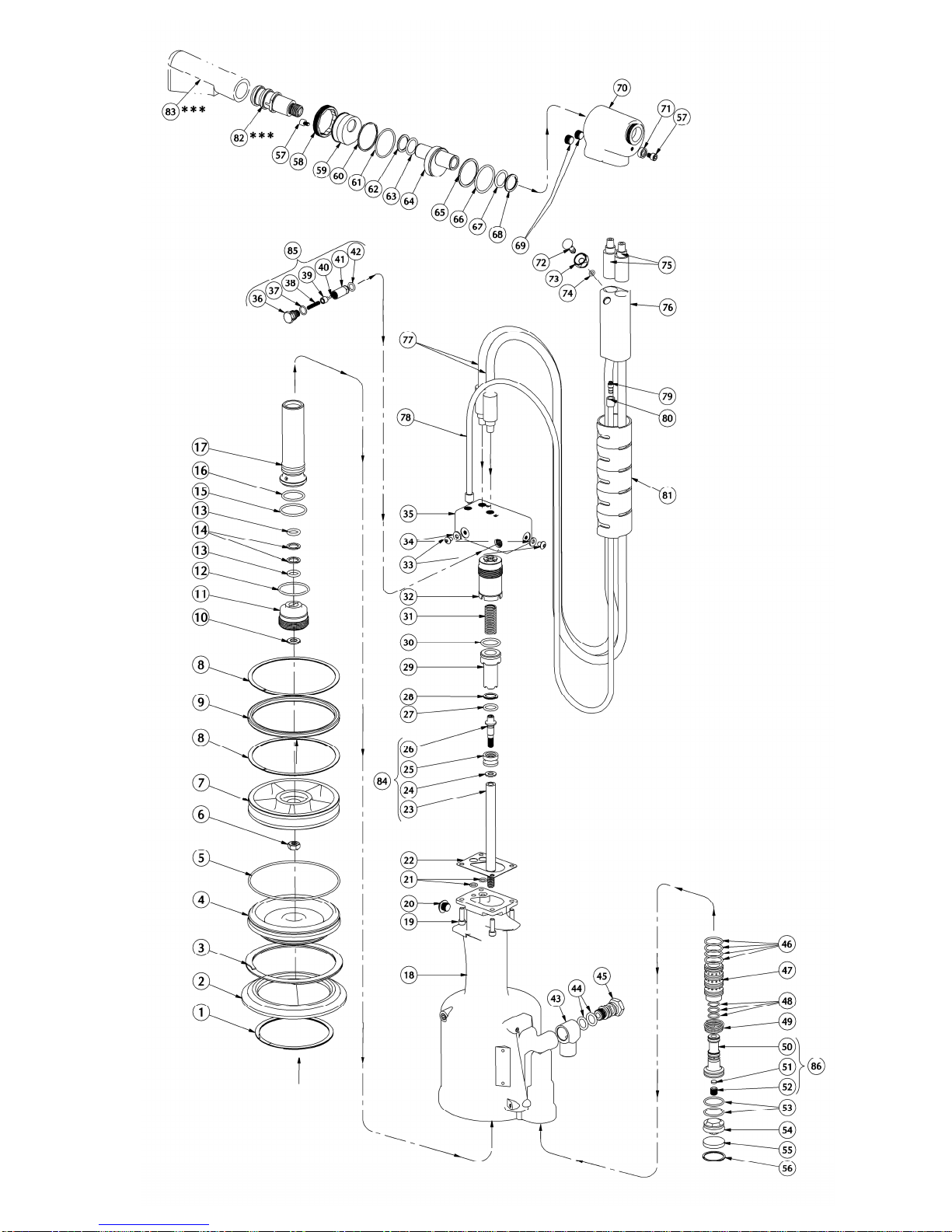
ITEM NO. PART NO DESCRIPTION QTY
744-189 Sub-Assembly, Handle 1
1 P884 Ring, Retaining 1
2 740B5 Cover, Base 1
3 P886 Ring, Retaining 1
4 740C4 Base, Handle 1
5 P890 O-Ring 1
6 P1392 Nut, Conelok 1
7 744-094 Piston, Air 1
8 P909 Ring, Back-Up 2
9 P887 Ring, Quad 1
10 744-095 Washer, Air Piston 1
11 744-165 Plug, Packing 1
12 P889 O-Ring 1
13 P1405** O-Ring 2
14 P1410 Ring, Back-Up 2
15 P892** O-Ring 1
16 P833** O-Ring 1
17 744-161 Cylinder, Power 1
18 743A11 Handle 1
19 P73 Cap Screw, Soc. Head 4
20 530A113 Cap Screw, Button Head. 1
21 P832** O-Ring 2
22 744-171 Gasket, Manifold 1
84 744-122 Sub-Assembly, Power Piston And
Rod 1
23 744-164* Rod, Power Piston 1
24 740A12* Stop, Piston 1
25 744-163* Piston, Power 1
26 744-087* Cap, Piston Rod 1
27 P1406 O-Ring 1
28 P213 Ring, Back-Up 1
29 744-160 Piston, Return 1
30 P104 O-Ring 1
31 P1414 Spring, Compression 1
32 744-175 Cylinder, Return 1
33 P573 Screw, Button Hd. Cap 2
34 P572 Stat-O-Seal 2
35 744-188 Manifold, Handle 1*
85 700-214 Sub-Assembly, Relief Valve 1
36 700-218 Seat, Spring 1
37 P383 O-Ring 1
38 P1366 Spring 1
39 700-217 Piston, Valve 1
40 P688 Ball 1
41 700-215 Seat, Ball 1
42 P111 O-Ring 1
43 530A34 Swivel 1
44 P195 O-Ring 2
45 530A35 Swivel Bolt 1
ITEM
NO. PART NO. DESCRIPTION QTY
46 P268 O-Ring 4
47 740B14 Sleeve, Valve 1
48 P891** O-Ring 3
49 740A18 Spring 1
86 740A15 Sub-Assembly, Valve Spool 1
50 740B15-1* Spool, Valve 1
51 700A18* Filter 1
52 700A69* Screw, Metering 1
53 P848 O-Ring 2
54 740B16 Plug, Valve 1
55 740A17 Muffler 1
56 P321 Ring, Retaining 1
744-202 Sub-Assembly, Head Cylinder 1
57 P85 Screw, Soc. Hd. Cap 2
58 744-144 Lock, Ring, Power 1
59 744-142 Stop, Rear 1
60 P1419 Ring, Back-Up 1
61 P1420 O-Ring 1
62 P1411 Ring, Back-up 1
63 P1407 O-Ring 1
64 744-140 Piston, Head 1
65 P1412 Ring, Back-up 1
66 P1409** O-Ring 1
67 P1408** O-Ring 1
68 P209** Ring, Back-up 1
69 P698 Pipe, Level Seal 2
70 744-168 Cylinder, Head 1
71 744-145 Stop, Pulling Head 1
703A33 Sub-Assembly, Trigger 1
72 530A38 Trigger 1
73 703A32 Sleeve, Trigger 1
74 P223 O-Ring 1
75 744-150 Swivel, High Pressure 2
76 744-185 Trigger, Manifold 1
77 P1415 Assembly, High Pressure Hose 2
78 744-186 Air Tubing 1
79 P1453 Barbed Air Fitting 2
80 P1452 Tubing Clamp 2
81 744-193 Cable Wrap 1
82 744-503*** Fitting, Pin Deflector (sold separately) 1
83 530A16*** Pin Deflector (sold separately) 1
9
PART LIST FOR THE G84
-
LS SPLIT RIVETER (744
-
190)
* Only within subassembly; component not sold separately.
** No Substitutions
*** Not provided in standard configuration - to be purchased as needed.
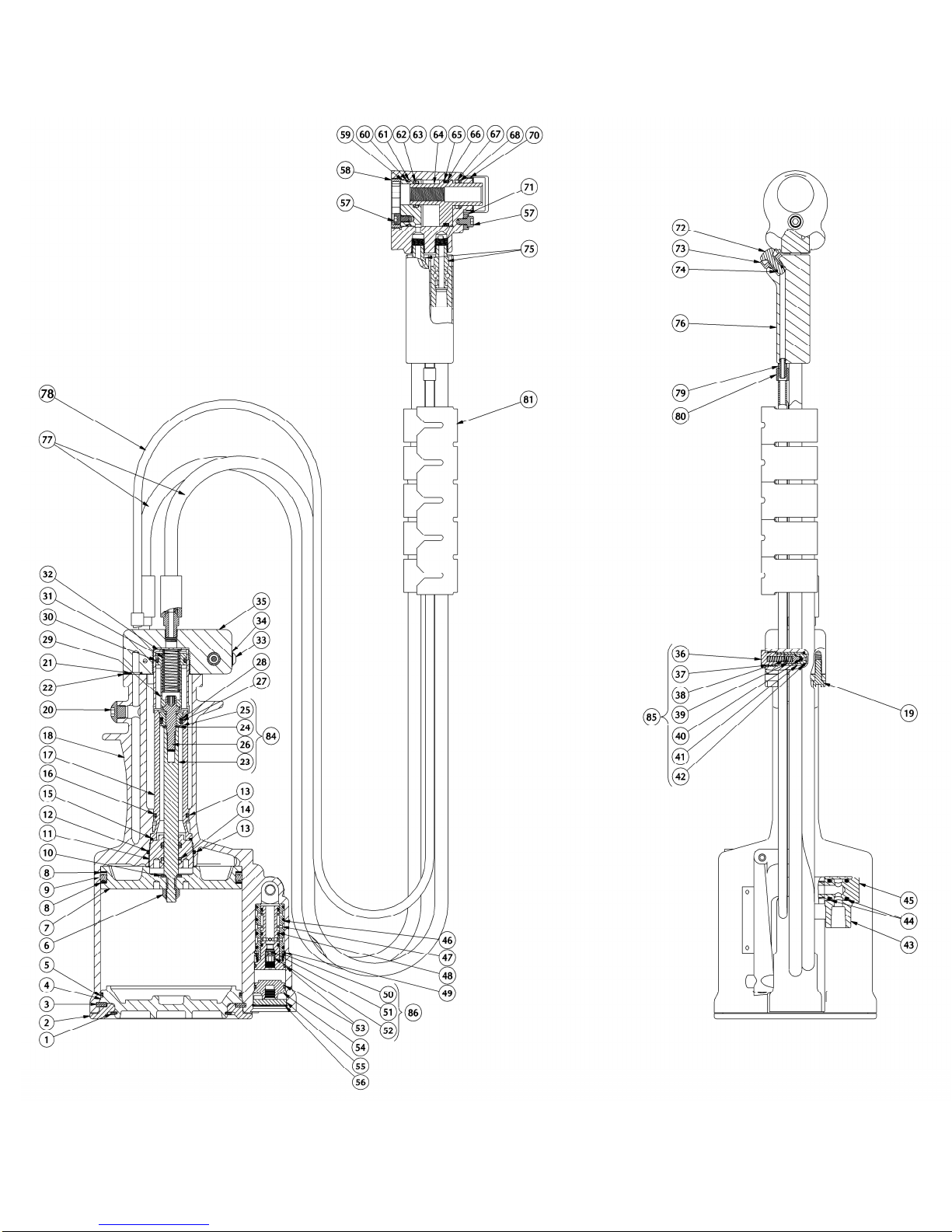
G84-LS CROSS SECTIONAL VIEW
10
G84-LS
EXPLODED
VIEW
11

For more information please contact our Technical Services Department at Tel. 714
-
850
-
6022
Seller warrants the goods conform to applicable specifications and drawings and will be manufactured and inspected according to generally
accepted practices of companies manufacturing industrial or aerospace fasteners. In the event of any breach of the foregoing warranty, Buyer’s
sole remedy shall be to return defective goods (after receiving authorization from Seller) for replacement or refund of the purchase price, at the
Seller’s option. Seller agrees to any freight costs in connection with the return of any defective goods, but any costs relating to removal of the
defective or nonconforming goods or installation of replacement goods shall be Buyer’s responsibility. SELLER’S WARRANTY DOES NOT
APPLY WHEN ANY PHYSICAL OR CHEMICAL CHANGE IN THE FORM OF THE PRODUCT IS MADE BY BUYER.
THE FOREGOING EXPRESS WARRANTY AND REMEDY ARE EXCLUSIVE AND ARE IN LIEU OF ALL OTHER WARRANTIES AND
REMEDIES; ANY IMPLIED WARRANTY AS TO QUALITY, FITNESS FOR PURPOSE, OR MERCHANTABILITY IS HEREBY SPECIFICALLY
DISCLAIMED AND EXCLUDED BY SELLER. THIS WARRANTY IS VOID IF SELLER IS NOT NOTIFIED IN WRITING OF ANY REJECTION OF
THE GOODS WITHIN ONE (1) YEAR AFTER INITIAL USE BY BUYER OF ANY POWER RIVETER OR NINETY (90) DAYS AFTER INITIAL USE
OF ANY OTHER PRODUCT.
Seller shall not be liable under any circumstances for incidental, special or consequential damages arising in whole or in part from any breach by
Seller,
AND SUCH INCIDENTAL, SPECIAL, OR CONSEQUENTIAL DAMAGES ARE HEREBY EXPRESSLY EXCLUDED.
1224 East Warner Ave,
Santa Ana, CA 92705
Tel: 1-714-545-5511
Fax: 1-714-850-6093
www.cherryaerospace.com
© 2007 Cherry Aerospace
Declaration of Conformity
We, Cherry Aerospace, 1224 E. Warner Ave., Santa Ana, CA 92705
declare under our sole responsibility that the product
t yp e G 8 4 - L S
Serial No. ___________________
to which this declaration relates is in conformity with the following standards
EN ISO 12100- parts 1 &2
ISO 8662 part 1
I S O 3 7 4 4
following the provisions of the Machine Directive 2006/42/EC
Santa Ana, CA - date of issue ____________
Original certification and signature on file
WARRANTY
TM-G84-LS
Rev.: F
DCR# 09-1232
Date: 12/1/09
Supplier’s Federal Identification Code: 11815
Other manuals for G84-LS
1
Table of contents
Other Cherry Aerospace Tools manuals

Cherry Aerospace
Cherry Aerospace G84-LS User manual

Cherry Aerospace
Cherry Aerospace H753A-456 User manual

Cherry Aerospace
Cherry Aerospace H828-8MB Instruction Manual

Cherry Aerospace
Cherry Aerospace CherryMAX G744 User manual

Cherry Aerospace
Cherry Aerospace H753A-275NP Instruction Manual

Cherry Aerospace
Cherry Aerospace H83B-6MBU Instruction Manual

Cherry Aerospace
Cherry Aerospace H83HL-6MB Instruction Manual

Cherry Aerospace
Cherry Aerospace H828-6MB Instruction Manual


