TLT-Moto CAN-Switchbox User manual

Instruction manual of the CAN-Switchbox
from serial number (S/N) #600
(OrderCode#4010)
(Ke less-Version)
Are ou looking for a German manual?
Visit our homepage
www.tlt-moto.de
Thank you for choosing a quality product made in Germany y TLT-Moto.
This product has een and will e constantly tested and developed y
engineers and technicians who ride motorcycles themselves.
CAN-Switch ox manual Seite 1 / 12

Please read the instructions and o serve them when mounting and connecting the
CAN-Switch ox.
1. function of the CAN-Switchbox
The CAN-Switch ox is a le to simulate and replace the original handle ar controls
as well as the speedometer on the current Sportster®, Dyna® and Softail® models
with HD-LAN.
This way you are a le to use the push utton fittings, tachometers or foreign
speedometers offered y different manufacturers. It is important that all functions
of the original Harley® version are maintained with our CAN-Switch ox. With
most custom conversions one tries to achieve a CLEAN condition. Here the compact
design of the ox with only 70x50x20mm is very helpful. It can actually e installed
at any point in the motorcycle, prefera ly in the frame triangle ehind the steering
head earing. This would have the advantage of eing directly at the original
connection point of the fittings. The connector can thus e used directly, prefera ly
from the right side.
2. connection
The connection of our ox is not witchcraft, ut should e done y a professional for
warranty reasons alone. All uttons or switches which are installed need to e
connected simply against ground (GND) to the CAN-Switch ox on the appropriate
slot. The outputs of the CAN-Switch ox switch +12 volts. The outputs for indicator
LEDs [R7 - R12] switch ground (GND). Which you can see in the circuit diagram
and the pin assignment.
As power supply for the high-power outputs (supply line [M10]) +12 volts from the
ignition should e used.
For correct function a good connection to vehicle ground is very important,
therefore at least one of the two hexagonal threaded olts should e firmly
connected to ground.
2.1 Pin assignment
The exact pin assignment of the CAN-Switch ox is descri ed in more detail in the
following ta le. The pin assignment is shown in Figure 2.1 and in the following
ta le.
CAN-Switch ox manual Seite 2 / 12
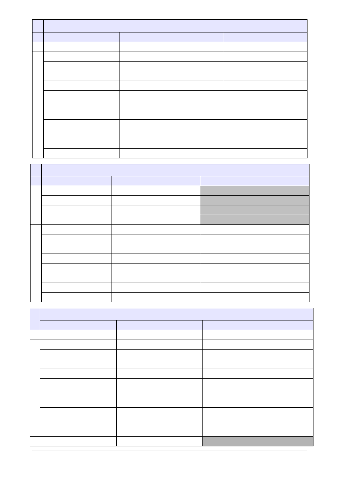
Connector strip left (input)
Pin number
Function
Connection
L1 - GND
Ground (GND)
Button input
L2 - Turn Left
Turn signal left on / off
Push Button Turn Left
L3 - Turn Right
Turn signal right on / off
Push Button Turn Right
L4 - Start
Engine start
Button Start
L5 - Kill/RUN
Ignition on/off (start/stop)
Kill/R N button
L - Clutch
Coupling
Clutch switch
L7 - Break
Brake
Pushbutton brake lever
L8 - High Beam
High beam on / off
High beam button
L9 - Horn
Horn
Pushbutton horn
L10 - Trip
Trip
Pushbutton Trip
L11 - Flash
Headlight flasher
Button flasher
L12 - EMC
Hazard warning lights
Button warning flasher
Connector strip right (low power output)
Pin number
Function
Connection
R1 - GND
Ground (GND)
[22B-1] 2 Black Ground
R2 - +12V
+12 Volt Plus Battery
[22B-1] 1 Red +12V
R3 - CAN L
CAN_Low
[22B-1] 4 green CAN Low
R4 - CAN H
CAN_High
[22B-1] 3 yellow CAN High
R5 - Speed Out
Speedometer Speed to output
output ext. speedometer Speed
R - RPM Out
Speedometer RPM to output
output ext. tachometer RPM
LED outputs
R7 - Turn Left LED
Turn left LED to ground
Only for LED (switched GND)
R8 - Turn Right LED
Turn right LED to ground
Only for LED (switched GND)
R9 - ABS LED
ABS LED to ground
Only for LED (switched GND)
R10 - Neutral LED
Neutral LED to ground
Only for LED (switched GND)
R11 - OIL LED
Oil pressure LED to ground
Only for LED (switched GND)
R12 - HIGH BEAM LED
High beam LED to ground
Only for LED (switched GND)
Middle terminal block (high power output)
Pin number
Function
Connection
M1 - GND
Ground (GND)
Here the mass can
Power outputs
M2 - Turn Left Power
+12V Power Output 36Watt
Output turn signal right
M3 - Turn Right Power
+12V Power Output 36Watt
Output turn signal right
M4 - ABS Power-Ouput
+12V Power Output 36Watt
Output ABS indicator light
M5 - Neutral Power
+12V Power Output 36Watt
Output Neutral indicator light
M - Oil Power-Output
+12V Power Output 36Watt
Output high beam control light
M7 - High Beam Power
+12V Power Output 36Watt
Output oil indicator light
M8 - reserved
M9 - reserved
M10 - +12 Volt Power
+12V input for M2 - M9
Please connect with ignition
M11 - Trip SwitchOut
Original Trip switch Output
M12 - RUN
R N
[22B-2] Energy Stop
CAN-Switch ox manual Seite 3 / 12

Figure 2.1 Pin assignment
2.2 Connection of the CAN-Switchbox
The CAN-Switch oxis connected to the motorcycle with the contacts [M12] (RUN),
[R1] (GND), [R2] (+12V), [R3] (CAN-Low) and [R4] (CAN-High) These signals
are located on the connectors for the original handle ar fittings. A corresponding
set of connectors is availa le from TLT-Moto (see Figure 3.1). If the motorcycle is
not operated, the CAN-Switch ox switches itself off (the Power LED goes out). The
CAN-Switch ox switches itself on when needed.
2.3 Connecting the pushbuttons
As already mentioned, the uttons are connected to the corresponding input of the
CAN-Switch ox. One pole of the utton is connected to the input of the ox and the
other pole to the ground (GND) of the vehicle. You do not have to pay attention to
the polarity of the utton.
Figure 2.3 Connecting the pushbuttons
CAN-Switch ox manual Seite 4 / 12
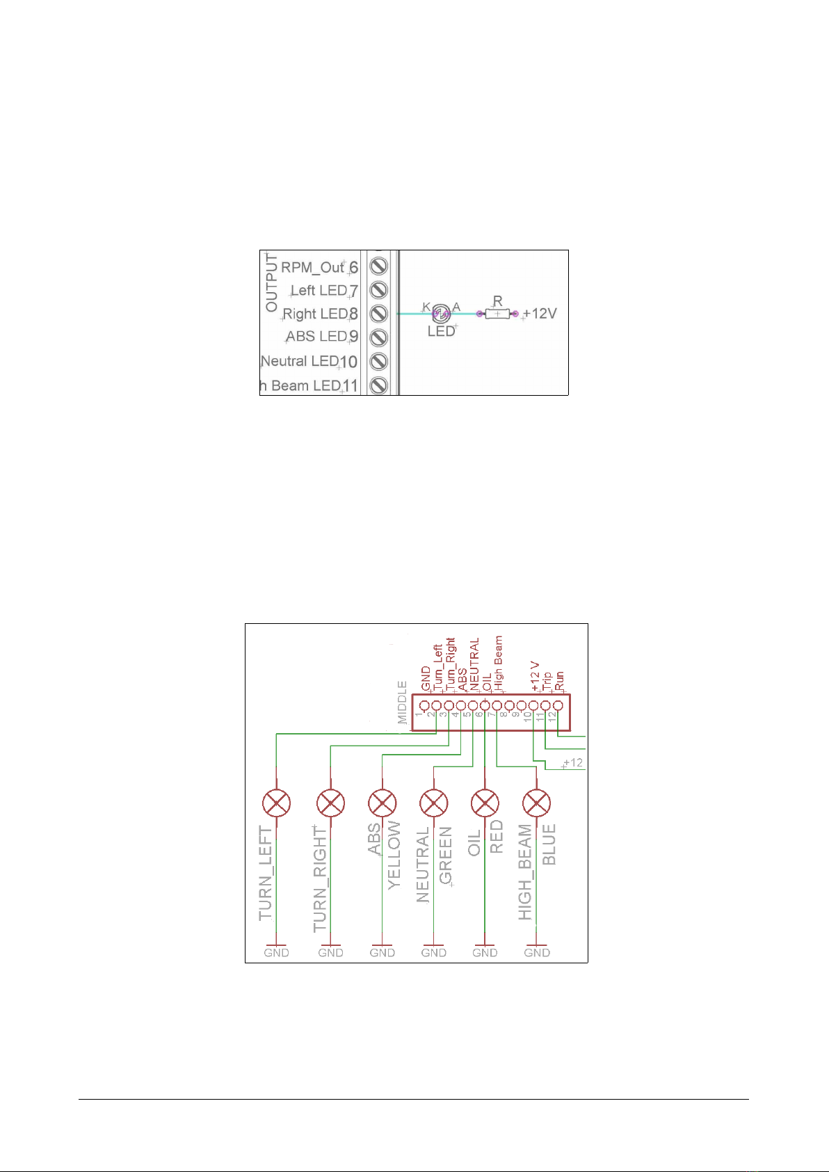
2.4 Connecting the LED indicator ights
The CAN-Switch ox switches ground (GND) for the LED control lamps. These are
the outputs [R7] to [R12]. See also chapter 2.6.
Thus the + pole (anode) of the control LEDs must e connected to +12 volts and the
cathode to the corresponding output of the CAN-Switch ox. The CAN-Switch ox
switches on the GND-signal. With 12 volt LEDs no series resistor is necessary.
Otherwise a series resistor is needed, see figure 2.4. Please make sure that all
outputs [R5 - R12] are not loaded with more than 100 mA.
Figure 2.4 Connection of the LED indicator lights
2.5 Connecting the indicators
The + pole of the turn signals is connected to the corresponding output [M2 + M3]
of the CAN-Switch ox. The other pole must e connected to ground (GND) of the
vehicle. The connection of 12 Volt LED turn signals is possi le without load resistor.
Note that these outputs are supplied y a common lead [M10]. This should e
connected +12Volt from the ignition.
Figure 2.5 Connecting the turn signals and indicator lights
CAN-Switch ox manual Seite 5 / 12

free page
CAN-Switch ox manual Seite 6 / 12

free page
CAN-Switch ox manual Seite 7 / 12
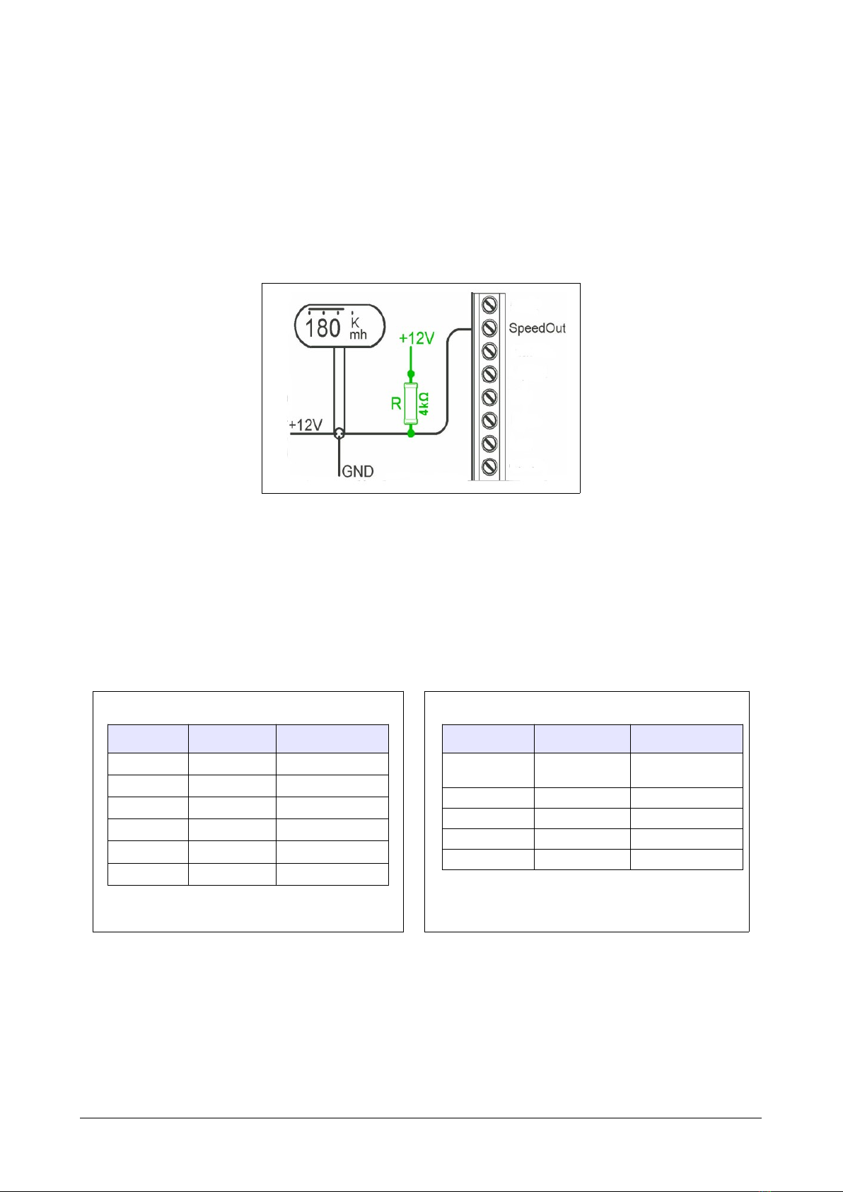
2.6 Connection of a new speedometer or tachometer
e.g. from motogadget®.
The CAN-Switch ox provides a pulse signal for the external tachometer [R5] and
also a pulse signal for a tachometer [R6]. Thus, no pulse generators have to e
installed. The CAN-Switch ox provides a pulsed ground (GND). This signal
corresponds to that of most tachometers in the accessories (e.g. motoscope® or
Chromclassic® from motogadget®). In some cases, the supplied pull-up resistors
must e connected to the operating voltage and the SpeedOut or RPMOut outputs
(see Figure 2.6), so that the tachometer interprets the signal correctly.
Figure 2.6 Connection without resistor or with an approx. 4,7 kΩ pull-up
If the menu utton of the new tachometer should not e operated y an additional
utton, the trip input of the tachometer (e.g. mg-scope-mini the green line) can e
connected to [M11] of the CAN-Switch ox.
There is no pro lem to connect the 6-fold LED ar from Thunder ike or the
motosign-mini.
For example:
Thunderbike 6x LED-Leiste
color function CAN-Switchbox
white turn left R7
gray/pink turn right R8
black abs R9
gray neutral R 0
blue oil R
green high beam R 2
connect brown, yellow, pink, red,
violett, red/blue to switched + 2V
motosign mini (5x LED-Leiste)
color function CAN-Switchbox
red turn left
or right
M2 + M3 via
two diodes
blue abs M4
white neutral M5
brown oil M6
green high beam M7
connect orange, yellow, black and
violett to [M ] or ground
connect switched + 2V to [M 0]
2.7 CAN-Switchbox for rep acing the origina speedometer
If only the original speedometer unit should e replaced, for example the
CAN-Switch ox can e connected in its place as shown in Figure 2.7.
CAN-Switch ox manual Seite 8 / 12

Figure 2.7 Excerpt from the flow chart of a D na® Model 2012
The original speedometer, which is no longer present, is automatically detected y
the CAN-Switch ox furthermore our ox starts to simulate the speedometer. It
sends all necessary signals to the on- oard electronics and the BCM does not detect
any difference to the original version. So there are no error messages and the
motorcycle can e operated with a foreign speedo. Figure 2.7 shows the connector
[39B] of the original speedometer and which wires have to e connected where.
2.8 Specia functions and key combinations
When converting the original handle ar fittings, the num er of controls/ uttons
are usually reduced. Therefore, some uttons have additional functions so that you
can even reproduce all original functions with a total of 6 uttons.
Thus, the following is possible:
Instrument panel-left 3 uttons: turn left, high eam, horn
Instrument panel-right 3 uttons: turn right, KILL/RUN (+Start), trip
Here is a list of the implemented additional functions:
Transport mode: press oth turn-signals- uttons simultaneously
Emergenc lights: with hand rake held, press oth turn- uttons simultaneously
KILL/RUN button: y riefly pressing the KILL/RUN utton you switch etween
KILL and RUN mode. In RUN mode, the ignition is switched
on and the low eam is switched on lights up and the fuel
pump works. In KILL mode, the output LED on the CAN
switch ox flashes very quickly (approx. 4Hz). The
motorcycle switches off the ignition and everything turns off
completely after a while. If the engine has een running
efore, it will stop
Start engine with Kill/RUN: long press the KILL/RUN utton (approx. 2-3 sec.)
simulates pressing the start utton and the engine starts.
Trip/Menu button simulation: If the speedometer has een replaced, the so-
called Menu utton of the new speedometer can e operated
via the CAN-Switch ox. For example just connect the green
line of the mg-scope-mini to the [M11] of the
CAN-Switch ox. By pressing the trip, the menu utton is
pressed if you have an original handle ar fitting.
Attention, this only works with menu uttons after Switch
ground.
CAN-Switch ox manual Seite 9 / 12
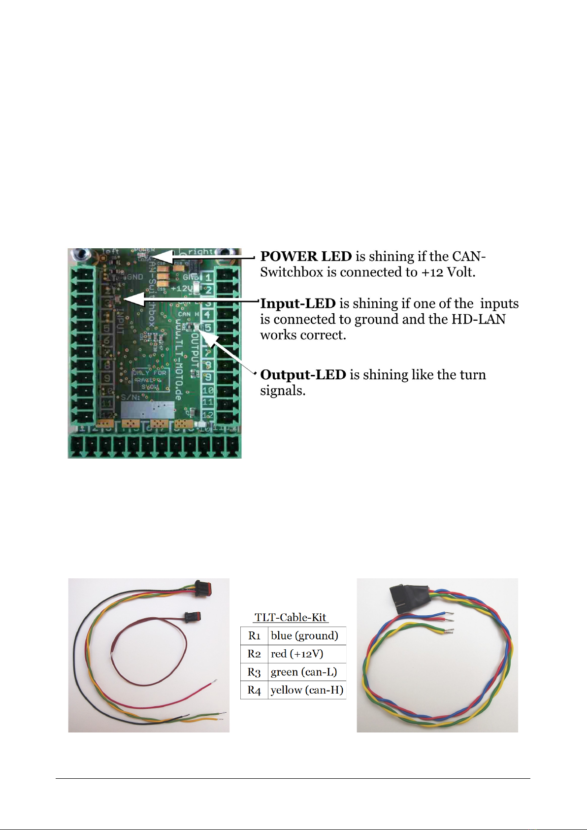
2.9 What do the LEDs of the CAN-Switchbox mean?
The three LEDs on the oard facilitate the connection of the CAN-Switch ox. The
POWER LED is located in the upper part of the oard, it lights up as soon as the
circuit is connected to 12 volts (Figure 2.9).
On the left side of the top of the CAN-Switch ox there is the input LED. It lights up
as soon as one of the numerous inputs is connected to ground, ut only if the ox is
connected to the BCM. This means that the Input-LED does not light up although
for example the Trip-Input is connected to ground, ut the CAN is not or wrongly
connected.
On the right side there is the output LED, which is only on / off alternately in time
with the original turn signal lights. When the turn signal is on, the output LED
flashes very fast and the CAN-Switch ox is in kill/stop mode.
Figure 2.9 The LEDs on the CAN-Switchbox
3 optiona accessories
To facilitate the connection to the existing motorcycle electronics we offer a ca le
connection kit. These kits are optional and must e ordered separately. The
following pictures show the two availa le ca le connection kits for direct connection
to the original, existing HD connectors.
Figure 3.1 Handlebar cable kit [22B] Figure 3.2 Speedometer cable kit [39B]
(Order code #3001) (Order code #3002)
CAN-Switch ox manual Seite 10 / 12

4 Technica data
Length / Width / Depth: 70 mm / 50 mm / 20 mm
Weight: approx. 35 g
Mounting holes: 2 x M3 10 mm deep
Current consumption: approx. 28 mA (logic), stand y approx. 9 µA
Operating voltage: 7 - 18V
Operating temperature: -20° + 80°C
5 Disc aimer
THE CAN SWITCHBOX SHOULD NEVER BE OPENED OR CHANGED, IN THIS EVENT WILL
VOID ANY WARRANTY. TLT-MOTO SHALL NOT BE LIABLE FOR ANY DIRECT, INDIRECT
OR CONSEQUENTIAL DAMAGES OF ANY KIND ARISING OUT OF THE USE, INSTALLATION
OR CONNECTION OF CAN-SWITCHBOX OR DELIVERED EQUIPMENT. INCLUDING, BUT
ALL DAMAGE TO PERSONS AND PROPERTY DAMAGE OF. THE USE IN THE FIELD OF
PUBLIC TRAFFIC IS AT YOUR OWN RISK.
Last but not east
If you have a motorcycle equipped with the CAN-Switch ox, we are looking
forward to a photo of your machine to pu lish it in our gallery
Please email photos to mail@tlt - moto.de.
rev. 4.9
CAN-Switch ox manual Seite 11 / 12
www.tlt-moto.de

Connect:
function color
L1 ground ___________________________________________________
L2 turn left-switch ___________________________________________________
L3 turn right-switch ___________________________________________________
L4 start-switch ___________________________________________________
L5 kill/run-switch ___________________________________________________
L6 clutch-switch ___________________________________________________
L7 reak-switch ___________________________________________________
L8 high eam-switch ___________________________________________________
L9 horn-switch ___________________________________________________
L10 trip-switch ___________________________________________________
L11 flashlight-switch ___________________________________________________
L12 emergency-switch ___________________________________________________
function color
R1 ground ___________________________________________________
R2 +12 Volt ___________________________________________________
R3 hd-can low ___________________________________________________
R4 hd-can high ___________________________________________________
R5 speed-out ___________________________________________________
R6 rpm-out ___________________________________________________
R7 turn left led ___________________________________________________
R8 turn right led ___________________________________________________
R9 a s led ___________________________________________________
R10 neutral led ___________________________________________________
R11 oil led ___________________________________________________
R12 high eam led ___________________________________________________
function color
M1 ground ___________________________________________________
M2 turn left power out ___________________________________________________
M3 turn right power out ___________________________________________________
M4 a s power output ___________________________________________________
M5 power output ___________________________________________________
M6 power output ___________________________________________________
M7 power output ___________________________________________________
M8 reserved ___________________________________________________
M9 reserved ___________________________________________________
M10 +12Volt power input ___________________________________________________
M11 trip switch output ___________________________________________________
M12 RUN-control ___________________________________________________
CAN-Switch ox manual Seite 12 / 12
This manual suits for next models
1
Table of contents


