3
CONTENTS
A. GE ERAL
A. GE ERALA. GE ERAL
A. GE ERAL
................................
................................................................
................................................................
................................................................
............................................
........................
............
4
44
4
1. SAFETY I FORMATIO 4
B. THE HELMET
B. THE HELMETB. THE HELMET
B. THE HELMET
................................
................................................................
................................................................
................................................................
......................................
............
......
5
55
5
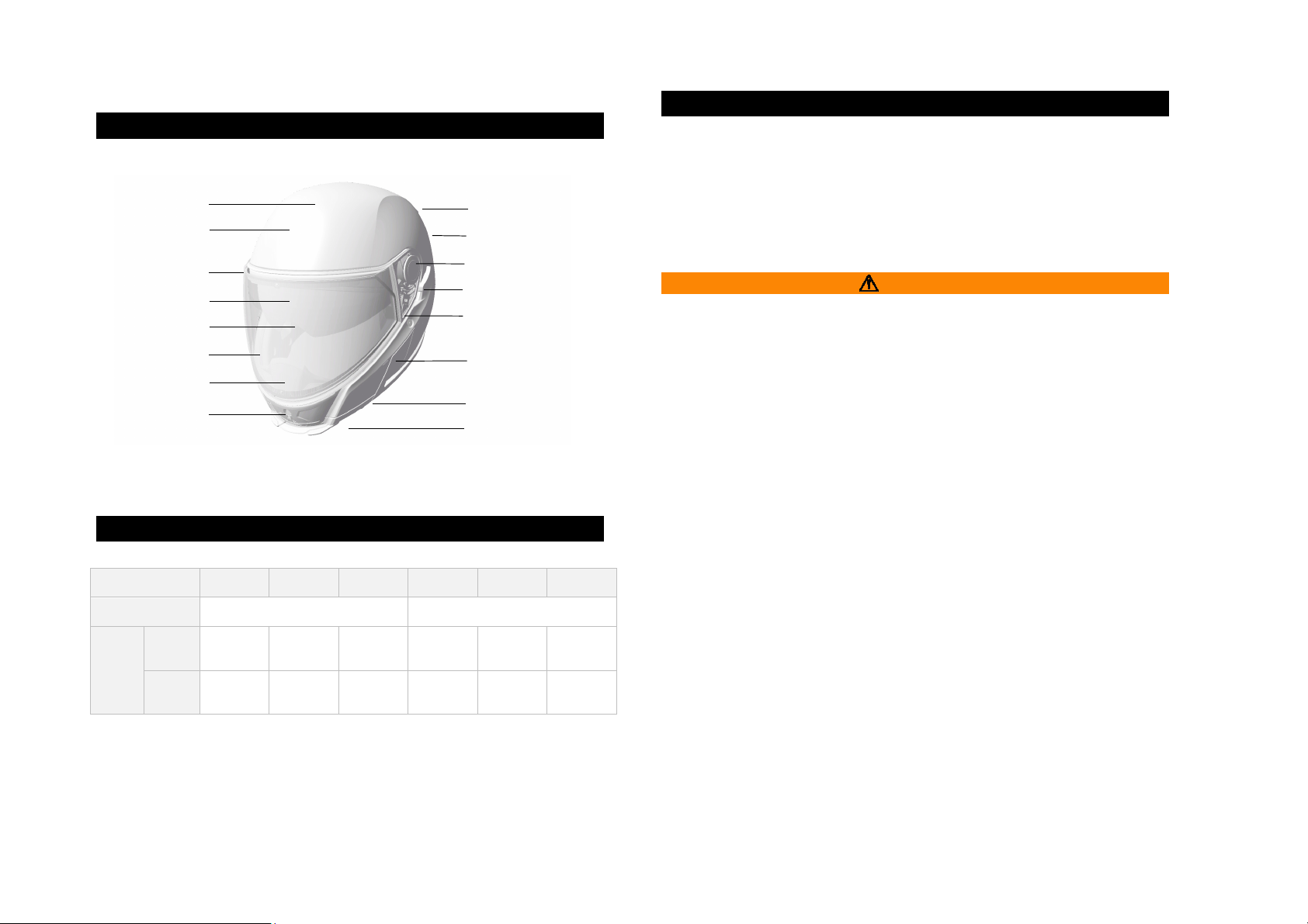
1. A ATOMY OF THE HELMET 5
2. HELMET SIZI G 5
3. AEROACOUSTICS 5
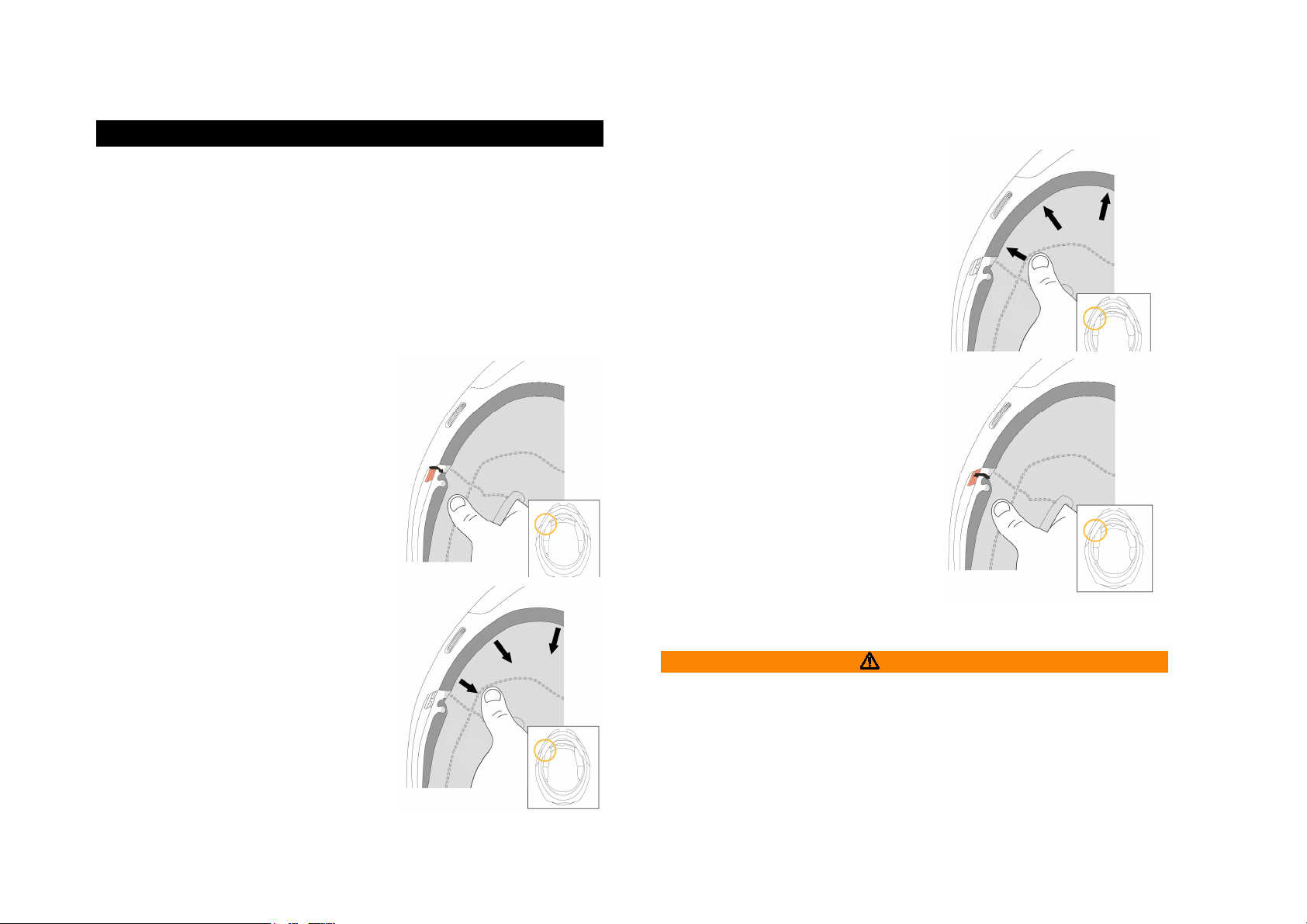
4. PROTECTIVE COLLAR 6
5. MICROMETRIC CHI STRAP 7
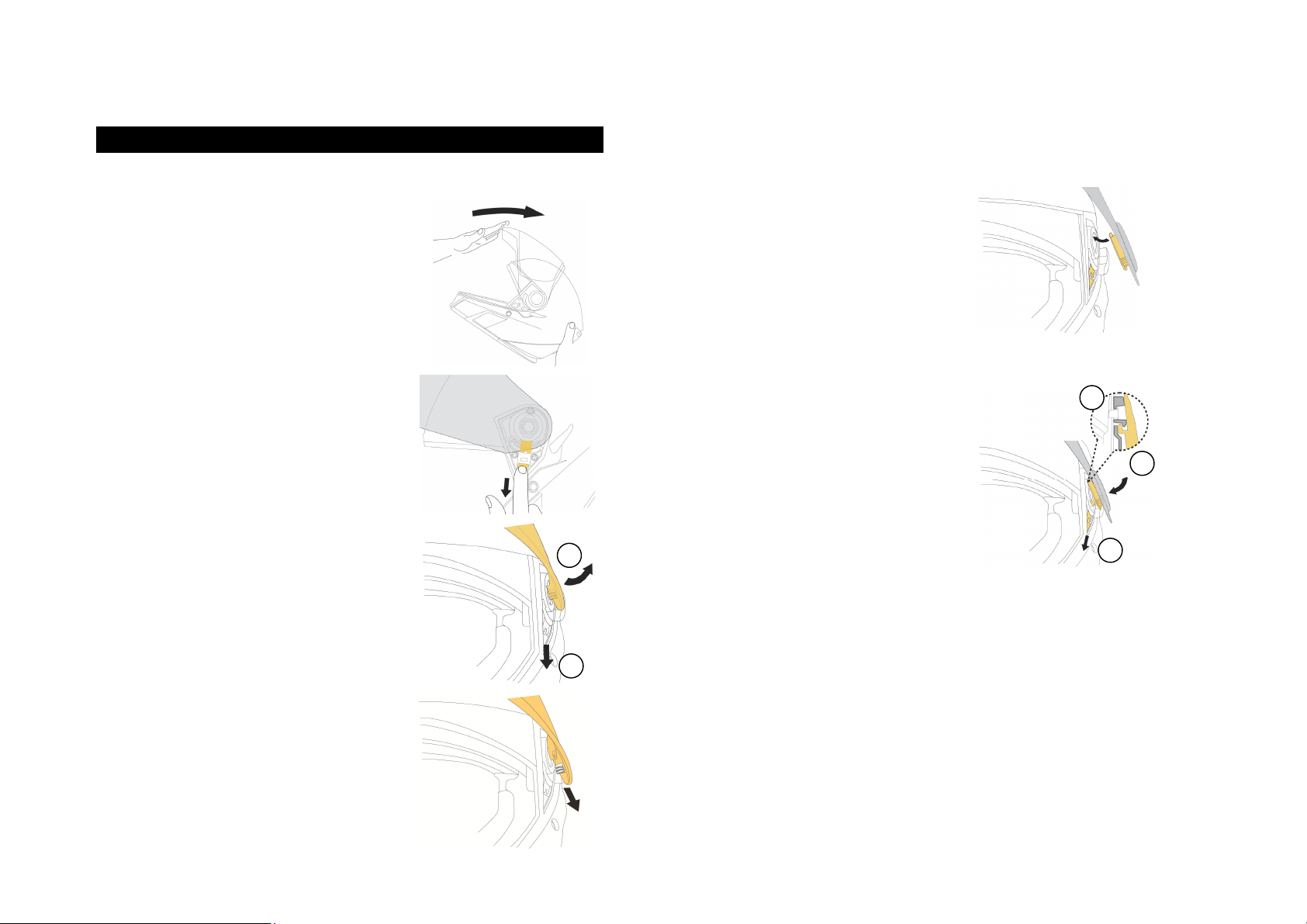
6. FACE SHIELD 8
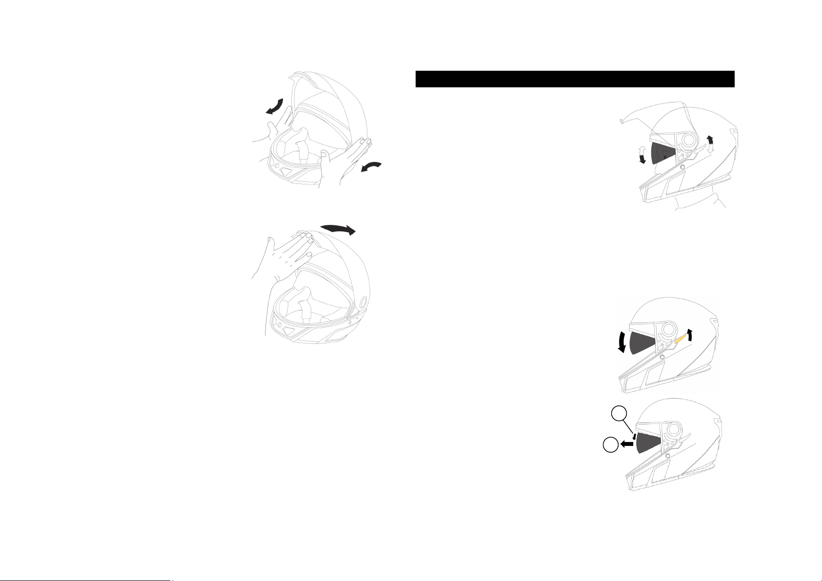
7. SU VISOR 9
8. MAG ETIC CO ECTOR 10
9. REAR LIGHT 11
10. FACE SHIELD MECHA ISM 12
11. OISE CO TROL SYSTEM 13
12. I ER LI ER 13
13. VE TILATIO SYSTEM 15
14. BREATH GUARD 15
15. REMOTE CO TROL 16
C. FIT & USAGE
C. FIT & USAGEC. FIT & USAGE
C. FIT & USAGE
................................
................................................................
................................................................
................................................................
.....................................
..........
.....
17
1717
17
1. HOW TO PUT THE HELMET O 17
2. PROPER FIT 17
3. PUT THE HELMET OFF 18
4. OPERATI G I STRUCTIO S 18
5. COMMU ICATIO SYSTEM I STALLATIO 20
D. BEFORE EVERY RIDE
D. BEFORE EVERY RIDED. BEFORE EVERY RIDE
D. BEFORE EVERY RIDE
................................
................................................................
.......................................................
..............................................
.......................
21
2121
21
1. CHECKI G THE HELMET 21
2. CHECKI G THE CHI STRAP 21
3. CHECKI G THE FACE SHIELD A D SU VISOR 21
4. CHECKI G THE MAG ETIC CO ECTOR 21
E. OTHER IMPORTA T I FORMATIO
E. OTHER IMPORTA T I FORMATIOE. OTHER IMPORTA T I FORMATIO
E. OTHER IMPORTA T I FORMATIO
................................
................................................................
..................................
....
..
22
2222
22
1. MODIFICATIO S / ACCESSORIES 22
2. FROSTBITE 22
F. CARE A D MAI TE A CE
F. CARE A D MAI TE A CEF. CARE A D MAI TE A CE
F. CARE A D MAI TE A CE
................................
................................................................
................................................
................................
................
23
2323
23
1. SHELL CLEA I G 23
2. I TERIOR CLEA I G 23
3. OUTER SURFACE OF THE FACE SHIELD 23
4. HEATI G LE S 23
5. ELECTRICAL CO ECTIO S 23
6. SU VISOR 24
7. HELMET I SPECTIO 24
8. HELMET STORAGE 24
G. TROUBLESHOOTI G GUIDE
G. TROUBLESHOOTI G GUIDEG. TROUBLESHOOTI G GUIDE
G. TROUBLESHOOTI G GUIDE
................................
................................................................
.............................................
..........................
.............
25
2525
25
H. ACCESSORIES A D SPARE PARTS
H. ACCESSORIES A D SPARE PARTSH. ACCESSORIES A D SPARE PARTS
H. ACCESSORIES A D SPARE PARTS
................................
................................................................
..................................
....
..
26
2626
26
1. ACCESSORIES 27
2. REPLACEME T PARTS 27
3. LED UTILITY LIGHT I STALLATIO 29
4. LED UTILITY LIGHT BATTERIES REMPLACEME T 30
I. BRP SERVICE
I. BRP SERVICEI. BRP SERVICE
I. BRP SERVICE
................................
................................................................
................................................................
................................................................
.....................................
..........
.....
31
3131
31
1. REPAIR SERVICE 31
2. WARRA TY 31
J. HOW TO CO TACT US
J. HOW TO CO TACT USJ. HOW TO CO TACT US
J. HOW TO CO TACT US
................................
................................................................
.......................................................
..............................................
.......................
31
3131
31