TLV QuickTrap FS3 User manual

172-65128MA-11 (FS3/FS5/FS5H + BD2) 10 March 2017
Free Float Steam Trap
QuickTrap®
FS3 / FS5 / FS5H
Trap Unit
S3 / S5 / S5H
(For Connector Body F46)
Copyright © 2017 by TLV CO., LTD.
All rights reserved

172-65128MA-11 (FS3/FS5/FS5H + BD2) 10 Mar 2017
1
Contents
Introduction .............................................................................1
Safety Considerations.............................................................2
Checking the Piping................................................................4
Specifications..........................................................................5
Compatibility............................................................................5
Configuration...........................................................................6
Installation...............................................................................7
Maintenance............................................................................9
Disassembly/Reassembly.....................................................10
Instructions for Plug/Holder Disassembly and Reassembly......12
Troubleshooting ....................................................................13
Product Warranty ..................................................................14
Options..................................................................................15
Introduction
Thank you for purchasing the free float steam trap.
This product has been thoroughly inspected before being shipped from the
factory. When the product is delivered, before doing anything else, check the
specifications and external appearance to make sure nothing is out of the
ordinary. Also be sure to read this manual carefully before use and follow the
instructions to be sure of using the product properly.
This free float steam trap uses a universal flange, a precision-polished float and
three-point support for the valve body. With no hinges or levers, the trap
automatically continuously discharges condensate, preventing it from collecting.
The three-point seating for the valve body supports the precision-polished float
securely at three points and ensures a high degree of sealing for even minute
quantities of condensate. The universal flange allows the trap to be installed in
either horizontal or vertical piping. This flexibility greatly reduces the time
required for installation and removal, as compared to conventional steam traps,
and also facilitates repair and maintenance operations.
If detailed instructions for special order specifications or options not contained in
this manual are required, please contact for full details.
This instruction manual is intended for use with the model(s) listed on the front
cover. It is necessary not only for installation, but for subsequent maintenance,
disassembly/reassembly and troubleshooting. Please keep it in a safe place for
future reference.
172-65128MA-11 (FS3/FS5/FS5H + BD2) 10 Mar 2017
2
Safety Considerations
•Read this section carefully before use and be sure to follow the instructions.
•Installation, inspection, maintenance, repairs, disassembly, adjustment and
valve opening/closing should be carried out only by trained maintenance
personnel.
•The precautions listed in this manual are designed to ensure safety and
prevent equipment damage and personal injury. For situations that may
occur as a result of erroneous handling, three different types of cautionary
items are used to indicate the degree of urgency and the scale of potential
damage and danger: DANGER, WARNING and CAUTION.
•The three types of cautionary items above are very important for safety: be
sure to observe all of them as they relate to installation, use, maintenance
and repair. Furthermore, TLV accepts no responsibility for any accidents or
damage occurring as a result of failure to observe these precautions.
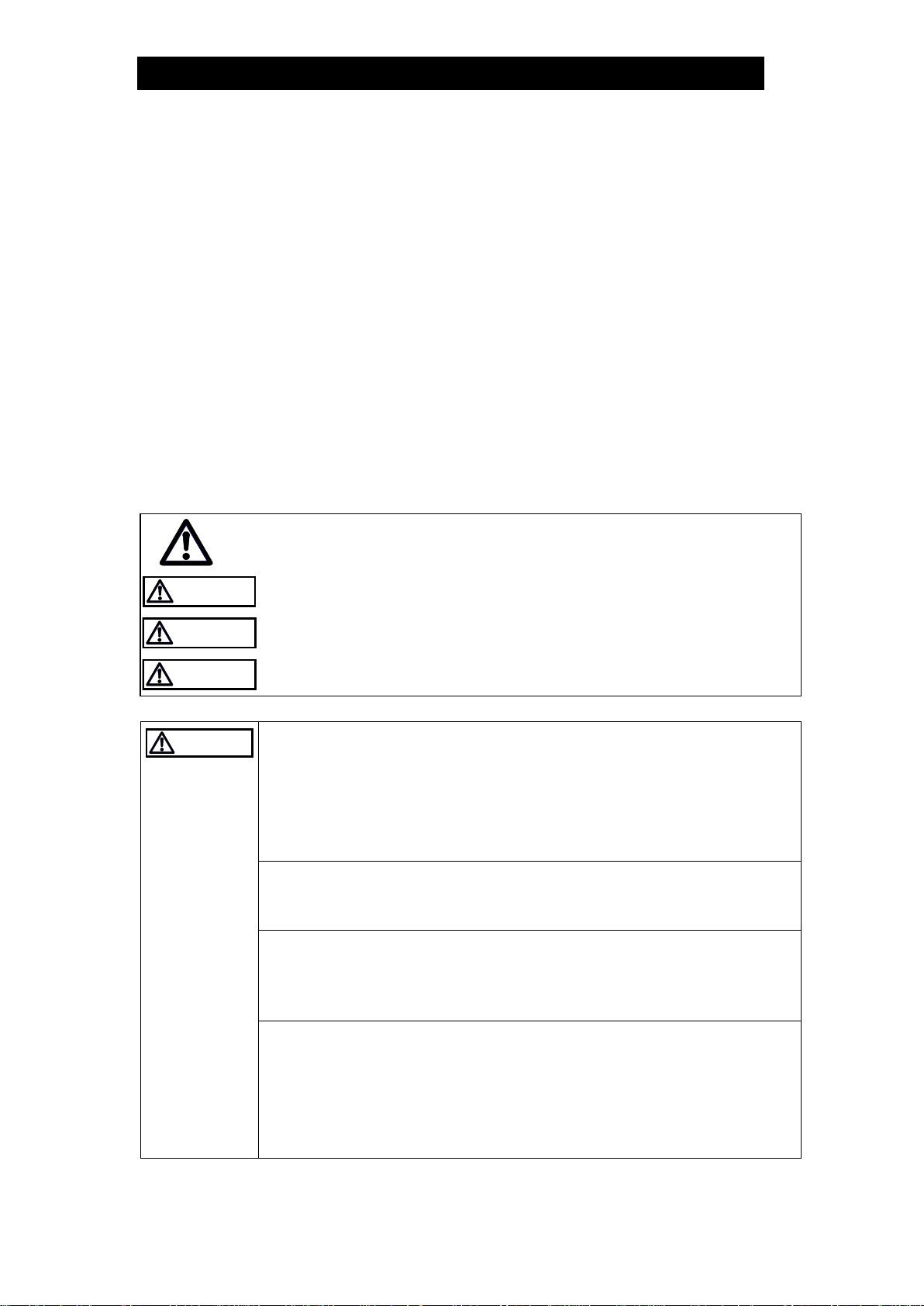
Symbols
Indicates a DANGER, WARNING or CAUTION item.
DANGER
Indicates an urgent situation which poses a threat of death or serious
injury
WARNING
Indicates that there is a potential threat of death or serious injury
CAUTION
Indicates that there is a possibility of injury or equipment / product
damage
CAUTION
Install properly and DO NOT use this product outside the
recommended operating pressure, temperature and other
specification ranges.
Improper use may result in such hazards as damage to the product
or malfunctions that may lead to serious accidents. Local regulations
may restrict the use of this product to below the conditions quoted.
DO NOT use this product in excess of the maximum operating
pressure differential.
Such use could make discharge impossible (blocked).
Take measures to prevent people from coming into direct
contact with product outlets.
Failure to do so may result in burns or other injury from the
discharge of fluids.
When disassembling or removing the product, wait until the
internal pressure equals atmospheric pressure and the surface
of the product has cooled to room temperature.
Disassembling or removing the product when it is hot or under
pressure may lead to discharge of fluids, causing burns, other
injuries or damage.
Safety considerations continued on next page.
172-65128MA-11 (FS3/FS5/FS5H + BD2) 10 Mar 2017
3
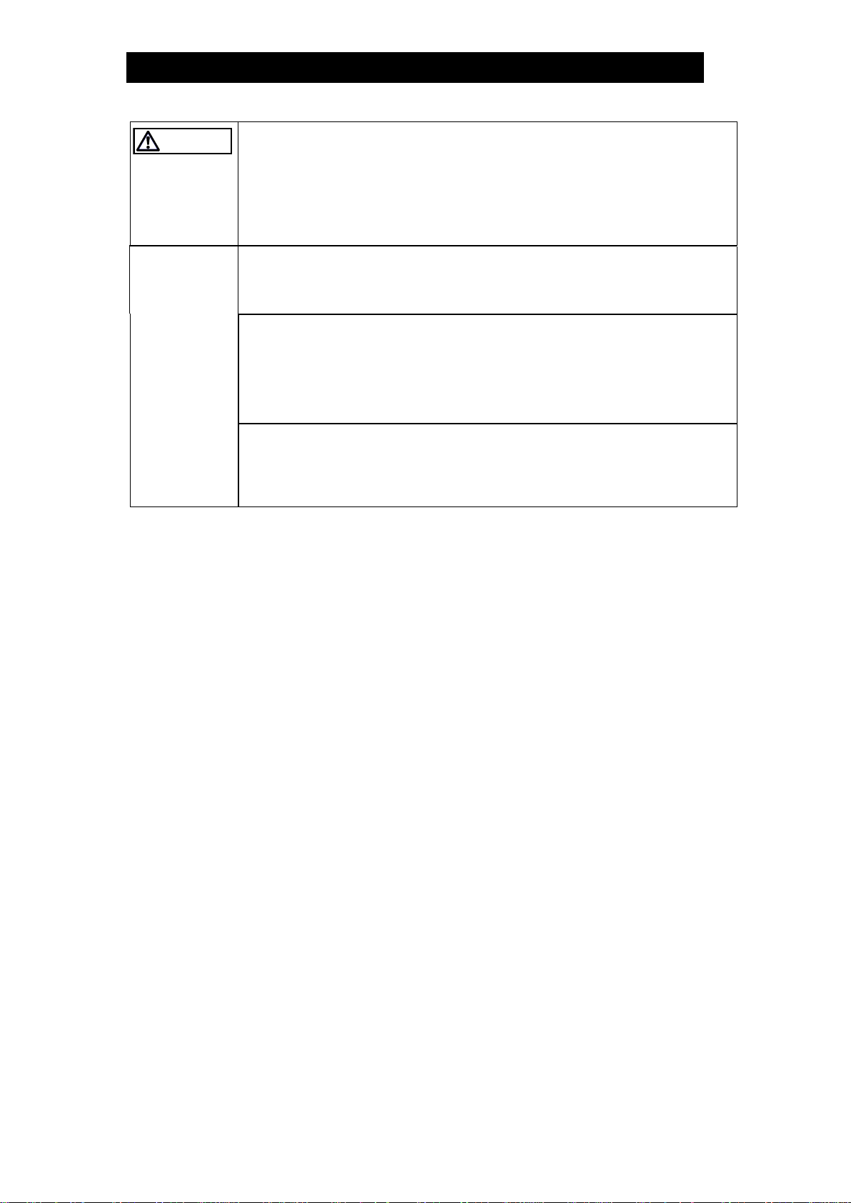
CAUTION
Be sure to use only the recommended components when
repairing the product, and NEVER attempt to modify the
product in any way.
Failure to observe these precautions may result in damage to the
product and burns or other injury due to malfunction or the discharge
of fluids.
Use only under conditions in which no freeze-up will occur.
Freezing may damage the product, leading to fluid discharge, which
may cause burns or other injury.
The pressure and temperature values displayed on the
nameplate of the connector body are the values for the
connector body itself and not for the entire trap.
Improper use may result in such hazards as damage to the product
or malfunctions that may lead to serious accidents.
Use only under conditions in which no water hammer will
occur.
The impact of water hammer may damage the product, leading to
fluid discharge, which may cause burns or other injury.

172-65128MA-11 (FS3/FS5/FS5H + BD2) 10 Mar 2017
4
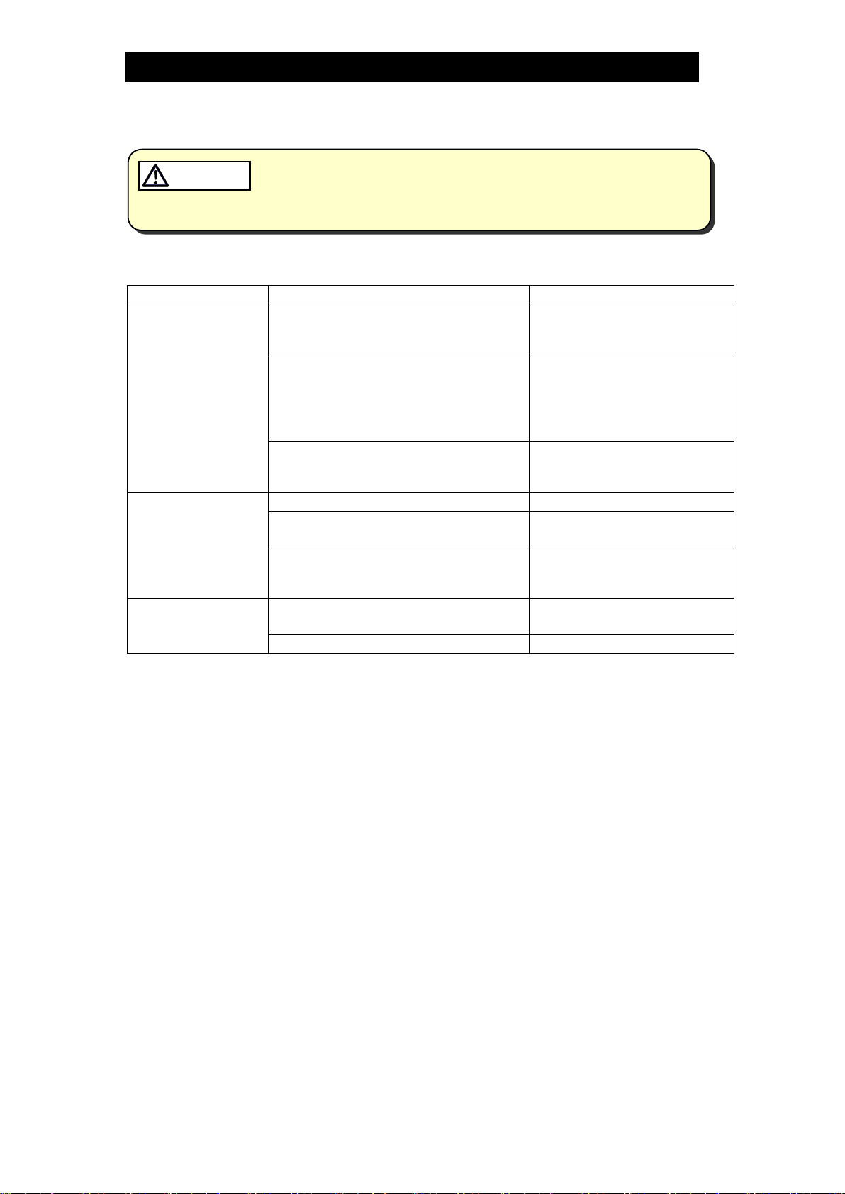
Checking the Piping
Use only under conditions in which no water hammer will occur. The
impact of water hammer may damage the product, leading to fluid
discharge, which may cause burns or other injury.
CAUTION
Check to make sure that the pipes to be connected to the trap have been installed
properly.
1. Is the pipe diameter suitable?
2. Has sufficient space been secured for maintenance?
3. Have isolation valves been installed at the inlet and outlet? If the outlet is subject to
back pressure, has a check valve (TLV-CK) been installed?
4. Is the inlet pipe as short as possible, with as few bends as possible, and installed
so the liquid will flow naturally down into the trap?
5. Has the piping work been done correctly, as shown in the figures below?
Requirement
Correct
Incorrect
Install catchpot with the
proper diameter.
Diameter is too small.
Make sure the flow of
condensate is not
obstructed.
Diameter is too small and inlet
protrudes into pipe interior.
To prevent rust and scale
from flowing into the trap,
the inlet pipe should be
connected 25 – 50 mm (1
– 2 in) above the base of
the T-pipe.
Rust and scale flow into the
trap with the condensate.
When installing on the
blind end, make sure the
flow of condensate is not
obstructed.
Condensate collects in the
pipe.
172-65128MA-11 (FS3/FS5/FS5H + BD2) 10 Mar 2017
5
Specifications
Install properly and DO NOT use this product outside the recommended
operating pressure, temperature and other specification ranges.
Improper use may result in such hazards as damage to the product or
malfunctions which may lead to serious accidents. Local regulations
may restrict the use of this product to below the conditions quoted.
CAUTION
DO NOT use this product in excess of the maximum operating pressure
differential; such use could make discharge impossible (blocked).
CAUTION
Use only under conditions in which no freeze-up will occur. Freezing
may damage the product, leading to fluid discharge, which may cause
burns or other injury.
CAUTION
The pressure and temperature values displayed on the nameplate of the
connector body are the values for the connector body itself and not for
the entire trap. Improper use may result in such hazards as damage to
the product or malfunctions that may lead to serious accidents.
CAUTION
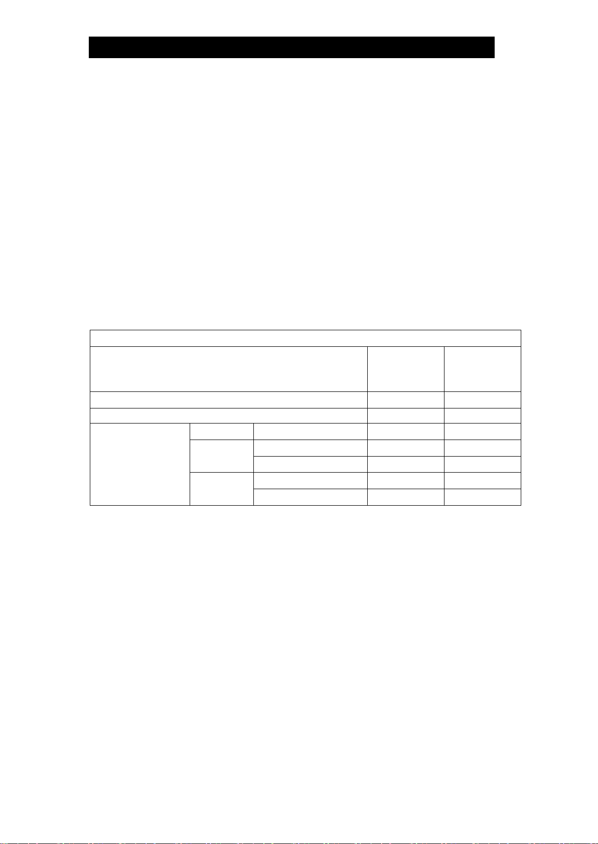
Refer to the product nameplates on the trap unit AND on the connector body for
detailed specifications.
The specifications displayed on each nameplate apply only to the unit on which it is
mounted. When a trap unit is installed on a connector unit and the PMA/TMA and/or
PMO/TMO values displayed on the two nameplates differ, the specifications for the
assembled product are restricted to the lower values.
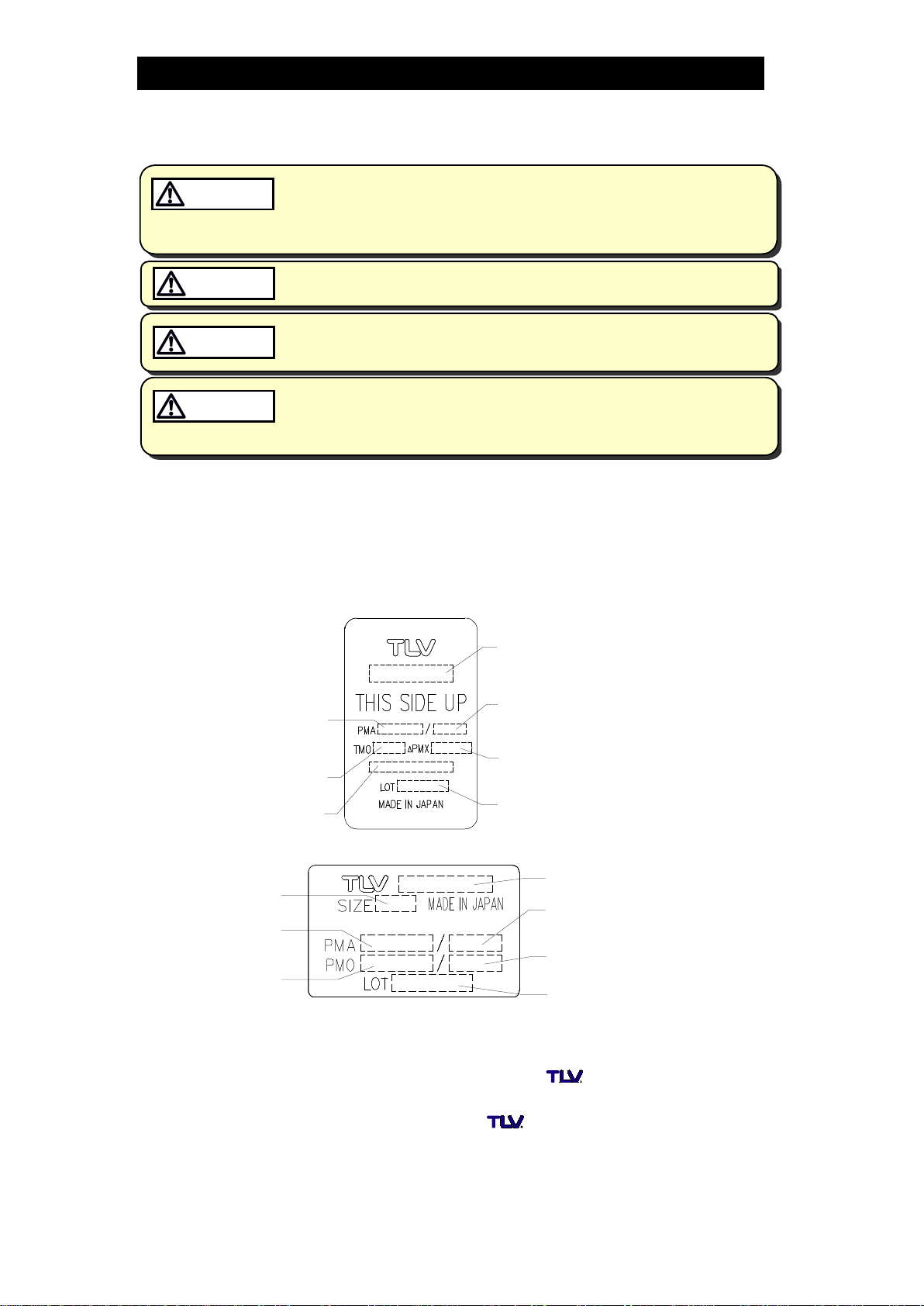
Trap Unit
*Maximum
allowable
pressure (PMA)
and maximum
allowable
temperature
(TMA) are
PRESSURE
SHELL DESIGN
CONDITIONS,
NOT
OPERATING
CONDITIONS.
**
Valve No. is
displayed for
products with
options. This
item is omitted
from the
nameplate
when there are
no options.
Maximum Allowable
Temperature (TMA)*
Maximum Allowable
Pressure*
Model
Valve No.
Maximum Operating
Temperature
Maximum Differential
Pressure
Production Lot No.
Connector Unit (mounted only on F46)
Model
Maximum Allowable
Temperature (TMA)*
Maximum Operating
Temperature (TMO)
Nominal Diameter
Maximum Allowable
Pressure*
Production Lot No.
Maximum Operating
Pressure
Compatibility
•The FS3/FS5/FS5H QuickTrap series employs a connector unit (F46) and is
not compatible with QuickTrap models using connector unit F46J.
•Trap unit (S3/S5/S5H) is compatible with Trap Stations (V1/V2/V1P/V2P
Series) and can be installed on those trap stations or connector unit (F32).
The connector unit name is embossed on the connector body.

172-65128MA-11 (FS3/FS5/FS5H + BD2) 10 Mar 2017
6
Configuration
No.
Name
M
T
C
1
Trap Body
2
Inner Cover
3
Float
4
Orifice
5
Float Guide
6
Air Vent Strip
7
Connector Joint
8
Trap Screen
9
Nameplate
10
UP Seal*
11
Connector Flange
12
Snap Ring
13
Inner/Outer Connector Gaskets
14
Connector Bolt
15
Connector Body
16
Screen
17
Screen Holder Gasket
18
Screen Holder
19
Connector Nameplate
M: Maintenance Kit
T: Trap Unit (S3/S5/S5H)
C: Connector Unit (F46)
*Not always included
NOTE: Replacement parts for former connector body F32 differ from those for F46. When you
order replacement parts, please include the steam trap model name, size, connection
type and also the connector unit name.
172-65128MA-11 (FS3/FS5/FS5H + BD2) 10 Mar 2017
7
Installation
Install properly and DO NOT use this product outside the recommended
operating pressure, temperature and other specification ranges.
Improper use may result in such hazards as damage to the product or
malfunctions which may lead to serious accidents. Local regulations
may restrict the use of this product to below the conditions quoted.
CAUTION
Take measures to prevent people from coming into direct contact with
product outlets. Failure to do so may result in burns or other injury from
the discharge of fluids.
CAUTION
Installation, inspection, maintenance, repairs, disassembly, adjustment and valve
opening/closing should be carried out only by trained maintenance personnel.
1. Before installation, be sure to remove all protective seals.
2. Before installing the product, blow out the inlet piping to remove any piping scraps,
dirt and oil. Close the inlet valve after blowdown.
3. Install the product so the arrow on the body is pointing in the direction of condensate
flow.
4. The connector body has no restrictions on installation orientation except for the
following conditions: the universal flange face (for connecting to the trap unit) must
be in the vertical plane, and the trap unit must be installed with the nameplate facing
upwards.
5. The trap unit must be installed with the nameplate facing upward, and should be
inclined no more than 5° in any plane. Use the two connector bolts to adjust the
angle of the trap unit.
6. Install a condensate outlet valve and outlet piping.
7. Open the inlet and outlet valves and check to make sure that the product functions
properly.
If there is a problem, determine the cause using the “Troubleshooting” section in this
manual.
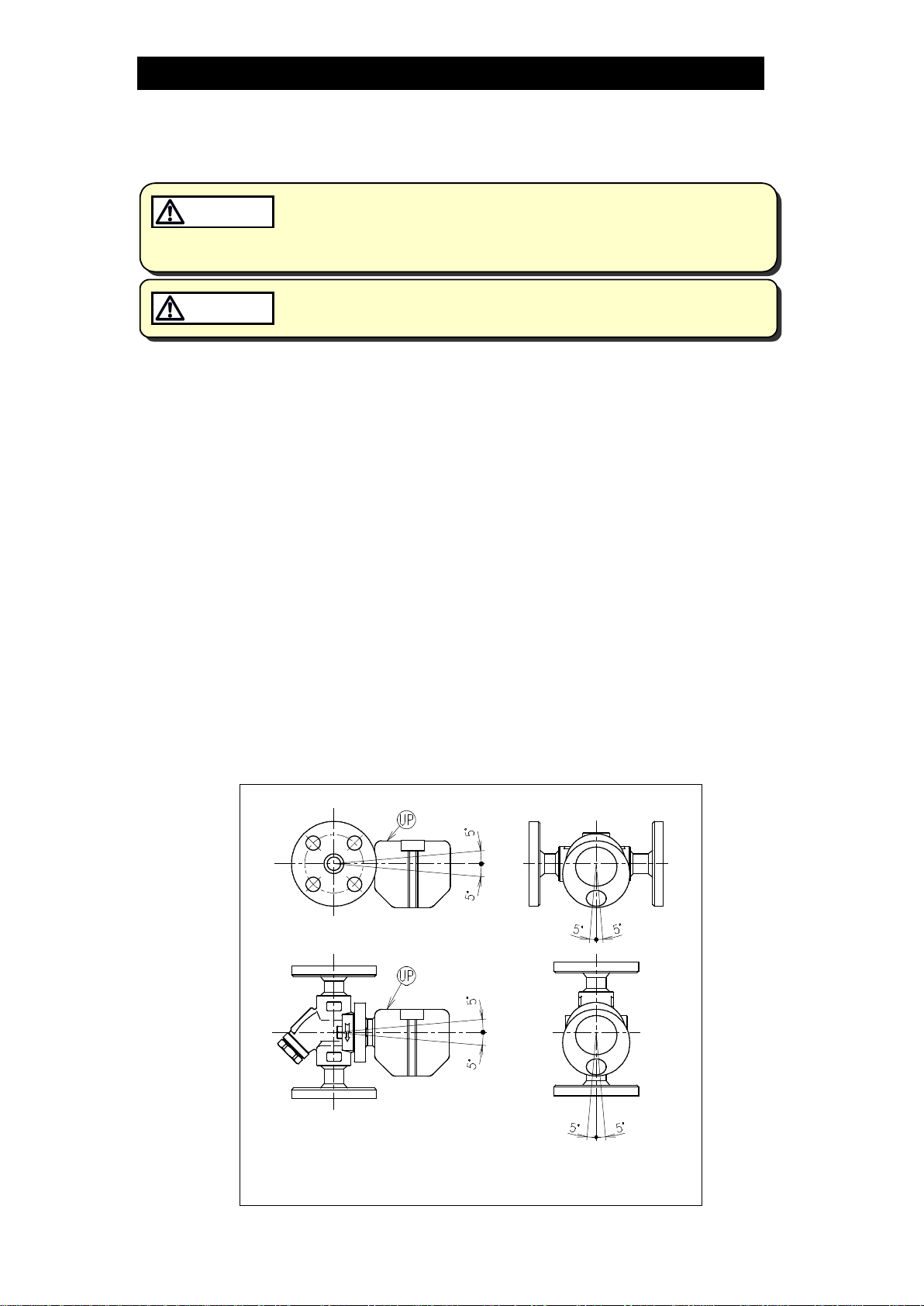
Tolerance Angle for Installation - 5°
Install with the nameplate facing upwards and with the arrow on
the connector body pointing in the direction of condensate flow.
(UP seal: Not always included)
172-65128MA-11 (FS3/FS5/FS5H + BD2) 10 Mar 2017
8
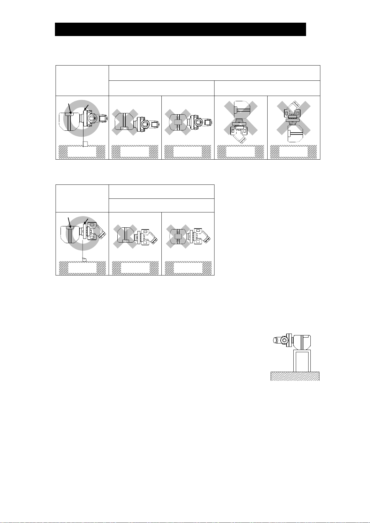
Installation Examples: Horizontal Piping
Correct Incorrect
Nameplate not facing upwards
Universal Connector Flange not in
the vertical plane
GroundGround
GroundGround
GroundGround
GroundGround
GroundGround
Installation Examples: Vertical Piping
Correct Incorrect
Nameplate not facing upwards
GroundGround
GroundGround
GroundGround
Note for FS5/FS5H with Screwed Connection:
When products with screwed connections are installed on
horizontal piping, there is a danger that the weight of the trap unit
will cause the connector body to rotate on the pipe beyond the
allowable angle of inclination preventing proper trap operation. To
prevent this, tighten the screws securely. In cases where the
product is affected by vibrations or by external contact, it is
recommended that the trap unit should be supported to prevent
rotation (sample support shown to the right).
Connector
Flange
Nameplate
Connector
Flange
Nameplate

172-65128MA-11 (FS3/FS5/FS5H + BD2) 10 Mar 2017
9
Maintenance
Take measures to prevent people from coming into direct contact with
product outlets. Failure to do so may result in burns or other injury from
the discharge of fluids.
CAUTION
Be sure to use only the recommended components when repairing the
product, and NEVER attempt to modify the product in any way. Failure to
observe these precautions may result in damage to the product or burns
or other injury due to malfunction or the discharge of fluids.
CAUTION
Operational Check
A visual inspection of the following items should be done on a daily basis to determine
whether the trap is operating properly or has failed. Periodically (at least biannually) the
operation should also be checked by using diagnostic equipment such as a
stethoscope, thermometer, TLV Pocket TrapMan or TLV TrapMan.
If the trap should fail, it may cause damage to piping and equipment, resulting in faulty
or low quality products or losses due to steam leakage.
Normal : Condensate is discharged continuously, together with flash steam,
and the sound of flow can be heard. If there is very little
condensate, there is almost no sound of flow.
Blocked
(Discharge Impossible)
: No condensate is discharged. The trap is quiet and makes no
noise, and the surface temperature of the trap is low.
Blowing : Live steam continually flows from the outlet and there is a
continuous metallic sound.
Steam Leakage : Live steam is discharged through the trap outlet together with
condensate, accompanied by a high-pitched sound.
(When conducting a visual inspection, flash steam is sometimes mistaken for steam leakage.
For this reason, the use of a steam trap diagnostic instrument [such as TLV TrapMan if
appropriate] in conjunction with the visual inspection is highly recommended.)
Parts Inspection
When parts have been removed, or during periodic inspections, use the following table
to inspect the parts and replace any that are found to be defective.
Procedure
Gaskets: Check for warping or scratches
Screens: Check for clogging or corrosion
Trap Unit, Connector Body: check inside bodies for rust and scale
Flash Steam
Live Steam Leakage
Clear, slightly
bluish jet
White jet
containing
water droplets
172-65128MA-11 (FS3/FS5/FS5H + BD2) 10 Mar 2017
10
Disassembly/Reassembly
When disassembling or removing the product, wait until the internal
pressure equals atmospheric pressure and the surface of the product
has cooled to room temperature. Disassembling or removing the
product when it is hot or under pressure may lead to discharge of fluids,
causing burns, other injuries or damage.
CAUTION
Use the following procedures to remove components. Use the same procedures in
reverse to reassemble. (Installation, inspection, maintenance, repairs, disassembly,
adjustment and valve opening/closing should be carried out only by trained
maintenance personnel.)
Detaching/Reattaching the Trap Unit
Part
During Disassembly
During Reassembly
Connector Bolts
Remove with a socket
wrench
Consult the table of tightening torques and
tighten to the proper torque
Trap Unit
Remove the trap unit
Follow the special instructions below
(See Fig. A)
Connector
Gaskets
Remove with a scraper and
clean the connector flange
with a soft tool.
Replace with new gaskets; to facilitate
assembly and prevent loosening of the
gaskets, apply a small amount of adhesive at
120º intervals around the outer edge of the
gaskets
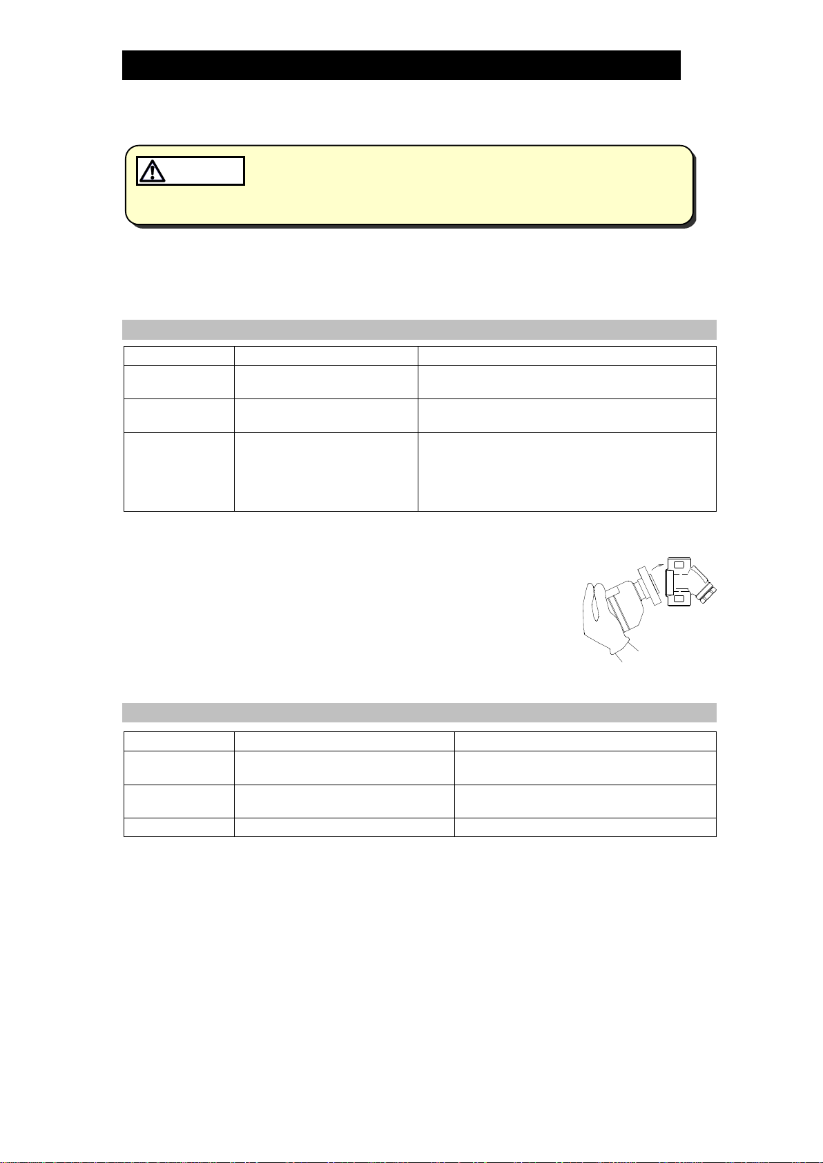
Attaching the Trap Unit to the Connector Body
1.
If attaching a new trap unit, be sure to remove the protective
cap from the connector flange. Be careful not to drop the
gaskets when removing the cap.
2.
Grasp the end of the trap unit and align its gasket housing with
the indentation on the connector body. Be sure to have the
nameplate facing upwards.
3.
Once aligned, insert and finger tighten the connector bolts.
Verify that the trap unit is within the allowable inclination.
Figure A
Disassembly/Reassembly of Components Inside the Connector Body
Part
During Disassembly
During Reassembly
Screen Holder
Remove with a socket wrench
Consult the table of tightening torques
and tighten to the proper torque
Screen Holder
Gasket
Remove the gasket
Replace with a new gasket only if warped
or damaged
Screen
Remove with needle-nose pliers
Insert securely into the connector body
172-65128MA-11 (FS3/FS5/FS5H + BD2) 10 Mar 2017
11
Table of Tightening Torques
Part Name
Torque
Distance Across Flats
N⋅m
(lbf·ft)
mm
(in)
Connector Bolt
39
(28)
14
(9/16)
Screen Holder (when F46 is used)
100
(73)
30
(13/16)
Screen
Holder
(when
F32 is
used)
Flanged
15 – 25 mm (1/2– 1 in)
60
(44)
22
(7/8)
Screwed
15 ⋅20 mm (1/2⋅3/4in)
60
(44)
22
(7/8)
25 mm (1 in)
150
(110)
38
(11/2)
Socket
Welded
15 ⋅20 mm (1/2⋅3/4in)
60
(44)
22
(7/8)
25 mm (1 in)
150
(110)
38
(11/2)
NOTE:
-Coat all threaded portions with anti-seize.
-If drawings or other special documentation were supplied for the
product, any torque given there takes precedence over values
shown here.
(1 N⋅m ≈10 kg⋅cm)
Screen Holders for Connector Units F32 and F46 can be used only with their respective
connector body.
When disassembling and reassembling the components, make sure the correct connector unit
(F32 or F46) is used. The type of connector unit can be identified by the name embossed on its
body.
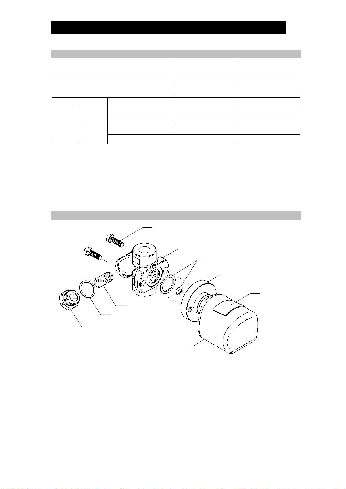
Exploded View
Connector Body (C)
Nameplate (T)
Inner / Outer
Connector Gaskets (T)
Screen (C)
Screen Holder (C)
Connector Flange (T)
Screen Holder Gasket (C)
Trap Body (T)
Connector Bolts (T)
(T) Trap Unit
(C) Connector Unit
172-65128MA-11 (FS3/FS5/FS5H + BD2) 10 Mar 2017
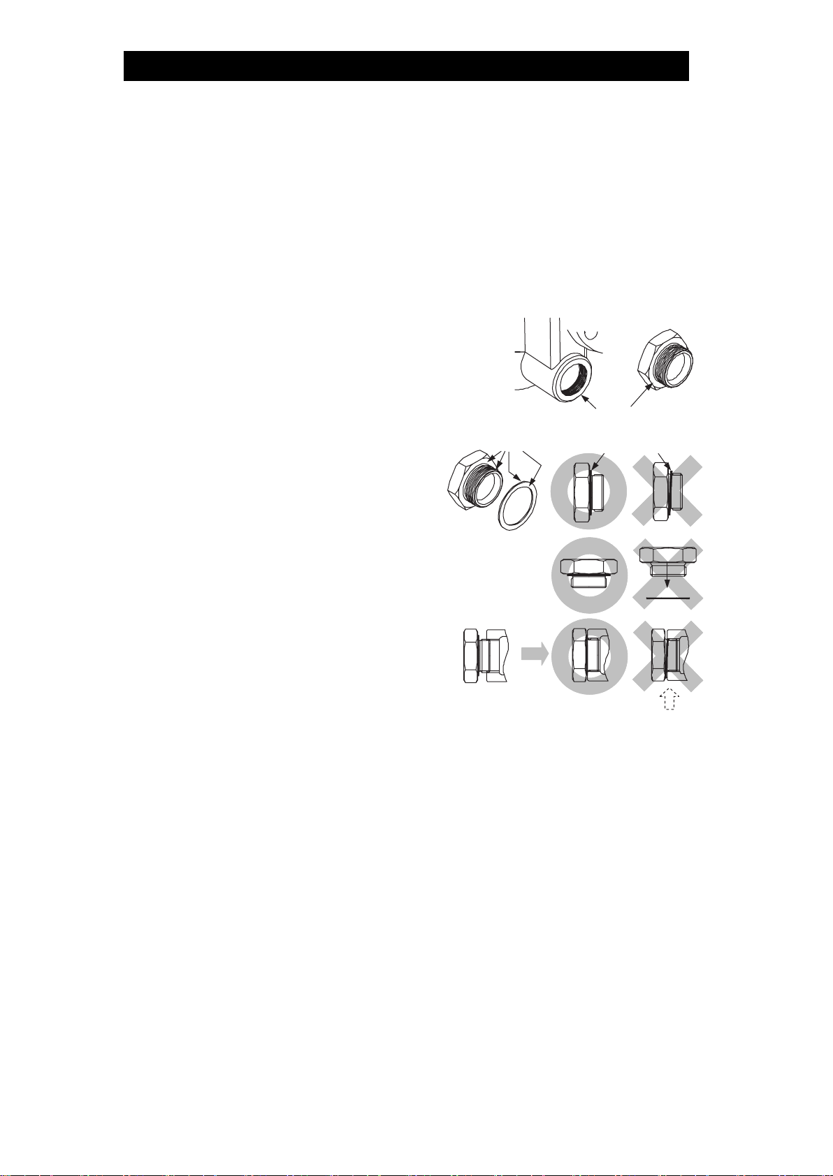
12
Do not pinch gasket
in thread recesses
Coat with anti-seize
Gasket Surface
n
o
Gasket
Instructions for Plug/Holder Disassembly and Reassembly
The seal on the threaded plugs/holders found on TLV products is formed by a flat metal
gasket. There are various installation orientations for the gaskets, such as horizontal,
diagonal and downward, and the gasket may be pinched in the thread recesses during
assembly.
Instructions for Disassembly and Reassembly
①Remove the plug/holder using a tool
of the specified size (distance across
flats).
②The gasket should not be reused. Be
sure to replace it with a new gasket.
③Clean the gasket surfaces of the
plug/holder and the product body using
a rag and/or cleaning agents, then
check to make sure the surfaces are
not scratched or deformed.
④Coat both the gasket surface of the
plug/holder and the threads of the
plug/holder with anti-seize, then
press the gasket onto the center of
the gasket surface of the plug/holder,
making sure the anti-seize affixes the
gasket tightly to the plug/holder.
Check to make sure the gasket is not
caught in the recesses of the threads.
⑤Hold the plug/holder upside down to
make sure that the anti-seize makes
the gasket stick to the plug/holder
even when the plug/holder is held upside down.
⑥Screw the plug/holder by hand into the product body while making sure that the
gasket remains tightly affixed to the center of the gasket surface of the plug/holder.
Make sure the entire gasket is making contact with the gasket surface of the
product body. It is important at this point to make sure the gasket is not pinched in
the thread recesses of the plug/holder.
⑦Tighten the plug/holder to the proper torque.
⑧Next, begin the supply of steam and check to make sure there is no leakage from
the part just tightened. If there is leakage, immediately close the inlet valve and, if
there is a bypass valve, take the necessary steps to release any residual pressure.
After the surface of the product cools to room temperature, repeat the procedure
beginning from step .
172-65128MA-11 (FS3/FS5/FS5H + BD2) 10 Mar 2017
13
Troubleshooting
When disassembling or removing the product, wait until the internal
pressure equals atmospheric pressure and the surface of the product
has cooled to room temperature. Disassembling or removing the
product when it is hot or under pressure may lead to discharge of fluids,
causing burns, other injuries or damage.
CAUTION
If the product fails to operate properly, use the following table to locate the cause and
remedy.
Problem
Cause
Remedy
No condensate is
discharged (blocked)
or discharge is poor
The screen or inlet/outlet channels on
the connector body are clogged with
rust and scale
Clean
The trap operating pressure exceeds
the maximum specified pressure, or
whether there is insufficient pressure
differential between the trap inlet and
outlet
Compare specifications and
actual operating conditions
Steam-locking has occurred
Perform a bypass blowdown
or close the trap inlet valve
and allow the trap to cool
Steam is discharged
or leaks from the
outlet
(blowing)
(steam leakage)
Improper installation orientation
Correct the installation
Excessive trap vibration
Lengthen the inlet piping and
fasten it securely
Water hammer has occurred
Examine for problems that
can cause water hammer and
correct the piping
Steam is leaking
from a place other
than the outlet
The gaskets have deterioration or
damage
Replace with new gaskets
Improper tightening torque was used
Tighten to the proper torque
NOTE: S3/S5/S5H steam trap units are of all-welded, single unit construction, so they cannot be
repaired. If parts need replacement, refer to the parts list in this manual and select the
appropriate kit/unit for replacement parts. Parts are only available as a part of the
kits/units shown.

172-65128MA-11 (FS3/FS5/FS5H + BD2) 10 Mar 2017
14
Product Warranty
1. Warranty Period
One year following product delivery.
2. Warranty Coverage
TLV CO., LTD. warrants this product to the original purchaser to be free from
defective materials and workmanship. Under this warranty, the product will
be repaired or replaced at our option, without charge for parts or labor.
3. This product warranty will not apply to cosmetic defects, nor to any product
whose exterior has been damaged or defaced; nor does it apply in the
following cases:
1) Malfunctions due to improper installation, use, handling, etc., by
other than TLV CO., LTD. authorized service representatives.
2) Malfunctions due to dirt, scale, rust, etc.
3) Malfunctions due to improper disassembly and reassembly, or
inadequate inspection and maintenance by other than TLV CO.,
LTD. authorized service representatives.
4) Malfunctions due to disasters or forces of nature.
5) Accidents or malfunctions due to any other cause beyond the
control of TLV CO., LTD.
4. Under no circumstances will TLV CO., LTD. be liable for consequential
economic loss damage or consequential damage to property.
* * * * * * *
For Service or Technical Assistance:
Contact your representative or your regional office.
Manufacturer
881 Nagasuna, Noguchi
Kakogawa, Hyogo 675-8511 JAPAN
Tel: 81–(0)79–427–1800

172-65128MA-11 (FS3/FS5/FS5H + BD2) 10 Mar 2017
15
Options
With Blowdown Valve (TLV BD2)
Always wear eye protection and heat-resistant gloves when operating
the blowdown valve. Failure to do so may result in burns or other injury.
CAUTION
When operating the blowdown valve, stand to the side well clear of the
outlet to avoid contact with internal fluids that will be discharged.
Operate the valve slowly and surely, taking care to avoid the area from
which internal fluids are discharged and any fluids deflected off piping
or the ground etc. Failure to do so may result in burns or other injury.
CAUTION
Do not tighten the BD2 valve or the BD2 valve seat in excess of the
appropriate tightening torque. Over-tightening may cause breakage to
threaded portions, which may cause burns, other injuries or damage.
CAUTION
Do not excessively loosen the BD2 valve when opening the blowdown
valve. The valve stopper pin installed to prevent the BD2 valve from
being removed may break and internal pressure may result in the BD2
valve being blown off, leading to injuries, damage and fluid discharge,
causing burns.
CAUTION
Configuration
Screen Holder Gasket
BD2 Valve Seat
(Screen Holder)
Screen
Valve Stopper Pin
BD2 Valve Discharge Hole
TLV Blowdown Valve: BD2
The BD2 Blowdown Valve, installed in the screen area of the connector body, uses the
trap’s internal pressure to blow any condensate, steam, dirt or scale accumulated
around the screen area out to atmosphere.
172-65128MA-11 (FS3/FS5/FS5H + BD2) 10 Mar 2017
16
BD2 Blowdown Valve Operation
1. The BD2 valve is in the closed position when the BD2 is shipped from the factory.
Before attempting to operate the BD2, reconfirm that the BD2 valve is still in the closed
position. Locate the blow outlet and, during operation, stand to the side and well clear
of it, as the jet of condensate or steam could cause burns.
2. Remain in the area the entire time the BD2 valve is in the open position. Before
opening the BD2 valve, grip the BD2 valve seat with a wrench and hold firmly in place
so that it will not rotate when the BD2 valve is loosened. Grip the BD2 valve with
another wrench and slowly loosen. Condensate and steam will discharge from the
blow outlet in a jet stream. Be careful not to loosen the BD2 valve so far that it
becomes removed from the BD2 valve seat. (If the valve stopper pin becomes
damaged, large quantities of steam will be discharged in a jet stream.)
3. Close the BD2 valve until the flow of fluid completely stops. If the flow of fluid does
not stop, re-open the BD2 valve (as in step “2”) to blow out any scale or dirt that may
be caught in the BD2. Re-tighten the BD2 valve until the flow of fluid stops
completely.
Tightening Torques and Distance Across Flats
Part Name Torque Distance
Across Flats
N⋅m
(lbf⋅ft)
mm
(in)
BD2 Valve
30
(22)
17
(21/32)
BD2 Valve Seat (Screen Holder) (when F46 is used)
100
(73)
30
(13/16)
BD2 Valve Seat
(Screen Holder)
(when F32 is used)
Flanged
15 – 25 mm
(1/2– 1in)
60
(44)
22
(7/8)
Screwed
15 ⋅20 mm
(1/2, 3/4 in)
60
(44)
22
(7/8)
25 mm
(1 in)
150
(110)
38
(11/2)
Socket
Welded
15 ⋅20 mm
(1/2, 3/4 in)
60
(44)
22
(7/8)
25 mm
(1in)
150
(110)
38
(11/2)
NOTE: Avoid the use of excessive tightening torques, as threaded parts
may become damaged.
(1 N⋅m ≈10 kg⋅cm)
This manual suits for next models
5
Table of contents
Other TLV Plumbing Product manuals


Popular Plumbing Product manuals by other brands

Lemeks
Lemeks Palmako FR42-3327 Assembly, installation and maintenance manual

Elkay
Elkay Hi-Arc LKD2448BH Specifications

Sterling Plumbing
Sterling Plumbing INTRIGUE 72040100 Specifications

Hans Grohe
Hans Grohe Shower Mixer 96429000 Service

American Standard
American Standard Reliant+ Lavatory Faucets 2385.R installation instructions

Anzzi
Anzzi KF-AZ035 installation manual


