TLV JH7.2R-X User manual

172-65457MA-02 (JH7.2R-X) 14 July 2015
Free Float Steam Trap with X-element
JH7.2R-X
Copyright © 2015 by TLV CO., LTD.
All rights reserved
ISO 9001/ ISO 14001
Manufacturer
Kakogawa, Japan
is approved by LRQA LTD. to ISO 9001/14001

172-65457MA-02 (JH7.2R-X) 14 Jul 2015
1
Contents
Introduction........................................................................1
Safety Considerations .......................................................2
Checking the Piping ..........................................................4
Operation...........................................................................5
Specifications....................................................................6
Configuration.....................................................................6
Installation.........................................................................7
Maintenance......................................................................8
Disassembly / Reassembly...............................................9
Instructions for Plug / Holder Disassembly and Reassembly
.12
Troubleshooting...............................................................13
Product Warranty ............................................................14
Options............................................................................15
Introduction
Thank you for purchasing the Free Float Steam Trap.
This product has been thoroughly inspected before being shipped from the factory. When
the product is delivered, before doing anything else, check the specifications and
external appearance to make sure nothing is out of the ordinary. Also be sure to read this
manual carefully before use and follow the instructions to be sure of using the product
properly.
This free float steam trap employs a hinge-less and lever-less free float to rapidly,
automatically and continuously discharge the inflowing condensate that is continuously
generated inside the equipment, thus preventing the accumulation of condensate and
thereby improving the heat transfer efficiency of the equipment.
This steam trap is also of a revolutionary design featuring an integral air vent that
employs a high-performance X-element. The X-element is very sensitive to changes in
temperature, and responds with great accuracy. As a result, air and the large quantities
of condensate created immediately after the start-up of operation are quickly discharged,
thereby greatly reducing start-up time and also proving useful in valve operation (bypass
blowdown) labor-saving.
The X-element is also sensitive to hot air during operation, responding quickly and thus
preventing the occurrence of air binding.
These features make this free float steam trap ideally suited for use on process systems
and equipment (steam-using equipment), and it is especially well-suited for removing
condensate from equipment used for batch operations, which often experience entrained
air during operation.
If detailed instructions for special order specifications or options not contained in this
manual are required, please contact for full details.
This instruction manual is intended for use with the model(s) listed on the front cover. It is
necessary not only for installation but for subsequent maintenance, disassembly/reassembly
and troubleshooting. Please keep it in a safe place for future reference.
172-65457MA-02 (JH7.2R-X) 14 Jul 2015
2
Safety Considerations
•Read this section carefully before use and be sure to follow the instructions.
•Installation, inspection, maintenance, repairs, disassembly, adjustment and valve
opening/closing should be carried out only by trained maintenance personnel.
•The precautions listed in this manual are designed to ensure safety and prevent
equipment damage and personal injury. For situations that may occur as a result of
erroneous handling, three different types of cautionary items are used to indicate
the degree of urgency and the scale of potential damage and danger: DANGER,
WARNING and CAUTION.
•The three types of cautionary items above are very important for safety: be sure to
observe all of them as they relate to installation, use, maintenance, and repair.
Furthermore, TLV accepts no responsibility for any accidents or damage occurring
as a result of failure to observe these precautions.
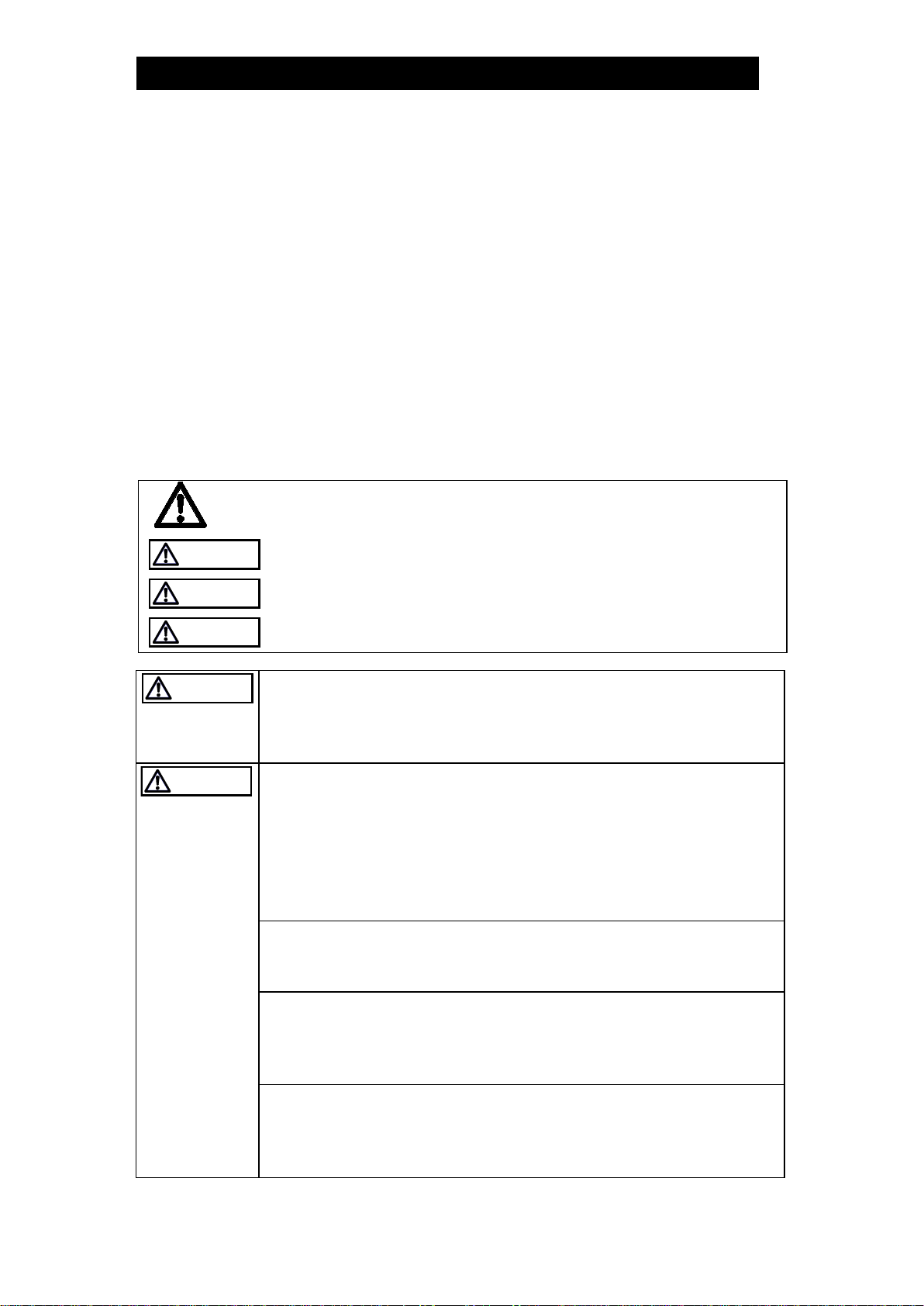
Symbols
Indicates a DANGER, WARNING or CAUTION item.
DANGER
Indicates an urgent situation which poses a threat of death or
serious injury
WARNING
Indicates that there is a potential threat of death or serious injury
CAUTION
Indicates that there is a possibility of injury or equipment / product
damage
WARNING
NEVER apply direct heat to the float.
The float may explode due to increased internal pressure, causing
accidents leading to serious injury or damage to property and
equipment.
CAUTION
Install properly and DO NOT use this product outside the
recommended operating pressure, temperature and other
specification ranges.
Improper use may result in such hazards as damage to the product
or malfunctions that may lead to serious accidents. Local
regulations may restrict the use of this product to below the
conditions quoted.
DO NOT use this product in excess of the maximum operating
pressure differential.
Such use could make discharge impossible (blocked).
Use hoisting equipment for heavy objects (weighing
approximately 20 kg (44 lb) or more).
Failure to do so may result in back strain or other injury if the object
should fall.
Take measures to prevent people from coming into direct
contact with product outlets.
Failure to do so may result in burns or other injury from the
discharge of fluids.
Safety considerations continued on next page.
172-65457MA-02 (JH7.2R-X) 14 Jul 2015
3
CAUTION
When disassembling or removing the product, wait until the
internal pressure equals atmospheric pressure and the surface
of the product has cooled to room temperature.
Disassembling or removing the product when it is hot or under
pressure may lead to discharge of fluids, causing burns, other
injuries or damage.
Be sure to use only the recommended components when
repairing the product, and NEVER attempt to modify the
product in any way.
Failure to observe these precautions may result in damage to the
product and burns or other injury due to malfunction or the
discharge of fluids.
Use only under conditions in which no freeze-up will occur.
Freezing may damage the product, leading to fluid discharge, which
may cause burns or other injury.
Use only under conditions in which no water hammer will
occur.
The impact of water hammer may damage the product, leading to
fluid discharge, which may cause burns or other injury.

172-65457MA-02 (JH7.2R-X) 14 Jul 2015
4
Checking the Piping
Use only under conditions in which no water hammer will occur. The
impact of water hammer may damage the product, leading to fluid
discharge, which may cause burns or other injury.
CAUTION
Check to make sure that the pipes to be connected to the trap have been installed
properly.
1. Is the pipe diameter suitable?
2. Is the piping where the trap is to be installed horizontal?
3. Has sufficient space been secured for maintenance?
4. Have isolation valves been installed at the inlet and outlet? If the outlet is subject
to back pressure, has a check valve (TLV-CK) been installed?
5. Is the inlet pipe as short as possible, with as few bends as possible, and installed
so the liquid will flow naturally down into the trap?
6. Has the piping work been done correctly, as shown in the figures below?
Requirement
Correct
Incorrect
Install catchpot with the
proper diameter.
Diameter is too small.
Make sure the flow of
condensate is not
obstructed.
Diameter is too small and inlet
protrudes into pipe interior.
To prevent rust and scale
from flowing
into the trap, the
inlet pipe should be
connected 25 – 50 mm (1”–
2”) above the base of the
T-pipe.
Rust and scale flow into the
trap with the condensate.
When installing on the blind
end, make sure the flow of
condensate is not
obstructed.
Condensate collects in the
pipe.
172-65457MA-02 (JH7.2R-X) 14 Jul 2015
5
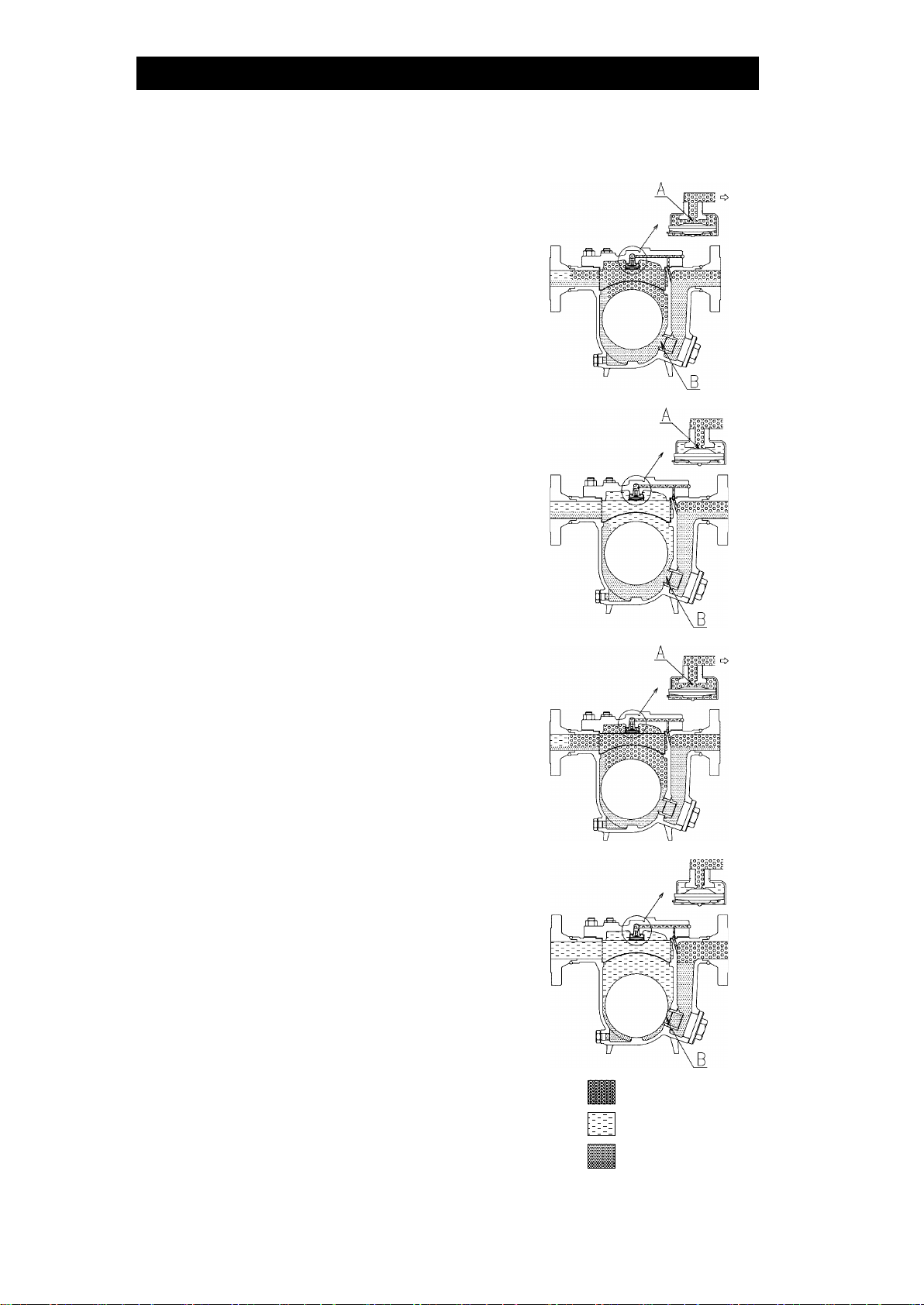
Operation
Principles of air and condensate discharge:
1. Start-up Air and Cold Condensate
Discharge
At start-up, before steam is supplied, the trap is
cold so the X-element is contracted and the air
vent valve seat (A) is open. This allows for the
rapid discharge of air through the air vent valve
(A) and cold condensate through the orifice (B),
when steam is first supplied to the system.
2. Condensate Discharge
After the discharge of initial air and cold
condensate, the heat of the inflowing steam and
condensate causes the X-element to expand,
closing the air vent valve (A). The rising
condensate level causes the float to rise due to
buoyancy, opening the orifice (B) and allowing
condensate to be discharged.
3. Hot Air Discharge
Should hot air flow into the trap with the steam
during normal operation, the temperature of the
X-element drops, causing it to momentarily
contract and open the air vent valve (A), which
allows for the rapid discharge of the air. After the
air is discharged and steam contacts the
X-element, the temperature will increase
causeing the air vent valve (A) to close
4. Closed Position
When the condensate flow rate decreases, the
X-element expands due to the heat of the steam,
closing the air vent valve (A). In addition, the float
falls as condensate is discharged, closing off the
orifice (B). A water seal is maintained at all times
over the orifice (B) to prevent steam loss.
Air
Steam
Condensate
172-65457MA-02 (JH7.2R-X) 14 Jul 2015
6
Specifications
Install properly and DO NOT use this product outside the recommended
operating pressure, temperature and other specification ranges.
Improper use may result in such hazards as damage to the product or
malfunctions which may lead to serious accidents. Local regulations
may restrict the use of this product to below the conditions quoted.
CAUTION
DO NOT use this product in excess of the maximum operating pressure
differential; such use could make discharge impossible (blocked).
CAUTION
Use only under conditions in which no freeze-up will occur. Freezing
may damage the product, leading to fluid discharge, which may cause
burns or other injury.
CAUTION
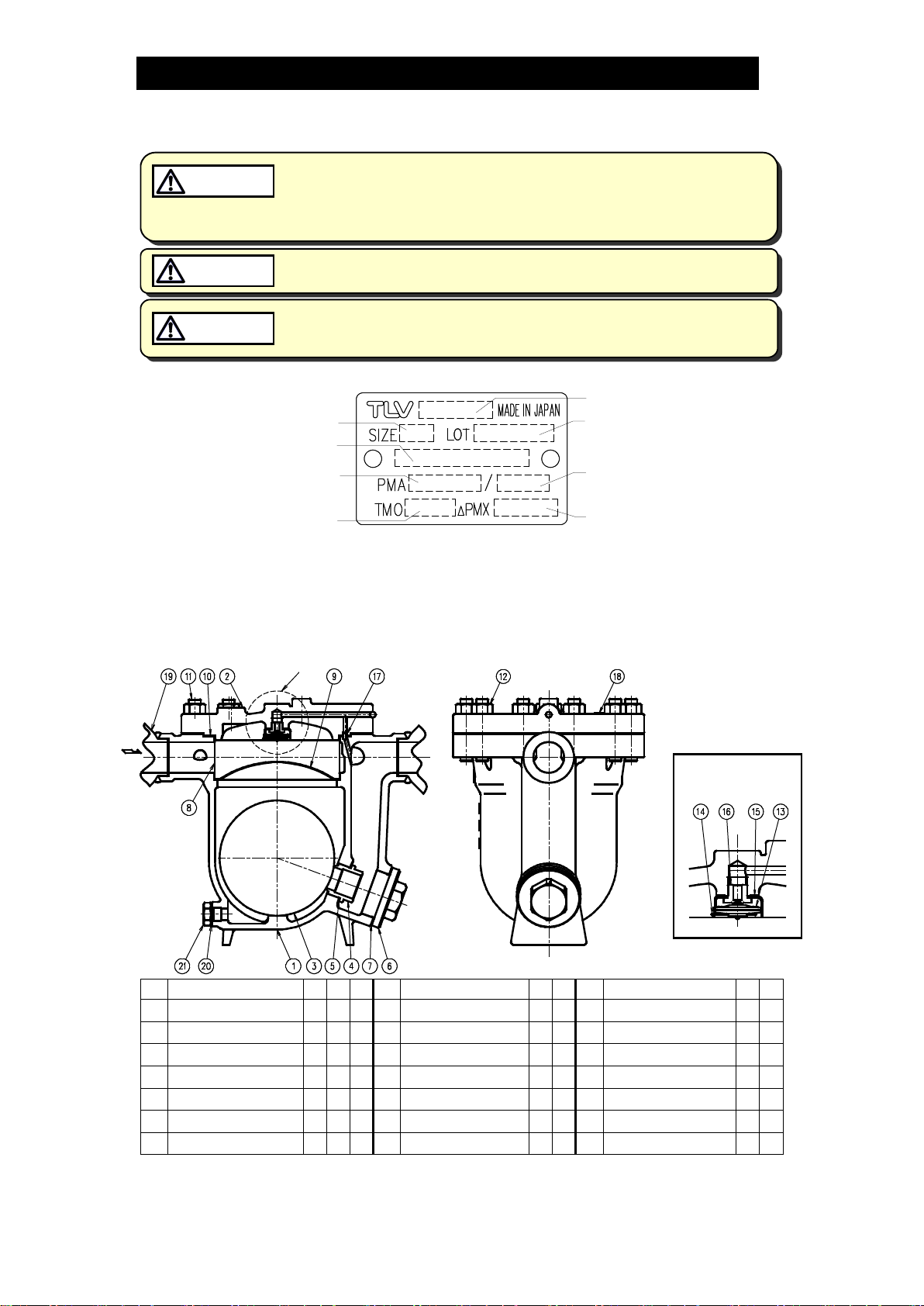
Refer to the product nameplate for detailed specifications.
Model
Maximum Allowable
Temperature (TMA)*
Maximum Allowable
Pressure*
Nominal Diameter
Maximum Differential
Pressure
Production Lot No.
Valve No.**
Maximum Operating
Temperature
* Maximum allowable pressure (PMA) and maximum allowable temperature (TMA) are PRESSURE
SHELL DESIGN CONDITIONS, NOT OPERATING CONDITIONS.
** Valve No. is displayed for products with options. This item is omitted from the nameplate when there
are no options.
Configuration
No.
Name
M*
R*
F*
No.
Name
M*
R*
No.
Name
M*
R*
1
Body
8
Screen
15
X-element Guide
2
Cover
9
Screen Holder
16
Air Vent Valve Seat
3
Float
10
Cover Gasket
17
Connector
4
Orifice
11
Cover Bolt
18
Nameplate
5
Orifice Gasket
12
Cover Nut
19
Socket / Flange
6
Orifice Plug
13
X-element
20
Drain Plug Gasket
7
Orifice Plug Gasket
14
Spring Clip
21
Drain Plug
* Replacement parts are available only in the following kits: M = Maintenance Kit, R = Repair Kit,
F= Float
A - Detail View
A
172-65457MA-02 (JH7.2R-X) 14 Jul 2015
7
Installation
Install properly and DO NOT use this product outside the recommended
operating pressure, temperature and other specification ranges.
Improper use may result in such hazards as damage to the product or
malfunctions which may lead to serious accidents. Local regulations
may restrict the use of this product to below the conditions quoted.
CAUTION
Use hoisting equipment for heavy objects (weighing approximately
20 kg (44 lb) or more). Failure to do so may result in back strain or other
injury if the object should fall.
CAUTION
Take measures to prevent people from coming into direct contact with
product outlets. Failure to do so may result in burns or other injury from
the discharge of fluids.
CAUTION
Installation, inspection, maintenance, repairs, disassembly, adjustment, and valve
opening/closing should be carried out only by trained maintenance personnel.
1. Before installation, be sure to remove all protective seals.
2. Before installing the product, open the inlet valve and blow out the piping to
remove any piping scraps, dirt and oil. Close the inlet valve after blowdown.
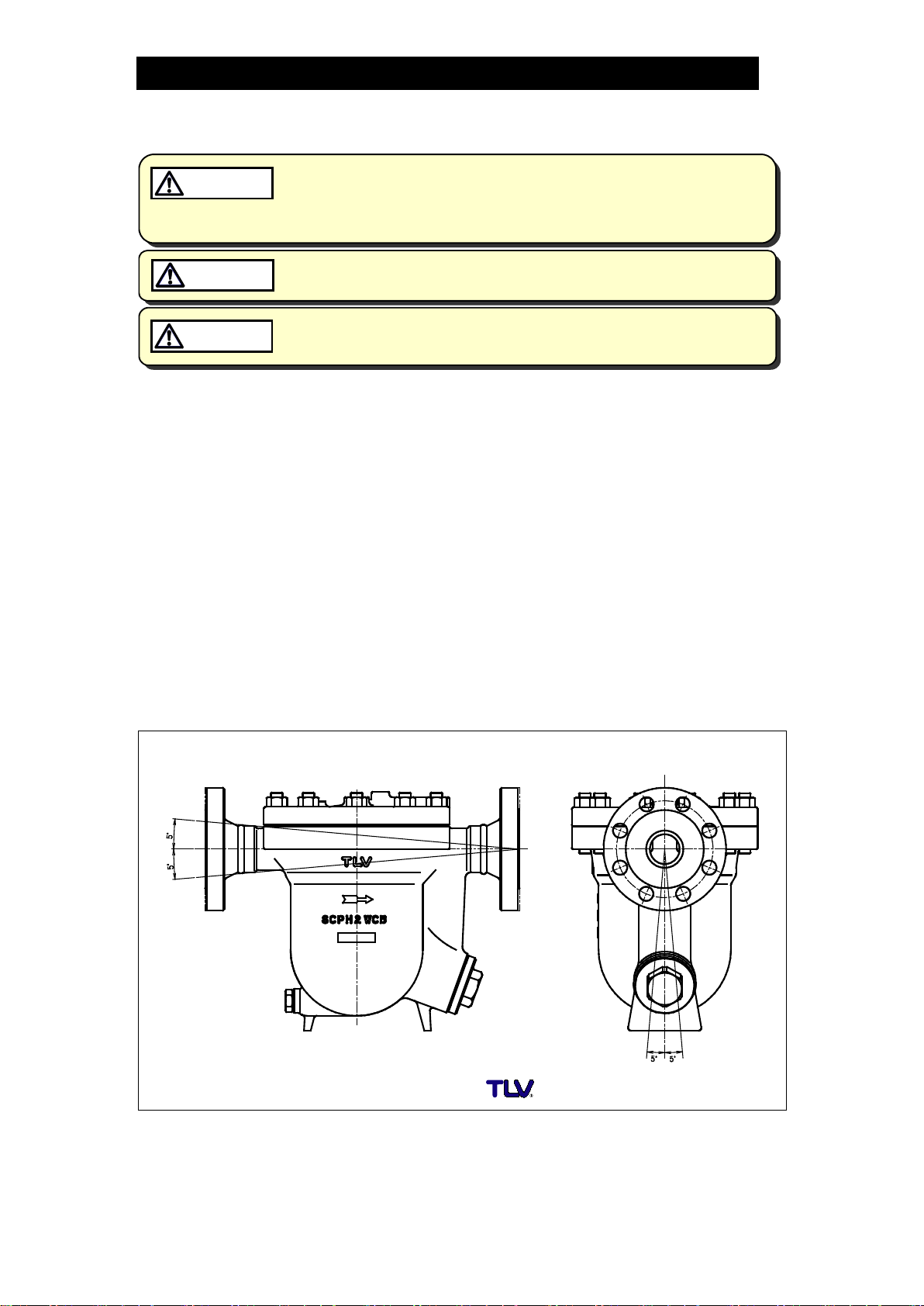
3. Install the product so the arrow on the body is pointing in the direction of flow.
4. The trap should be inclined no more than 5° horizontally and front-to-back.
5. Install a condensate outlet valve and outlet piping.
6. Open the inlet and outlet valves and check to make sure that the product functions
properly.
If there is a problem, determine the cause using the “Troubleshooting” section in this
manual.
Tolerance Angle for Installation - 5°
Make sure the trap is installed with the raised lettering on the body horizontal.

172-65457MA-02 (JH7.2R-X) 14 Jul 2015
8
Maintenance
Take measures to prevent people from coming into direct contact with
product outlets. Failure to do so may result in burns or other injury from
the discharge of fluids.
CAUTION
Be sure to use only the recommended components when repairing the
product, and NEVER attempt to modify the product in any way. Failure to
observe these precautions may result in damage to the product or burns
or other injury due to malfunction or the discharge of fluids.
CAUTION
Operational Check
A visual inspection of the following items should be done on a daily basis to
determine whether the trap is operating properly or has failed. Periodically (at least
biannually) the operation should also be checked by using diagnostic equipment,
such as a stethoscope, thermometer, TLV Pocket TrapMan or TrapMan.
If the trap should fail, it may cause damage to piping and equipment, resulting in
faulty or low quality products or losses due to steam leakage.
Normal
:
Condensate is discharged continuously, together with flash steam,
and the sound of flow can be heard. If there is very little condensate,
there is almost no sound of flow.
Blocked
(Discharge Impossible)
:
No condensate is discharged. The trap is quiet and makes no noise,
and the surface temperature of the trap is low.
Blowing
:
Live steam continually flows from the outlet and there is a
continuous metallic sound.
Steam Leakage
:
Live steam is discharged through the trap outlet together with
condensate, accompanied by a high-pitched sound.
(When conducting a visual inspection, flash steam is sometimes mistaken for steam leakage. For
this reason, the use of a steam trap diagnostic instrument [TLV: TrapMan] in conjunction with the
visual inspection is highly recommended.)
Flash Steam
Live Steam Leakage
Parts Inspection
When parts have been removed, or during periodic inspections, use the following
table to inspect the parts and replace any that are found to be defective.
Procedure
Gaskets: check for warping or scratches
Screen: check for clogging or corrosion
X-element, Air Vent Valve Seat: check for scratches
Float: check for scratches or dents
Check for build-up inside the body
Orifice Opening: check for dirt, oil film, wear or scratches
White jet
containing
water droplets
Clear, slightly
bluish jet
172-65457MA-02 (JH7.2R-X) 14 Jul 2015
9
Disassembly / Reassembly
NEVER apply direct heat to the float. The float may explode due to
increased internal pressure, causing accidents leading to serious injury
or damage to property and equipment.
WARNING
Use hoisting equipment for heavy objects (weighing approximately
20 kg (44 lb) or more). Failure to do so may result in back strain or other
injury if the object should fall.
CAUTION
When disassembling or removing the product, wait until the internal
pressure equals atmospheric pressure and the surface of the product
has cooled to room temperature. Disassembling or removing the
product when it is hot or under pressure may lead to discharge of fluids,
causing burns, other injuries or damage.
CAUTION
Use the following procedures to remove components. Use the same procedures in
reverse to reassemble. (Installation, inspection, maintenance, repairs, disassembly,
adjustment and valve opening/closing should be carried out only by trained
maintenance personnel.)
Drain Plug
Part
During Disassembly
During Reassembly
Drain Plug
Remove with a socket
wrench
Consult the table of tightening torques and tighten to the
proper torque
Drain Plug
Gasket
Remove the gasket
and clean sealing
surface
Replace with new gasket; coat surfaces with anti-seize
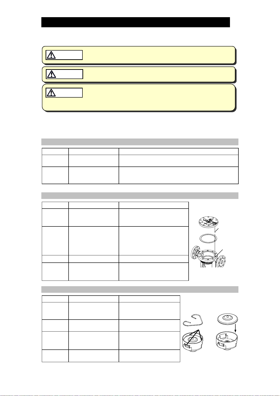
Detaching / Reattaching the Cover
Part
During Disassembly
During Reassembly
Cover Nut
Remove with a socket
wrench
Consult the table of tightening
torques and tighten to the proper
torque
Cover
Remove by lifting up
and off
Make sure there are no pieces
of the old gasket left on the
sealing surfaces of the body and
cover, align with the connector
and reattach (figure A)
Connector
Remove the connector
Insert into the hole in the body
Cover
Gasket
Remove the gasket
and clean sealing
surface
Replace with a new gasket, be
sure the hole for the connector
lines up with the hole in the body
Disassembly / Reassembly of Components Inside the Cover
Part
During Disassembly
During Reassembly
Spling Clip
Pinch the insides
together and remove
from the X-element guide
Insert securely into the grooves
in the X-element guide (figure
B)
X-element
Remove from the
X-element guide
Insert after making sure of the
correct orientation (figure C)
Air Vent
Valve Seat
Remove with a socket
wrench
Consult the table of tightening
torques and tighten to the
proper torque
X-element
Guide
Remove without bending
Insert the X-element gently
Figure A
Connector
Hole in
body
Figure B
Figure C
Grooves

172-65457MA-02 (JH7.2R-X) 14 Jul 2015
10
Disassembly / Reassembly of Components Inside the Body
Note: The X-element case must be removed before the float can be removed.
Part
During Disassembly
During Reassembly
Screen
Lift straight up and out
while turning
Place on the screen holder, making sure that the
top of the screen does not stick up out of the body
Screen Holder
Remove without bending
Place on the ledge inside the body, making sure
the rounded side is on top
Float
Remove, being careful not
to scratch the polished
surface
Insert, being careful not to scratch the polished
surface
Orifice Plug
Remove with a box
wrench
Consult the table of tightening torques and tighten
to the proper torque
Orifice Plug
Gasket
Remove the gasket and
clean sealing surface
Replace with a new gasket; coat surfaces with
anti-seize
Orifice
Remove with a box
wrench
Consult the table of tightening torques and tighten
to the proper torque
Orifice Gasket
Remove the gasket and
clean sealing surface
Replace with a new gasket; coat surfaces with
anti-seize
Table of Tightening Torques
Part Name
Torque
Distance Across Flats
N⋅m
(lbf⋅ft)
mm
(in)
Cover Nut
150
(110)
24
(15⁄16)
Air Vent Valve Seat
35
(26)
19
(¾)
Orifice Plug
700
(510)
46
(113⁄16)
Orifice
350
(260)
38
(1½)
Drain Plug
100
(73)
26
(1)
NOTE: - Coat all threaded portions with anti-seize. (1 N⋅m ≈10 kg⋅cm)
- If drawings or other special documentation were supplied for the product, any torque
given there takes precedence over values shown here.

172-65457MA-02 (JH7.2R-X) 14 Jul 2015
11
Exploded View
Drain Plug Gasket
Cover
Cover Nut
Cover Bolt
Cover Gasket
Screen holder
Drain Plug
Orifice
Body
Screen
Float
Orifice Gasket
Orifice Plug Gasket
Orifice Plug
X-element Guide
Air Vent Valve Seat
X-element
Spring Clip
Connector
172-65457MA-02 (JH7.2R-X) 14 Jul 2015
12
3
5
6
Gasket
Do not pinch gasket
in thread recesses
4
Coat with anti-seize
Gasket Surface
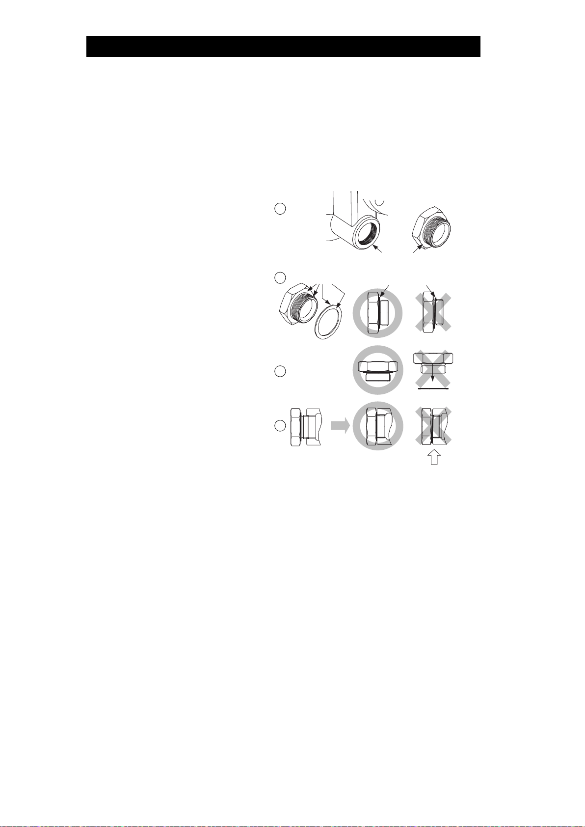
Instructions for Plug / Holder Disassembly and Reassembly
The seal on the threaded plugs/holders found on TLV products is formed by a flat
metal gasket. There are various installation orientations for the gaskets, such as
horizontal, diagonal and downward, and the gasket may be pinched in the thread
recesses during assembly.
Instructions for Disassembly and Reassembly
①Remove the plug/holder using
a tool of the specified size
(distance across flats).
②The gasket should not be
reused. Be sure to replace it
with a new gasket.
③Clean the gasket surfaces of
the plug/holder and the product
body using a rag and/or
cleaning agents, then check to
make sure the surfaces are not
scratched or deformed.
④Coat both the gasket surface
of the plug/holder and the
threads of the plug/holder with
anti-seize, then press the
gasket onto the center of the
gasket surface of the
plug/holder, making sure the
anti-seize affixes the gasket
tightly to the plug/holder.
Check to make sure the
gasket is not caught in the
recesses of the threads.
⑤Hold the plug/holder upside down to make sure that the anti-seize makes the
gasket stick to the plug/holder even when the plug/holder is held upside down.
⑥Screw the plug/holder by hand into the product body while making sure that the
gasket remains tightly affixed to the center of the gasket surface of the
plug/holder. Make sure the entire gasket is making contact with the gasket
surface of the product body. It is important at this point to make sure the gasket
is not pinched in the thread recesses of the plug/holder.
⑦Tighten the plug/holder to the proper torque.
⑧Next, begin the supply of steam and check to make sure there is no leakage
from the part just tightened. If there is leakage, immediately close the inlet valve
and, if there is a bypass valve, take the necessary steps to release any residual
pressure. After the surface of the product cools to room temperature, repeat the
procedure beginning from step 1.
172-65457MA-02 (JH7.2R-X) 14 Jul 2015
13
Troubleshooting
NEVER apply direct heat to the float. The float may explode due to
increased internal pressure, causing accidents leading to serious injury
or damage to property and equipment.
WARNING
When disassembling or removing the product, wait until the internal
pressure equals atmospheric pressure and the surface of the product
has cooled to room temperature. Disassembling or removing the
product when it is hot or under pressure may lead to discharge of fluids,
causing burns, other injuries or damage.
CAUTION
If the product fails to operate properly, use the following table to locate and remedy
the cause.
Problem
Cause
Remedy
No condensate is
discharged
(blocked) or
discharge is poor
The float is damaged or filled with
condensate
Replace with a new float
The orifice opening, screen or piping are
clogged with rust and scale
Clean parts
The X-element is scratched or damaged
Replace with a new X-element
Steam-locking has occurred
Perform a bypass blowdown or
close the trap inlet valve and
allow the trap to cool
The trap operating pressure exceeds the
maximum specified pressure, or whether
there is insufficient pressure differential
between the trap inlet and outlet
Compare specifications and
actual operating conditions
Steam is
discharged or leaks
from the outlet
(blowing)
(steam leakage)
Build-up on the seating surface of the
orifice or rust and scale build-up beneath
the float
Clean parts
Scratches on the orifice
Replace with a new orifice
The float is misshapen or has a build-up
Clean or replace with a new
float
Improper installation orientation
Correct the installation
Trap vibration
Lengthen the inlet piping and
fasten it securely
The air vent valve seating area of the
X-element and/or air vent valve seat
have a build-up or are scratched
Clean the air vent valve seating
area of the X-element and/or
air vent valve seat or replace
the X-element unit
Steam is leaking
from a place other
than the outlet
Gasket deterioration or damage
Replace with new gasket(s)
Improper tightening torques were used
Tighten to the proper torque
Float frequently
becomes damaged
Water hammer has occurred
Study and correct the piping
NOTE: When replacing parts with new, use the parts list for reference, and replace with parts from the
Maintenance Kit, Repair Kit, etc. Please note that replacement parts are only available as part of
a replacement parts kit.

172-65457MA-02 (JH7.2R-X) 14 Jul 2015
14
Product Warranty
1. Warranty Period
One year following product delivery.
2. Warranty Coverage
TLV CO., LTD. warrants this product to the original purchaser to be free
from defective materials and workmanship. Under this warranty, the
product will be repaired or replaced at our option, without charge for parts
or labor.
3. This product warranty will not apply to cosmetic defects, nor to any product
whose exterior has been damaged or defaced; nor does it apply in the
following cases:
1) Malfunctions due to improper installation, use, handling, etc., by other
than TLV CO., LTD. authorized service representatives.
2) Malfunctions due to dirt, scale, rust, etc.
3) Malfunctions due to improper disassembly and reassembly, or
inadequate inspection and maintenance by other than TLV CO., LTD.
authorized service representatives.
4) Malfunctions due to disasters or forces of nature.
5) Accidents or malfunctions due to any other cause beyond the control
of TLV CO., LTD.
4. Under no circumstances will TLV CO., LTD. be liable for consequential
economic loss damage or consequential damage to property.
* * * * * * *
For Service or Technical Assistance:
Contact your representative or your regional office.
Manufacturer
CO., LTD.
881 Nagasuna, Noguchi
Kakogawa, Hyogo 675-8511 JAPAN
Tel: 81-(0)79 - 427 - 1800

172-65457MA-02 (JH7.2R-X) 14 Jul 2015
15
Options
The options shown below are available for this product on
request. Please compare with the product you received.
Options for Area A (standard: with drain plug)
Without Drain Plug
Options for Area B (standard: no equipment)
Use gloves when operating the needle valve and keep all body parts well
clear of the product. Failure to do so could result in burns, other injury or
damage from the blowing of small amounts of steam and condensate.
CAUTION
•Operating Instructions for Needle Valve
1. When shipped from the factory, the needle valve is in the closed position.
2. To operate the needle valve, insert a flat-head screwdriver into the slot on the top
of the needle valve and:
- Open Valve: slowly turn counterclockwise. (Do not continue turning the needle
valve past the point at which the snap ring contacts the bottom of the gland case.)
•See the table below to determine the amount of steam discharge
- Close Valve: slowly turn clockwise. (Do not continue turning the needle valve
past the point at which it stops.)
3. If steam should leak from the gland retainer nut or gland case, it can be stopped
by further tightening the gland retainer nut. (Do not over tighten, otherwise the
needle valve may seize and become unworkable)
Needle Valve Unit (Model: JH7.2R-NV)
Gland Case
Torque: 30 N∙m (22 lbf∙ft)
19 mm ( ¾” ) across flats
Gland Packing
Gasket
Gland Retainer Nut
Torque: 30 N
∙m (22 lbf∙ft)
22 mm (
7⁄8” )across flats
Needle Valve
Snap Ring
172-65457MA-02 (JH7.2R-X) 14 Jul 2015
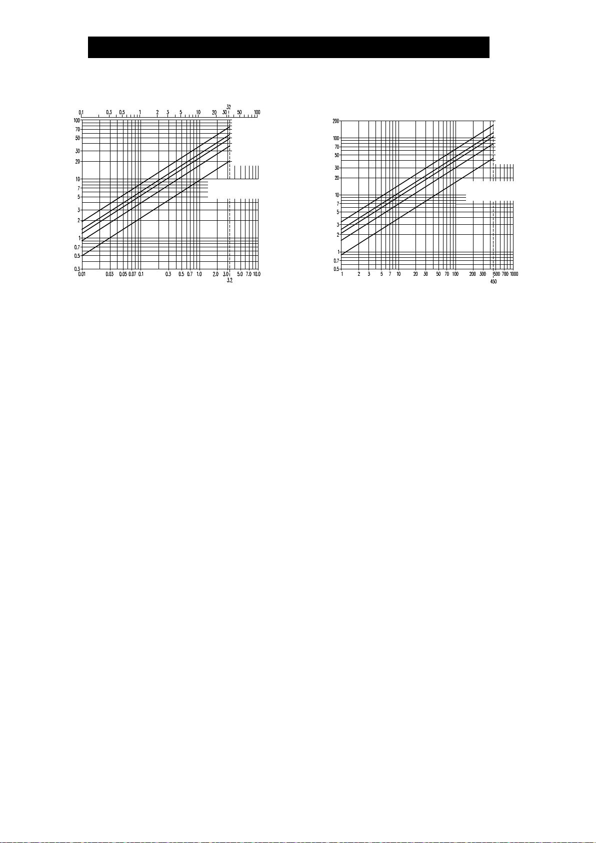
16
Steam Discharge
Differential Pressure (MPa)
Discharge Capacity (kg/h)
Differential Pressure (kg/cm
2
)
More than 1.5 turns
1 Turn
¾ Turn
½ Turn
¼ Turn
Number of turns from
full-closed position
Differential Pressure (psi)
Discharge Capacity (lb/h)
More than 1.5 turns
1 Turn
¾ Turn
½ Turn
¼ Turn
Number of turns from
full-closed position
Table of contents
Other TLV Plumbing Product manuals


Popular Plumbing Product manuals by other brands

Hans Grohe
Hans Grohe AXOR Uno 45119 Series Assembly instructions

Sanipex
Sanipex BAGNO DESIGN BDA-MLI-V002 Series installation guide

Kohler
Kohler K-3597 Homeowner's guide

Mirabelle
Mirabelle ST. MARTIN MIRSM8010CP installation instructions

KWC
KWC AQRM464FIN Installation and operating instructions

Pfister
Pfister Rosslyn F-529-7RSS Quick installation guide


Toto
Toto 0GU5020 Installation and owner's manual

Santec
Santec Caprie 9470EZ Installation instruction

Triton
Triton AS2000XT Installation and operating instructions

Consolar
Consolar TUBO II C manual

Hans Grohe
Hans Grohe Talis Classic Assembly and use instructions

Grohe
Grohe Grohtherm 3000 19 691 instructions