TLV JH8R-P User manual

172-65465MA-04 (JH8R-P) 11 May 2018
Free Float Steam Trap
JH8R-P
(Optional Models)
JH8R-W / JH8R-F / JH8R-V
Copyright © 2018 by TLV CO., LTD.
All rights reserved

172-65465MA-04 (JH8R-P) 11 May 2018
1
Contents
Introduction .......................................................................1
Safety Considerations.......................................................2
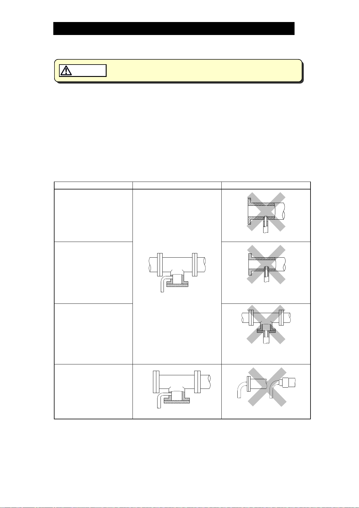
Checking the Piping..........................................................4
Operation ..........................................................................5
Specifications....................................................................6
Configuration.....................................................................6
Installation.........................................................................7
Maintenance......................................................................8
Disassembly/Reassembly.................................................9
Instructions for Plug/Holder Disassembly and Reassembly...12
Troubleshooting ..............................................................13
Product Warranty ............................................................14
Options............................................................................15
Introduction
Thank you for purchasing the Free Float Steam Trap.
This product has been thoroughly inspected before being shipped from the factory.
When the product is delivered, before doing anything else, check the specifications
and external appearance to make sure nothing is out of the ordinary. Also be sure to
read this manual carefully before use and follow the instructions to be sure of using
the product properly.
This instruction manual is edited based on the JH-P Series (with cover plug). The
JH-W Series (with socket welded cover connection), JH-F Series (with flanged cover
connection) and JH-V Series (with manual air vent valve) are described at the end of
this manual in the 'Option’ section.
This free float steam trap employs a hinge-less and lever-less free float to rapidly,
automatically and continuously discharge the inflowing condensate that is
continuously generated inside the equipment, thus preventing the accumulation of
condensate and thereby improving the heat transfer efficiency of the equipment.
This free float steam trap is suitable for process systems and steam-using
equipment under long continuous operation with the introduction of almost no air.
If detailed instructions for special order specifications or options not contained in this
manual are required, please contact for full details.
This instruction manual is intended for use with the model(s) listed on the front cover.
It is necessary not only for installation but for subsequent maintenance,
disassembly/reassembly and troubleshooting. Please keep it in a safe place for
future reference.

172-65465MA-04 (JH8R-P) 11 May 2018
2
Safety Considerations
•Read this section carefully before use and be sure to follow the instructions.
•Installation, inspection, maintenance, repairs, disassembly, adjustment and valve
opening/closing should be carried out only by trained maintenance personnel.
•The precautions listed in this manual are designed to ensure safety and prevent
equipment damage and personal injury. For situations that may occur as a result
of erroneous handling, three different types of cautionary items are used to
indicate the degree of urgency and the scale of potential damage and danger:
DANGER, WARNING and CAUTION.
•The three types of cautionary items above are very important for safety: be sure to
observe all of them as they relate to installation, use, maintenance, and repair.
Furthermore, TLV accepts no responsibility for any accidents or damage occurring
as a result of failure to observe these precautions.
Symbols
Indicates a DANGER, WARNING or CAUTION item.
DANGER
Indicates an urgent situation which poses a threat of death or
serious injury
WARNING
Indicates that there is a potential threat of death or serious injury
CAUTION
Indicates that there is a possibility of injury or equipment /
product damage
WARNING
NEVER apply direct heat to the float.
The float may explode due to increased internal pressure, causing
accidents leading to serious injury or damage to property and
equipment.
CAUTION
Install properly and DO NOT use this product outside the
recommended operating pressure, temperature and other
specification ranges.
Improper use may result in such hazards as damage to the product
or malfunctions that may lead to serious accidents. Local regulations
may restrict the use of this product to below the conditions quoted.
DO NOT use this product in excess of the maximum operating
pressure differential.
Such use could make discharge impossible (blocked).
Use hoisting equipment for heavy objects (weighing
approximately 20 kg (44 lb) or more).
Failure to do so may result in back strain or other injury if the object
should fall.
Use the eye bolts for removing the cover only; DO NOT use the
eye bolts for hoisting the product.
Eye bolts may break under strain, possibly resulting in serious injury.
Take measures to prevent people from coming into direct
contact with product outlets.
Failure to do so may result in burns or other injury from the
discharge of fluids.
Safety considerations continued on next page.

172-65465MA-04 (JH8R-P) 11 May 2018
3
CAUTION
When disassembling or removing the product, wait until the
internal pressure equals atmospheric pressure and the surface
of the product has cooled to room temperature.
Disassembling or removing the product when it is hot or under
pressure may lead to discharge of fluids, causing burns, other
injuries or damage.
Be sure to use only the recommended components when
repairing the product, and NEVER attempt to modify the
product in any way.
Failure to observe these precautions may result in damage to the
product and burns or other injury due to malfunction or the
discharge of fluids.
Use only under conditions in which no freeze-up will occur.
Freezing may damage the product, leading to fluid discharge, which
may cause burns or other injury.
Use only under conditions in which no water hammer will
occur.
The impact of water hammer may damage the product, leading to
fluid discharge, which may cause burns or other injury.

172-65465MA-04 (JH8R-P) 11 May 2018
4
Checking the Piping
Use only under conditions in which no water hammer will occur. The
impact of water hammer may damage the product, leading to fluid
discharge, which may cause burns or other injury.
CAUTION
Check to make sure that the pipes to be connected to the trap have been installed
properly.
1. Is the pipe diameter suitable?
2. Is the piping where the trap is to be installed horizontal?
3. Has sufficient space been secured for maintenance?
4. Have isolation valves been installed at the inlet and outlet? If the outlet is subject
to back pressure, has a check valve (TLV-CK) been installed?
5. Is a bypass valve installed?
6. Is the inlet pipe as short as possible, with as few bends as possible, and installed
so the liquid will flow naturally down into the trap?
7. Has the piping work been done correctly, as shown in the figures below?
Requirement
Correct
Incorrect
Install catchpot with the
proper diameter.
Diameter is too small.
Make sure the flow of
condensate is not
obstructed.
Diameter is too small and inlet
protrudes into pipe interior.
To prevent rust and scale
from flowing into the trap,
the inlet pipe should be
connected 25 – 50 mm (1 –
2 in) above the base of the
T-pipe.
Rust and scale flow into the trap
with the condensate.
When installing on the blind
end, make sure the flow of
condensate is not
obstructed.
Condensate collects in the pipe.

172-65465MA-04 (JH8R-P) 11 May 2018
5
Operation
Principles of condensate discharge:
As much air as possible should be eliminated at start-up using a bypass valve or
blowdown line.
1. Condensate Discharge
As steam is supplied, condensate flow begins.
The rising condensate level causes the float to
rise due to buoyancy, opening the orifice (A)
and allowing condensate to be discharged.
2. Discharge of Large Quantities of
Condensate
Increases in the condensate inflow rate cause
the condensate level in the trap to rise. The float
consequently rises and enlarges the opening of
the orifice (A), allowing more condensate to be
discharged. In this manner, continuous
condensate discharge occurs while the opening
size of the orifice varies depending on the
condensate flow rate.
3. Closed Position
When the condensate flow rate decreases, the
float falls, closing off the orifice (A) opening. A
water seal is maintained at all times over the
orifice (A) to prevent steam loss.
Air
Steam
Condensate

172-65465MA-04 (JH8R-P) 11 May 2018
6
Specifications
Install properly and DO NOT use this product outside the recommended
operating pressure, temperature and other specification ranges.
Improper use may result in such hazards as damage to the product or
malfunctions which may lead to serious accidents. Local regulations
may restrict the use of this product to below the conditions quoted.
CAUTION
DO NOT use this product in excess of the maximum operating pressure
differential; such use could make discharge impossible (blocked).
CAUTION
Use only under conditions in which no freeze-up will occur. Freezing
may damage the product, leading to fluid discharge, which may cause
burns or other injury.
CAUTION
Refer to the product nameplate for detailed specifications.
Model
Maximum Allowable
Temperature (TMA)*
Maximum Allowable
Pressure*
Maximum Operating
Temperature
Nominal Diameter
Maximum Differential
Pressure
Valve No.** Production Lot No.
* Maximum allowable pressure (PMA) and maximum allowable temperature (TMA) are PRESSURE
SHELL DESIGN CONDITIONS, NOT OPERATING CONDITIONS.
** Valve No. is displayed for products with options. This item is omitted from the nameplate when there
are no options.
Configuration
No.
Name
M*
R*
F*
1
Body
2
Cover
3
Float
4
Orifice
5
Orifice Gasket
6
Outlet Cover Gasket
7
Screen
8
Screen Holder
9
Snap Ring
10
Cover Gasket
11
Cover Bolt
12
Cover Nut
13
Outlet Cover
14
Outlet Cover Bolt
15
Outlet Cover Nut
16
Nameplate
17
Screen Holder Retainer
18
Eye Bolt
19
Flange / Socket
20
Drain Plug Gasket
21
Drain Plug
22
Plug Gasket
23
Plug
24
Cover Plug Gasket
25
Cover Plug
* Replacement parts are available only in the
following kits:
M = Maintenance Kit
R = Repair Kit
F = Float

172-65465MA-04 (JH8R-P) 11 May 2018
7
Installation
Install properly and DO NOT use this product outside the recommended
operating pressure, temperature and other specification ranges.
Improper use may result in such hazards as damage to the product or
malfunctions which may lead to serious accidents. Local regulations
may restrict the use of this product to below the conditions quoted.
CAUTION
Use hoisting equipment for heavy objects (weighing approximately
20 kg (44 lb) or more). Failure to do so may result in back strain or other
injury if the object should fall.
CAUTION
Use the eye bolts for removing the cover only; DO NOT use the eye bolts
for hoisting the product. Eye bolts may break under strain, possibly
resulting in serious injury.
CAUTION
Take measures to prevent people from coming into direct contact with
product outlets. Failure to do so may result in burns or other injury from
the discharge of fluids.
CAUTION
Installation, inspection, maintenance, repairs, disassembly, adjustment and valve
opening/closing should be carried out only by trained maintenance personnel.
1. Before installation, be sure to remove all protective seals.
2. Before installing the product, open the inlet valve and blow out the piping to
remove any piping scraps, dirt and oil. Close the inlet valve after blowdown.
3. Install the product so the arrow on the body is pointing in the direction of flow.
4. The product should be hoisted with wire placed at inlet/outlet flange.
5. The product should be inclined no more than 5° horizontally and front-to-back.
6. Install a condensate outlet valve and outlet piping.
7. Air in the system at start-up should be discharged using a bypass valve or
blowdown line.
8. Open the inlet and outlet valves and check to make sure that the product
functions properly.
If there is a problem, determine the cause using the “Troubleshooting” section in this
manual.
Tolerance Angle for Installation: 5°
Make sure the product is installed with the raised lettering on the body horizontal.

172-65465MA-04 (JH8R-P) 11 May 2018
8
Maintenance
Take measures to prevent people from coming into direct contact with
product outlets. Failure to do so may result in burns or other injury from
the discharge of fluids.
CAUTION
Be sure to use only the recommended components when repairing the
product, and NEVER attempt to modify the product in any way. Failure to
observe these precautions may result in damage to the product or burns
or other injury due to malfunction or the discharge of fluids.
CAUTION
Operational Check
A visual inspection of the following items should be done on a daily basis to
determine whether the trap is operating properly or has failed. Periodically (at least
biannually) the operation should also be checked by using diagnostic equipment,
such as a stethoscope or thermometer.
If the trap should fail, it may cause damage to piping and equipment, resulting in
faulty or low quality products or losses due to steam leakage.
Normal
:
Condensate is discharged continuously, together with flash steam,
and the sound of flow can be heard. If there is very little condensate,
there is almost no sound of flow.
Blocked
(Discharge Impossible)
:
No condensate is discharged. The trap is quiet and makes no noise,
and the surface temperature of the trap is low.
Blowing
:
Live steam continually flows from the outlet and there is a
continuous metallic sound.
Steam Leakage
:
Live steam is discharged through the trap outlet together with
condensate, accompanied by a high-pitched sound.
Flash Steam
Live Steam Leakage
Parts Inspection
When parts have been removed, or during periodic inspections, use the following
table to inspect the parts and replace any that are found to be defective.
Procedure
Gaskets:
Check for warping or scratches
Screen:
Check for clogging or corrosion
Float:
Check for scratches or dents
Body Interior:
Check for build-up
Orifice Opening:
Check for dirt, oil film, wear or scratches
White jet
containing
water droplets
Clear, slightly
bluish jet

172-65465MA-04 (JH8R-P) 11 May 2018
9
Disassembly/Reassembly
NEVER apply direct heat to the float. The float may explode due to
increased internal pressure, causing accidents leading to serious injury
or damage to property and equipment.
WARNING
Use hoisting equipment for heavy objects (weighing approximately
20 kg (44 lb) or more). Failure to do so may result in back strain or other
injury if the object should fall.
CAUTION
Use the eye bolts for removing the cover only; DO NOT use the eye bolts
for hoisting the product. Eye bolts may break under strain, possibly
resulting in serious injury.
CAUTION
When disassembling or removing the product, wait until the internal
pressure equals atmospheric pressure and the surface of the product
has cooled to room temperature. Disassembling or removing the
product when it is hot or under pressure may lead to discharge of fluids,
causing burns, other injuries or damage.
CAUTION
Use the following procedures to remove components. Use the same procedures in
reverse to reassemble. (Installation, inspection, maintenance, repairs, disassembly,
adjustment and valve opening/closing should be carried out only by trained
maintenance personnel.)
Drain Plug
Part
During Disassembly
During Reassembly
Drain Plug
Remove with a socket wrench
Consult the table of tightening torques
and tighten to the proper torque
Drain Plug
Gasket
Remove the gasket and clean
sealing surfaces
Replace with a new gasket; coat surfaces
with anti-seize
Detaching/Reattaching the Cover and its Components
Part
During Disassembly
During Reassembly
Cover Nut
Remove with a socket wrench
Consult the table of tightening torques
and tighten to the proper torque
Cover
Use all four (4) eye bolts to lift up
and off, making sure to evenly
distribute the weight of the cover
among them
Make sure there are no pieces of the old
gasket left on the sealing surfaces of the
body and cover, align the arrows on the
body and cover and reattach
Cover Gasket
Remove the gasket and clean
sealing surfaces
Replace with a new gasket
Cover Plug
Remove with a socket wrench
Consult the table of tightening torques
and tighten to the proper torque
Cover Plug
Gasket
Remove the gasket and clean
sealing surfaces
Replace with a new gasket; coat surfaces
with anti-seize

172-65465MA-04 (JH8R-P) 11 May 2018
10
Disassembly/Reassembly of Components Inside the Body
NOTE: The plug (inside the body) must be removed before the float can be removed.
Part
During Disassembly
During Reassembly
Plug (inside
the body)
Remove with a socket wrench
Consult the table of tightening torques
and tighten to the proper torque
Plug Gasket
Remove the gasket and clean
sealing surfaces
Replace with a new gasket; coat surfaces
with anti-seize
Snap Ring
Pinch insides together and
remove from the body
Insert securely into the groove in the
body
Screen
Remove by grasping the wire ring
and lifting straight up and out
Set the screen on the screen holder and
screen holder retainer and insert as far
as the snap ring groove
Screen Holder
Retainer
Remove without bending
Place on the screen holder without tilting
Screen Holder
Remove without bending
Place on the ledge inside the body,
making sure the rounded side is on top
Float
Remove, being careful not to
scratch the polished surfaces
Insert, being careful not to scratch the
polished surface
Outlet Cover
Nut
Remove with a socket wrench
Consult the table of tightening torques
and tighten to the proper torque
Outlet Cover
Remove, being careful not to
scratch the gasket sealing
surfaces
Make sure there are no pieces of the old
gasket left on the sealing surfaces of the
body and cover
Outlet Cover
Gasket
Remove the gasket and clean
sealing surfaces
Replace with a new gasket
Orifice
Remove with a socket wrench
Consult the table of tightening torques
and tighten to the proper torque
Orifice Gasket
Remove the gasket and clean
sealing surfaces
Replace with a new gasket; coat surfaces
with anti-seize
Table of Tightening Torques
Part Name
Torque
Distance Across Flats
N⋅m
(lbf∙ft)
mm
(in)
Orifice
1000
(730)
60
(23/8)
Cover Nut
450
(330)
36
(113/32)
Outlet Cover Nut
160
(115)
24
(15/16)
Cover Plug (JH8R-P)
100
(73)
26
(1)
Plug (inside the body)
150
(110)
27
(11/16)
Drain Plug
100
(73)
26
(1)
NOTE:
-Coat all threaded portions with anti-seize.
-If drawings or other special documentation were supplied for the
product, any torque given there takes precedence over values
shown here.
(1 N⋅m ≈10 kg⋅cm)

172-65465MA-04 (JH8R-P) 11 May 2018
11
Exploded View
Cover Plug
Cover Plug Gasket
Cover Nut
Cover
Cover Gasket
Snap Ring
Screen
Screen Holder Retainer
Screen Holder
Float
Plug
Plug Gasket
Cover Bolt
Body
Drain Plug
Drain Plug Gasket
Outlet Cover Bolt
Orifice
Outlet Cover Gasket
Outlet Cover
Outlet Cover Nut

172-65465MA-04 (JH8R-P) 11 May 2018
12
Instructions for Plug/Holder Disassembly and Reassembly
The seal on the threaded plugs/holders found on TLV products is formed by a flat
metal gasket. There are various installation orientations for the gaskets, such as
horizontal, diagonal and downward, and the gasket may be pinched in the thread
recesses during assembly.
Instructions for Disassembly and Reassembly
1. Remove the plug/holder using a tool of the specified size (distance across flats).
2. The gasket should not be reused. Be sure to replace it with a new gasket.
3. Clean the gasket surfaces of the
plug/holder and the product body using
a rag and/or cleaning agents, then
check to make sure the surfaces are not
scratched or deformed.
4. Coat both the gasket surface of the
plug/holder and the threads of the
plug/holder with anti-seize, then press
the gasket onto the center of the
gasket surface of the plug/holder,
making sure the anti-seize affixes the
gasket tightly to the plug/holder.
Check to make sure the gasket is not
caught in the recesses of the threads.
5. Hold the plug/holder upside down to
make sure that the anti-seize makes
the gasket stick to the plug/holder
even when the plug/holder is held
upside down.
6. Screw the plug/holder by hand into the
product body while making sure that
the gasket remains tightly affixed to
the center of the gasket surface of the
plug/holder. Make sure the entire
gasket is making contact with the
gasket surface of the product body. It is important at this point to make sure the
gasket is not pinched in the thread recesses of the plug/holder.
7. Tighten the plug/holder to the proper torque.
8. Next, begin the supply of steam and check to make sure there is no leakage
from the part just tightened. If there is leakage, immediately close the inlet
valve and, if there is a bypass valve, take the necessary steps to release any
residual pressure. After the surface of the product cools to room temperature,
repeat the procedure beginning from step 1.
Gasket
Do not pinch gasket in
threaded recesses
Coat with
anti-seize Gasket Surface
3)
4)
5)
6)

172-65465MA-04 (JH8R-P) 11 May 2018
13
Troubleshooting
NEVER apply direct heat to the float. The float may explode due to
increased internal pressure, causing accidents leading to serious injury
or damage to property and equipment.
WARNING
When disassembling or removing the product, wait until the internal
pressure equals atmospheric pressure and the surface of the product
has cooled to room temperature. Disassembling or removing the
product when it is hot or under pressure may lead to discharge of fluids,
causing burns, other injuries or damage.
CAUTION
When the product fails to operate properly, use the following table to locate the
cause and remedy.
Problem
Cause
Remedy
No condensate is
discharged
(blocked) or
discharge is poor
The float is damaged or filled with
condensate
Replace with a new float
The orifice opening, screen or piping are
clogged with rust and scale
Clean parts
The trap operating pressure exceeds the
maximum specified pressure, or there is
insufficient pressure differential between
the trap inlet and outlet
Compare specifications and
actual operating conditions
Steam-locking has occurred
Perform a bypass blowdown
or close the trap inlet valve
and allow the trap to cool
Air binding has occurred
Perform a bypass blowdown
or consider switching to a
product with a built-in air vent
or air vent valve
Steam is
discharged or leaks
from the outlet
(blowing)
(steam leakage)
Clogged orifice opening or rust and scale
build-up beneath the float
Clean parts
Scratches on the orifice
Replace with a new orifice
The float is misshapen or has a build-up
Clean or replace with a new
float
Improper installation orientation
Correct the installation
Trap vibration
Lengthen the inlet piping and
fasten it securely
Steam is leaking
from a place other
than the outlet
Check for gasket deterioration or damage
Replace with new gasket(s)
Check to make sure that the proper
tightening torques were used
Tighten to the proper torque
Float frequently
becomes damaged
Check to see if water hammer has
occurred
Study and correct the piping
NOTE: When replacing parts with new, use the parts list for reference, and replace with parts
from the Maintenance Kit, Repair Kit, etc. Please note that replacement parts are only
available as part of a replacement parts kit.

172-65465MA-04 (JH8R-P) 11 May 2018
14
Product Warranty
1. Warranty Period
One year following product delivery.
2. Warranty Coverage
TLV CO., LTD. warrants this product to the original purchaser to be free
from defective materials and workmanship. Under this warranty, the
product will be repaired or replaced at our option, without charge for parts
or labor.
3. This product warranty will not apply to cosmetic defects, nor to any
product whose exterior has been damaged or defaced; nor does it apply in
the following cases:
1) Malfunctions due to improper installation, use, handling, etc., by other
than TLV CO., LTD. authorized service representatives.
2) Malfunctions due to dirt, scale, rust, etc.
3) Malfunctions due to improper disassembly and reassembly, or
inadequate inspection and maintenance by other than TLV CO., LTD.
authorized service representatives.
4) Malfunctions due to disasters or forces of nature.
5) Accidents or malfunctions due to any other cause beyond the control
of TLV CO., LTD.
4. Under no circumstances will TLV CO., LTD. be liable for consequential
economic loss damage or consequential damage to property.
* * * * * * *
For Service or Technical Assistance:
Contact your representative or your regional office.
Manufacturer
881 Nagasuna, Noguchi
Kakogawa, Hyogo 675-8511, JAPAN
Tel: 81-(0)79 - 427 - 1800

172-65465MA-04 (JH8R-P) 11 May 2018
15
Options
The options shown below are available for this product on
request. Please compare with the product you received.
Options for Area A (standard: with drain plug)
Without Drain Plug
Options for Area B (standard: with cover plug)
A pressure-balancing line connector can be attached to the place where the
standard product has the cover plug.
Socket Type
(Model:JH8R-W)
Flange Type
(Model: JH8R-F)
•In principle, steam traps automatically discharge inflowing condensate. However, if
low-temperature condensate in the piping blocks the trap inlet passage,
displacement inside the piping of steam by condensate is obstructed and
condensate can no longer flow into the trap (steam-locking). Traps only function in
the presence of condensate inflow. A pressure-balancing line prevents the
occurrence of steam-locking.
Install the pressure-balancing line in the following manner:
Example: Heat Exchanger
Attach the pressure-balancing line
to the trap and to either the
equipment or to an area with a
steam space.
Pressure-balancing Line
Steam

172-65465MA-04 (JH8R-P) 11 May 2018
16
Options for Area B
With Air Vent Valve
(Model: JH8R-V)
Operating the Air Vent Valve
Be sure to use only the recommended components when repairing the
product, and NEVER attempt to modify the product in any way. Failure to
observe these precautions may result in damage to the product or burns
or other injury due to malfunction or the discharge of fluids.
CAUTION
Installation, inspection, maintenance, repairs, disassembly, adjustment and valve
opening/closing should be carried out only by trained maintenance personnel.
1. Locate the air vent valve exhaust port before operating the air vent valve, and
take care to avoid being burned by hot air or steam blowing from the vent. The
exhaust port is a 2 mm (1/16″) diameter hole on the side of the air vent valve body.
DO NOT under any circumstances allow any unprotected part of your body to
come in front of this hole.
2. Never leave an open air vent valve unattended.
Tools required: 1) open-end wrench (distance across flats 17 mm (21/32″))
2) long-handled mirror to check for steam leakage after
closing the exhaust port (leaking steam cloud the mirror)
•Using the open-end wrench, slowly turn the hexagonal head of the valve stem
counterclockwise.
•Watch the exhaust port to determine the condition of the fluid discharged.
General guidelines:
Cloudy-water droplets and mist spraying out, indicating that air and
condensate are being discharged
Clear---indicating that steam is being discharged; the valve port may now
be closed
CAUTION
The air vent valve stem cannot be
removed from the air vent valve body.
Attempting to remove the valve stem by
pulling it upward may damage it and
cause burns or other injury due to
malfunction or the discharge of steam or
condensate.
Air Vent Valve Stem
Air Vent Valve Body
Exhaust Port
Cover
17 mm
(
21
/
32
in)

172-65465MA-04 (JH8R-P) 11 May 2018
17
3. Use the following procedure to close the valve and check for leaks:
•Using the open-end wrench, close by slowly turning the hexagonal head of the
valve stem clockwise until contact with the valve seat is felt.
•Apply a little more pressure to tighten securely.
NOTE: Using an ordinary open-end wrench (handle length about 160 mm
(6¼″)), the valve will close with only a light turn pressure. Tightening
with too much force may result in seizure or damage to the seat.
•After tightening, place the mirror close to the front of the exhaust port. If the
mirror clouds, the valve is not fully closed; tighten a bit more.
4. When air enters the piping at start-up, it may accumulate inside the trap and
hinder the flow of condensate (air binding). Air binding may also occur during
the normal course of trap operation, due to the slow accumulation of air inside
the trap. The air vent valve on the top of this trap is to be operated only when
air binding has occurred. Follow the instructions in the earlier part of this section
to operate the air vent valve and release the air accumulated inside the trap.
(The air vent valve is to be open only for as long as is necessary to release the
accumulated air. If left open, it is extremely dangerous, so be sure to close
tightly after operation.)
Disassembly/Reassembly of Air Vent Valve
Air Vent Valve
Unit
Remove with a wrench
Consult the table of tightening torques
and tighten to the proper torque
Air Vent Valve
Gasket
Remove the gasket and clean
sealing surfaces
Replace with a new gasket; coat surfaces
with anti-seize
Table of Tightening Torques
Part Name
Torque
Distance Across Flats
N⋅m
(lbf∙ft)
mm
(in)
Air Vent Valve Body
100
(73)
24
(15/16)
NOTE:
-Coat all threaded portions with anti-seize.
-If drawings or other special documentation were supplied for the
product, any torque given there takes precedence over values
shown here.
(1 N⋅m ≈10 kg⋅cm)
This manual suits for next models
3
Table of contents
Other TLV Plumbing Product manuals