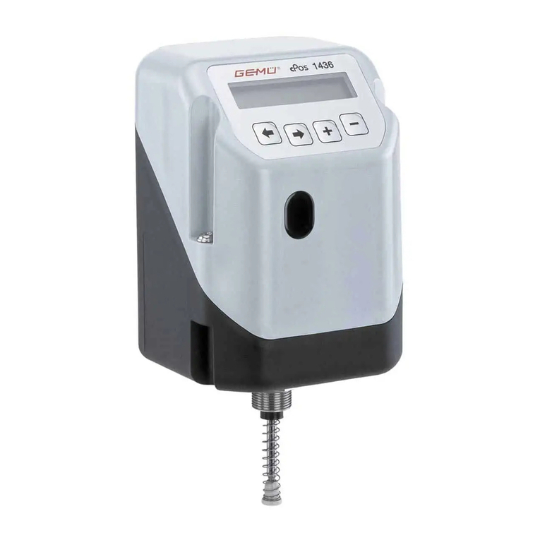
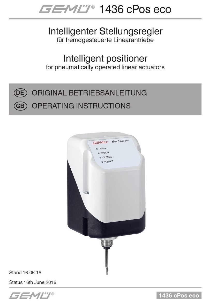
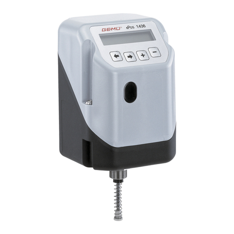
Gemu 1436 cPos eco User manual

1436 cPos
1436 cPos
Intelligent Positioner
and integrated Process Controller
Status 05.2019
From version 2.0.3.6
OPERATING INSTRUCTIONS
GB

2 / 66
1436 cPos
Quick commissioning of the GEMÜ 1436 cPos:
Prerequisites:
●Mounted to the valve.
●Air supply, max. 7bar, connected.
●24 V DC supply voltage connected.
●Set value and actual value signals need not be connected.
● For correct commissioning proceed as described in the following ow chart:
Automatic fast initialisation
The initialisation can alternatively be started via the
parameter "Init Valve".
This message is
displayed for five
seconds and then
deleted automati-
cally.
It can be switched
off within the five
seconds by pres-
sing the +key.
StartInitValve
3 Sekunden drücken
OK ESC
Init Valve ESC
OK
The GEMÜ 1436 cPos positioner
is ready for operation and reacts
to the externally specified set
value.
It must be activated separately
for the "process controller" opti-
on (see chapter 15.2).
Valve can be
opened and
closed
Switching message after
connecting the supply
voltage.
without factory setting
= Automatic
initialisation
Press 3 seconds

3 / 66 1436 cPos
Contents
1 General safety information 4
1.1 General information 4
1.2 Explanation of symbols and signs 4
1.3 Safety notes 4
1.4 Correct use 5
1.5 Information on use in damp conditions 5
1.6 Mounting position 5
1.7 Tools required for installation and assembly 5
2 Manufacturer's information 5
2.1 Transport 5
2.2 Delivery and performance 5
2.3 Storage 5
2.4 Function 5
2.5 Fail safe function 5
3 Diagrammatic view of the inputs and outputs 6
4 Mechanical mounting 7
4.1 Mounting to linear actuators 7
4.1.1 Preparation of the valve actuator 7
4.1.2 Assembling the travel sensor 7
4.1.3 Mounting the positioner 7
4.1.4 Mounting the external travel sensor
(only for version with remote mounting) 7
4.2 Mounting to quarter turn actuators 8
4.2.1 Preparation of the valve actuator 8
4.2.2 Assembling the travel sensor 8
4.2.3 Mounting the positioner 9
4.2.4 Mounting the external travel sensor
(only for version with remote mounting) 9
4.2.5 Checking the mounted assembly 9
4.3 Remote mounting to linear or quarter turn actuators 10
4.3.1 Preparation of the valve actuator 10
4.3.2 Assembling the travel sensor 10
4.3.3 Mounting the external travel sensor
(only for version with remote mounting) 10
4.3.4 Checking the mounted assembly 10
4.3.5 Mounting the mounting bracket 10
4.3.6 Connecting the travel sensor 10
5 Pneumatic connections 10
6 Electrical connections 10
6.1 Version with external actual value potentiometer
(code S01) 11
6.2 Supply voltage 11
6.3 Set value input
(only eective for AUTO operating mode) 11
6.4 Actual value input
(sensor signal when operating as a process controller) 11
6.5 Actual value output 11
6.6 Outputs 11
6.7 Digital inputs 11
6.7.1 Use of actual value and set value inputs as digital
inputs 12
6.8 Digital inputs (optional) 12
6.9 RS232 – Interface 12
7 Operation 13
7.1 Operating and display elements 13
7.2 Menu levels 13
7.2.1 Working level (Mode) 13
7.2.2 Conguration level (Setup) 13
8 Changing parameters 13
9 Commissioning 14
9.1 General information 14
9.2 Initial commissioning without factory setting
(when supplied without a valve) 14
9.2.1 Automatic initialisation 14
9.2.2 Manual initialisation 14
9.2.3 Menu structure automatic and manual initialisation 15
9.2.4 Error messages during initialisation 16
9.2.5 Initialisation parameters 17
9.3 Initial commissioning with factory setting
(positioner supplied mounted to the valve) 17
10 Operating modes 19
10.1 Operating mode selection 19
10.2 Automatic operation (A:) 19
10.3 Manual operation (M:) 19
10.4 Manual operation with exible
set value specication (F:) 19
10.5 Test mode (T:) 19
10.6 Pause mode (OFF) 19
11 Congurationmenu(Setup) 20
11.1 Changes in the conguration menu 20
11.2 Access authorisation in the conguration menu 20
11.3 Menu structure 1 Service 21
11.4 Menu structure 2 SetBasics 22
11.5 Menu structure 3 SetFunction 23
11.6 Menu structure 4 SetCalibration 24
11.7 Menu structure 5 Communication 25
12 Parameter table 26
13 Explanation of parameters 30
13.1 1 Service 30
13.1.1 Scanning the input and output signals 30
13.1.2 Activating or deactivating the user access 31
13.1.3 Reading out, deleting and deactivating error
messages 32
13.1.4 Display serial number, software version and ID and
enter TAG no. 32
13.2 2 SetBasics 33
13.2.1 Denition of actual value and set value inputs 33
13.2.2 Reset 33
13.2.3 Initialisation 33
13.2.4 Making the display settings 33
13.3 3 SetFunction 34
13.3.1 Setting the process controller parameters (optional) 34
13.3.2 Setting the positioner parameters 35
13.3.3 Setting the dead zone 35
13.3.4 Setting the optional digital input parameters 35
13.3.5 Setting output functions and switch points 36
13.3.6 Setting the error time and error action 37
13.3.7 Storing parameter sets 37
13.3.8 Dening the actual value output 37
13.4 4 SetCalibration 38
13.4.1 Determining the direction of actual value and set
value 38
13.4.2 Dening the characteristics of the control curve 38
13.4.3 Dening the direction of the travel sensor 39
13.4.4 Dening the actual value output signal 39
13.4.5 Determining switch points for error monitoring 39
13.4.6 Scaling the actual value and set value display 39
13.5 5 Communication 40
13.5.1 Setting the eldbus parameters 40
13.5.2 Setting the communication parameters 40
14 Error messages 41
15 Quick guide 42
15.1 Changing the set value signal and actual value
signal 42
15.2 Switching the process controller on or o (optional) 42
15.3 Changing the control parameters
(Proc P, Proc I, Proc D and Proc T) 43
16 General information regarding control
engineering 44
16.1 The control circuit 44
16.2 Control engineering terminology 44
16.3 Control parameters 44
16.4 Adaptation of the controller to the controlled system 45
16.5 Dierential equation for the GEMÜ 1436 cPos 45
16.6 Eects of the control parameters on the control
system 45
16.7 Control characteristics and transitory responses 46
17 Table for changes to the factory settings 47
17.1 Changed control parameters 47
17.2 Set values for the freely programmable
characteristic curve 49
18 Disposal 49
19 Returns 49
20 Information 49
21 Technical data 50
22 Order data 51
23 Fail safe function 61
24 Application examples 62
24.1 GEMÜ 1436 cPos as process controller with
4-wire transmitter (GEMÜ 3021) 62
24.2 GEMÜ 1436 cPos s process controller with
2-wire transmitter (GEMÜ 3020) 62
25 EU Declaration of Conformity 63
List of terms 64

4 / 66
1436 cPos
1 General safety information
Please read the following notes carefully and observe them.
1.1 General information
Important requirements to ensure the perfect function of this
GEMÜ 1436 cPos:
●Correct transport and storage
●Installation and commissioning by trained personnel
● Operation according to these operating instructions
●Recommended maintenance
The GEMÜ 1436 cPos must be used in accordance with
these directions. All information in these operating
instructions regarding operation, servicing and
maintenance must be observed and applied. If the
information is not observed, the operator's guarantee
rights and the manufacturer's legal liability cease.
The manufacturer shall undertake no responsibility
for the GEMÜ 1436 cPos if these safety notes are not
observed.
Therefore, you must observe:
●the contents of these operating instructions
●the relevant safety regulations for the installation and
operation of electrical systems
●that this device must not be used in potentially explosive
areas.
The regulations, standards and guidelines named in these
operating instructions are only applicable in Germany. If
the GEMÜ 1436 cPos is used in other countries, the local
applicable regulations must be observed.When dealing with
harmonised European norms, standards and guidelines, these
apply within the Single European Market.The operator must
also adhere to national rules and guidelines, if applicable.
The descriptions and instructions in these operating
instructions refer to the standard version.
All rights including copyright and industrial property
rights are expressly reserved.
The safety information does not take into account:
wUnexpected incidents and events, which may occur during
installation, operation and servicing.
wLocal safety regulations which must be adhered to by the
operator and by any additional installation personnel.
In cases of uncertainty:
wConsult the nearest GEMÜ sales oce.
1.2 Explanation of symbols and signs
Important information is identied in these operating
instructions by the following symbols:
DANGER
This symbol indicates danger.There is danger to
life or health of personsand/or considerable
material damage can occur, if the instructions
given here are not followed.
Slightbodilyinjury and damage to property
can occur, if the safety information given in
connection with this symbol is not observed.
This symbol indicates notices which
give important information regarding your
GEMÜ 1436 cPos.
1.3 Safetynotes
DANGER
● Only qualied and trained personnel should
assemble, electrically connect and commission
the GEMÜ 1436 cPos.
Use qualied personnel for operation,
servicing, inspection and assembly. The areas
of responsibility, the monitoring of personnel
and their competence areas should be dened
precisely by the operator. Train personnel with
insucient knowledge or, if necessary, have
them trained by the manufacturer / supplier on
order of the operator. Ensure that all members of
personnel understand the safety instructions.
●Ensure that the power supply equipment is
electrically safe.
●Ensure that the electrical values are correct.
DANGER
Exhaust air and cycle duties generate noise!
PHearing damage.
●Wear hearing protection.
If the safety information is disregarded then persons, the
environment and the GEMÜ 1436 cPos may be endangered.
Furthermore, failure to observe the safety information may lead
to a complete loss of claims rights.
Adhere to legal regulations.

5 / 66 1436 cPos
1.4 Correct use
wThe GEMÜ 1436 cPos is suitable for use as defined in the
data sheet. In order to ensure correct product function, the
following notes should be observed. Pay attention to the
information on the product labels.
wNon-observance of these notes and the notes in the general
operating instructions will lead to a loss of the guarantee on
the GEMÜ 1436 cPos and of legal liability.
wThe GEMÜ 1436 cPos serves solely as a positioner and
process controller and must be used according to the data
sheet.
wAny other use or use above and beyond this is not
permitted. GEMÜ shall not be liable for any consequential
damage which is solely at the user's risk.
wPlease pay attention to the pertinent technical safety
regulations when planning both the use and operation of
the device.The designer, plant constructor or operator is
always responsible for positioning and mounting of the
GEMÜ 1436 cPos.
1.5 Information on use in damp conditions
Under no circumstances whatsoever may the
GEMÜ 1436 cPos be cleaned with a high pressure
cleaning device because the protection class IP 65
is not sucient for this.
The following information is intended to help when mounting
and operating the GEMÜ 1436 cPos in damp conditions:
●Lay cables and and pipework so that condensate or rain
water that remains on the pipework / cables cannot enter
the cable glands of the M12 plugs of the GEMÜ 1436 cPos.
● Check that all cable glands of the M12 plug and the ttings
are mechanically secured.
1.6 Mounting position
The mounting position of the GEMÜ 1436 cPos is optional.
When mounted upside down it must be ensured that no liquids
or dirt can enter the outlet of the pressure relief valve.
1.7 Tools required for installation and assembly
The tools required for installation and assembly are not
included in the scope of delivery.
2 Manufacturer's information
2.1 Transport
¬Only transport the positioner by suitable means. Do not
drop. Handle carefully.
¬Dispose of packing material according to relevant local or
national disposal regulations / environmental protection
laws.
2.2 Delivery and performance
¬Check that all parts are present and check for any damage
immediately upon receipt.
¬The scope of delivery is apparent from the dispatch
documents and the design from the order number.
¬The performance of the positioner is checked at the factory.
●If the GEMÜ 1436 cPos positioner is ordered as a complete
unit with a valve, these parts and the accessories belonging
to them are supplied ready assembled and factory set. The
GEMÜ positioner is then ready for immediate operation.
2.3 Storage
¬Store the positioner free from dust and moisture in its
original packaging.
¬Avoid UV rays and direct sunlight.
¬Maximum storage temperature: 60 °C.
2.4 Function
The GEMÜ 1436 cPos is an intelligent electro-pneumatic
positioner designed for mounting to pneumatic actuators. It can
be operated as a positioner or a process controller depending
on the design.
Normally the GEMÜ 1436 cPos is mounted directly to the
actuator. The travel sensor is already integrated in the
positioner (GEMÜ 1436 cPos can be optionally ordered with an
M12 connector for remote mounting of the travel sensor).
The travel sensor measures the current position of the valve
and relays this position to the electronic control system of the
GEMÜ 1436 cPos which correlates the actual value of the
valve with the set value and adjusts the valve if necessary.
If the positioner is ordered with an additional process controller
(optional), a current actual value signal (e.g. level, pressure,
temperature, ow) is evaluated and the positioner adopts the
function of a process controller.
The information required can be called-up on the two-line
display of the GEMÜ 1436 cPos. Self-explanatory help texts
that explain the meaning of the parameters called-up are also
displayed.
The GEMÜ 1436 cPos is operated using four keys.
2.5 Fail safe function
The GEMÜ 1436 cPos has a fail safe function which ensures
that the outlets are vented during a pneumatic and electrical
power supply failure.
This fail safe function is not a substitute for specic plant safety
requirements.The GEMÜ 1436 cPos is not a safety control
system.

6 / 66
1436 cPos
3 Diagrammatic view of the inputs and outputs
Additional functions of the
positioner:
ܟAutomatic initialisation
ܟEasy to understand help texts
ܟLimitation of opening and
closing stroke
ܟClose tight function
ܟSelectable or settable
characteristic curve
ܟSafety position "fail safe"
ܟFreely programmable alarm
outputs
ܟamong other things
PID process controller function:
ܟFreely adjustable parameters
ܟSet value setting via keypad or
set value input
Operating parameters
Set value input for process or
position control
0-20 mA
4-20 mA
Actual value input for process
control
0-20 mA
4-20 mA
Actual value input for position
control using the travel sensor
Digital inputs (optional)
(Function programmable)
Supply voltage
24 V DC
InputsSupply
Actual value output
4-20 mA
e.sy-com
Communication interface
Binary outputs
24 V DC
Probus DP / DeviceNet / Pronet
OutputsInterfaces
Operation
Keypad

7 / 66 1436 cPos
4 Mechanical mounting
4.1 Mounting to linear actuators
4.1.1 Preparation of the valve actuator
1. The actuator must be in the zero position (actuator vented).
2. Should there be an optical position indicator in the actuator
(a red spindle), it must be removed.
4.1.2 Assembling the travel sensor
DANGER
Pretensioned spring!
PDamage to the device.
●Slowly relax spring.
Attention: Damage to the spindle surface may lead
to failure of the travel sensor!
The travel sensor is assembled using a mounting kit
1436S01Z... (direct mounting) or 4232S01Z... (remote
mounting) consisting of a spring, an operating bush and a
threaded adapter (if applicable).
The mounting kit depends on the valve type.
Travel sensor
Spindle Spring
Operating bush
Mounting kit
1. Pull out the spindle of the travel sensor up to the limit stop.
2. Push the spring over the spindle.
3. Fix the spindle at point a
(thespindlemustnotbedamagedduringthis
process).
a
4. Screw the operating bush onto the spindle.
4.1.3 Mounting the positioner
1
2
3
●Mount the positioner 1by screwing the travel sensor
hexagonal nut SW27 2into the actuator 3.
The positioner must not be xed by turning
the housing as this may result in the danger of
overturning the internal stop.
If correctly mounted to the valve, the positioner can be turned
370°.
4.1.4 Mounting the external travel sensor
(onlyforversionwithremotemounting)
5
3
1
Valve with external travel sensor
1. Fit positioner 1somewhere suitable.
The GEMÜ 1446 00 ZMP mounting bracket (to
be ordered separately) can be used to accom-
plish this.
2. Assemble the travel sensor (see chapter 4.1.2 "Assembling
the travel sensor").
3. Place travel sensor 5on actuator 3and attach travel
sensor 5using a suitable open-end wrench SW27.
SW27
3
5
Travel sensor and actuator
Travel sensor mounted on actuator

8 / 66
1436 cPos
4.2 Mounting to quarter turn actuators
4.2.1 Preparation of the valve actuator
10
0° / CLOSED
90° / OPEN
1. The actuator must be in the zero position (actuator ven-
ted). Double acting actuators should be moved to the valve
"CLOSED" position.
2. Remove the screw 10 which retains the optical position
indicator.
3. Determine the turn direction of the actuator (seen from
above the turn direction of the actuator must be antic-
lockwise, when the actuator moves from the "CLOSED"
to the "OPEN" position. In cases where the actuator turns
in a clockwise direction, the travel sensor's end position,
contrary to given instructions, needs to be in the opposite
direction).
4.2.2 Assembling the travel sensor
1. Before mounting the travel sensor on the actuator, make
sure that the shaft height and the hole pattern in the actua-
tor match the dimensions of the mounting bracket 6.
2. The travel sensor shaft is marked by a 2.
Set marking 2so that it is in correct alignment
with the 0° marking on the underside of travel
sensor housing 8.
In the design with an external travel sensor 9,
the 0° marking can be found on the left side of
the cable exit (the electrical turn range can be
found 90° clockwise from that position).
Information on the positioner:
The slotted holes should be positioned in the
centre on the screws. In the case of incorrect
travel set up, (determined by checking the
attachment, see chapter 4.2.5), the retainer
needs to be changed slightly while adapting
settings.
2
Travel sensor with marking
8
9
View X, only travel sensor
on positioner
View X, only travel sensor used
in the design with an external
travel sensor
0
90
View X
3. Place adapter 4onto the shaft of travel sensor 2without
turning the shaft as you do so.
2
eco
OPEN
ERROR
CLOSED
POWER
4
4. Screw positioner 1or travel sensor 4onto mounting
bracket 6
4
6
1
View X
4
6
7
90°
45°0°
6
View X with mounting bracket and adapter

9 / 66 1436 cPos
4.2.3 Mounting the positioner
1
2
4
3
6
Valve with positioner
1. Place positioner 1with adapter 4and mounting bracket 6
on actuator 3.
The adapter lug 4must engage in the actuator
shaft groove.
4
6
3
1
2. Attach mounting bracket 6to actuator 3using the screws,
washers and spring washers provided.
4
6
3
1
4.2.4 Mounting the external travel sensor
(onlyforversionwithremotemounting)
7
4
6
3
Valve with external travel sensor
In the design with an external travel sensor, the
travel sensor's cable exit protective coating is
not UV-resistant and must therefore be protected
against direct exposure to weather.
1. Fit positioner 1somewhere suitable.
The GEMÜ 1446 00 ZMP mounting bracket (to
be ordered separately) can be used to accom-
plish this.
2. Assemble the travel sensor (see chapter 4.2.2 "Assembling
the travel sensor").
3. Place travel sensor 7with adapter 4and mounting bracket
6on actuator 3.
The adapter lug 4must engage in the actuator
shaft groove.
6
7
3
4
4. Attach mounting bracket 6to actuator 3using the screws,
washers and spring washers provided.
6
3
7
Information on the travel sensor:
The slotted holes should be positioned in the
centre on the screws. In the case of incorrect
travel set up, (determined by checking the
attachment, see chapter 4.2.5), loosen the two
screws slightly and twist the travel sensor. Set
the travel up correctly and tighten the screws
again.
4.2.5 Checking the mounted assembly
1. Connect the positioner to power and air supply
(see chapter 5)
2. The following message is displayed:
NoInit
XX.X%
The mounted actuator can be moved to the OPEN and
CLOSED positions using the +and ـkeys.
The displayed valve position must be between 1 % and 99 %.
Should the display show that this range is being exceeded,
check the mechanical mounting again and readjust the
orientation of the travel sensor, if necessary (see chapter 4.2.2
or 4.2.4).

10 / 66
1436 cPos
4.3 Remote mounting to linear or quarter turn
actuators
4.3.1 Preparation of the valve actuator
See chapter 4.1.1. or 4.2.1.
4.3.2 Assembling the travel sensor
See chapter 4.1.2. or 4.2.2.
4.3.3 Mounting the external travel sensor
(onlyforversionwithremotemounting)
See chapter 4.1.4. or 4.2.4.
4.3.4 Checking the mounted assembly
See chapter 4.2.5.
4.3.5 Mounting the mounting bracket
wEnsure adequate stability of the base used for
attachment.
wThe positioner must be protected against
mechanical stress by the operator.
wDo not use the positioner as a climbing support.
1. Push the positioner connection adapter through the hole in
the mounting bracket and attach it with the enclosed nut.
2. Use the bolt holes and appropriate xings to attach the
mounting bracket securely.
4.3.6 Connecting the travel sensor
The 5-pin M12 travel sensor plug must be connected to the
5-pin M12 positioner socket.
5 Pneumatic connections
Attention: Observe maximum actuator control
pressure!
1. Make the connection between pneumatic positioner outlet
A1 (single acting) or A1 and A2 (double acting) and the
pneumatic actuator air control inlet .
2. Connect the control air supply (additional air) to the air
supply connection P 1(max. 7 bar or 101 psi).
1
5
43
21
5
43
2
1
5
43
2
1
V2
3
V5
V1
V4
V3
2
4
Connection DINISO
1219-1 Description Size
P 1 Air supply connection G1/8
R 3 Venting connection with silencer G1/8
V1 V1 Additional air throttle for A1
(connector 2) -
V2 V2 Exhaust air throttle for A1
(connector 2) -
V3 V3 Exhaust air throttle for A2*
(connector 4) -
V4 V4 Additional air throttle for A2*
(connector 4) -
V5 V5 Check valve -
A1 2 Working connection for process valve
(control function 1 and 2) G1/8
A2 4 Working connection for process valve
(control function 3) G1/8
* only double acting type (code 3)
6 Electrical connections
Danger of cable break!
PDamage to the device.
●Turn electrical connections
max. 360°.
1
4
3
2
5
max. 360°
To ensure safe restarting of the positioner following
interruption of the power supply, the power
interruption must be longer than 3 seconds.
1. Connect 24V DC supply voltage to plug X1.
2. Connect analogue input (set value input) 0/4-20 mA to plug
X3.
3. If operating as a process controller, connect analogue input
(actual value input) 0/4-20 mA to plug X3.

11 / 66 1436 cPos
X1 X3
X2
1
5
43
21
5
43
2
1
5
43
2
Connection Pin Signalname
X1
M12 plug
A coding
1Uv, 24 V DC supply voltage
2Switching output K1, 24 V DC (switches Uv*)
3 GND, (supply voltage, DigIn1+2+W+X; K1+2)
4Switching output K2, 24 V DC (switches Uv*)
5 Digital input 1 (optional**)
Connection Pin Signalname
X2
M12 plug
B coding
1 I+, actual value output
2 I-, actual value output
3 RxD, Receive Data, RS232
4 TxD, Transmit Data, RS232
5 GND, RS232
4-20 mA internal
supply; active
}
Connection Pin Signalname
X3
M12 plug
A coding
1 W+, set value input
2 W-, set value input / Digital In W**
3 X+, process actual value input
4X-, process actual value input /
Digital In X**
5 Digital input 2 (optional**)
Working as
a process
controller
}
* Switching output switches device supply voltage Uv - drop voltage
** For options code 01
6.1 Version with external actual value
potentiometer(codeS01)
X4
15
4
3
2
X4
Connection Pin Signalname
X4
M12 socket
A coding
1UP+, output potentiometer supply voltage (+)
2UP, input potentiometer wiper voltage
3UP-, output potentiometer supply voltage (-)
4 n.c.
5 n.c.
6.2 Supplyvoltage
Plug Pin Signalname Wiring
X1 1 24 V DC supply voltage internal
24 V DC
power
supply
external
-
+
X1 3 GND
6.3 Setvalueinput
(onlyeectiveforAUTOoperatingmode)
Plug Pin Signalname Wiring
X3 1 I+, set value input internal 0/4 - 20 mA
external
-
+
GND
X3 2 I-, set value input
6.4 Actual value input
(sensorsignalwhenoperatingasaprocess
controller)
Plug Pin Signalname Wiring
X3 3 I+, actual value input internal 0/4 - 20 mA
external
-
+
GND
X3 4 I-, actual value input
6.5 Actual value output
Plug Pin Signalname Wiring
X2 1 I+, actual value output
(function freely selectable)
internal 0/4 - 20 mA
external
-
+
GND
(internal
supply;
active)
X2 2 I-, actual value output
(function freely selectable)
6.6 Outputs
Plug Pin Signalname Wiring
X1 2 Output K1 internal external
-
+
+24 V DC voltage
GND
+ 24 V DC
+ 24 V DC
24 V DC voltage
X1 3 GND
X1 4 Output K2
In the menu item 3SetFunction–K1Switch/K2Switch
(chapter 11.5 / 13.3.5) the mode of operation of the outputs
can be switched from NO (make-contact) to NC (break-
contact).
6.7 Digital inputs
The GEMÜ 1436 cPos makes it possible to use digital inputs
for specic functions.
It is also available to order with two exclusively digital inputs. In
addition to this, it provides the option of using the actual value
and set value inputs as digital inputs under certain conditions.
The wiring information under 6.7.1 only applies when the
GEMÜ 1436 cPos is used without the optional digital input
card.
The digital inputs facilitate the use of dierent functions to
control the positioner in addition to the analogue control
signals. For example, this means up to four parameter sets with
dierent settings can be stored and called up by two digital
inputs through a logical connective (ParmSet Bx function).
The positioner can be stopped by the signal from a digital input
(automatic control system deactivated, current valve position is
maintained) or started up by the valve safety position (function
OFF/ON or Safe/On). Furthermore, the output source of the
analogue actual value output is controlled externally (function
Poti/Ix).
On the Probus DP and DeviceNet eldbus versions, the digital
input functions can be used in addition as standard and do not
need to be ordered separately.

12 / 66
1436 cPos
6.7.1 Use of actual value and set value inputs as digital
inputs
The actual value and set value inputs can be used as digital
inputs under the following conditions:
Control
system
Operating
mode
Setvalueinputas
digital input "in W"
Actual value input as
digital input "in X"
Positioner AUTO 3
Positioner MANUAL 3 3
Process
controller AUTO
Process
controller MANUAL 3
8mA 11mA
High
Low
In order to address the two digital inputs "In W" and "In X" a
resistor (R=1.2KΩ±5%) must be connected in series with the
input according to the wiring diagram.The switching levels are
> 11mA for a High-Signal and < 8mA for a Low-Signal.
Specialwiring–Useofsetvalueinputasdigitalinput
"In W"
Plug Pin Signalname Wiring
X3 1 I+, set value input internal
24 V DC voltage
(e.g. digital output PLC)
external
-
+
GND
R=1.2KΩ±5%
Pv=1W
X3 2 I-, set value input
Specialwiring–Useofactualvalueinputasdigitalinput
"In X"
Plug Pin Signalname Wiring
X3 3 I+, actual value input internal
24 V DC voltage
(e.g. digital output PLC)
external
-
+
GND
R=1.2KΩ±5%
Pv=1W
X3 4 I-, actual value input
6.8 Digitalinputs(optional)
The GEMÜ 1436 cPos has four digital inputs when a digital
input card is installed.
The actual value and set value inputs can be used as digital
inputs under the following conditions:
Control
system
Operating
mode
Setvalueinputas
digital input "in W"
Actual value input as
digital input "in X"
Positioner AUTO 3
Positioner MANUAL 3 3
Process
controller AUTO
Process
controller MANUAL 3
Use of set value input as digital input "In W"
Plug Pin Signalname Wiring
X3 2 I-, set value input internal
High-level (14...28 V DC)
Low-level (0...8 V DC)
external
-
+
GND
X1 3 GND
Use of actual value input as digital input "In X"
Plug Pin Signalname Wiring
X3 4 I-, actual value input internal
High-level (14...28 V DC)
Low-level (0...8 V DC)
external
-
+
GND
X1 3 GND
Digital inputs 1 and 2
Plug Pin Signalname Wiring
X1 5 Digital input 1 internal
High-level (14...28 V DC)
Low-level (0...8 V DC)
external
-
+
+
GND
High-level (14...28 V DC)
Low-level (0...8 V DC)
X1 3 GND
X3 5 Digital input 2
6.9 RS232–Interface
Plug Pin Signalname Wiring
X2 3 RxD, Receive Data
X2 4 TxD, Transmit Data
X2 5 GND
X2 : 4
X2 : 2
X2 : 3
X2 : 5
D-SUB
4
2
5
6
7
8
9
X2
X2 : 1 1
3
X2
M12 socket, B-coded, 5-pin D-SUB connector 9-pin

13 / 66 1436 cPos
7 Operation
7.1 Operating and display elements
Back key
2-line display
Forwards key Plus key Minus-key
7.2 Menu levels
The GEMÜ 1436 cPos uses two menu levels.These are the
working level (Mode) and the conguration level (Setup).
7.2.1 Workinglevel(Mode)
The GEMÜ 1436 cPos is automatically at this level after the
supply voltage is switched on.
The menu item Mode can be used to select between the
operating modes A(Auto),M(Manual),F(Manual-Flex),
T(Test) and OFF.
A(AUTO):
The positioner is triggered by an external set value signal when
using the AUTO operating mode.
The positioner also processes an external actual value signal
when operated as a process controller.
M(MANUAL):
If MANUAL is selected together with operation as a positioner,
the valve can be opened and closed manually using the +and
–keys.
If MANUAL is selected together with operation as a process
controller, the set value can be changed manually using the +
and –keys.
When switching from AUTO to MANUAL the last set value
input when MANUAL was last selected is adopted.
AUTO
Sollwert 30,0%
MANUAL
Sollwert 50,0%
AUTO
Sollwert 40,0%
MANUAL
Sollwert 50,0%
Set value Set value Set value Set value
F(MANUAL-FLEX):
If MANUAL-FLEX is selected together with operation as a
positioner, the valve can be opened and closed manually using
the +and –keys.
If MANUAL-FLEX is selected together with operation as a
process controller, the set value can be changed manually
using the +and –keys.
When switching from AUTO to MANUAL-FLEX the last set
value connected under AUTO is adopted.
AUTO
Sollwert 30,0%
MANUAL-FLEX
Sollwert 30,0%
AUTO
Sollwert 40,0%
MANUAL-FLEX
Sollwert 40,0%
AUTO
Sollwert 30,0%
MANUAL-FLEX
Sollwert 30,0%
AUTO
Sollwert 40,0%
MANUAL-FLEX
Sollwert 40,0%
Set value Set value Set value Set value
T(Test):
In TEST mode in the standard setting as positioner the device
may be operated manually for test purposes.It does not
process any external input signals
and works as a mere positioner.
OFF:
If switched to OFF the positioner is in pause mode and then
does not react to any changes to the input signals.
7.2.2 Congurationlevel(Setup)
Various parameters can be set at this level (see Menu structure
chapter 11.3) in order to realise optimal adaptation to the
application conditions.
8 Changing parameters
For the GEMÜ 1436 cPos the keys +ـ
are used to select the various menus according to chapter
11.Congurationmenu.
The changes to the parameters required are made using
brackets that are put round the respective parameters.
Use the or key to move the cursor onto the respective
parameter and change it with the +or ـkey.
Example:
The operating mode is to be changed from OFF to Auto.

14 / 66
1436 cPos
9 Commissioning
If the GEMÜ 1436 cPos is delivered fully mounted
to a valve ex works, it is already preset at the
factory (at a control pressure of 5.5 - 6 bar without
operating pressure) and is therefore ready for
operation. A reinitialisation (see chapter 9.2.1)
is recommended if the plant is operated with a
dierent control pressure or if the mechanical
end positions have been changed (e.g. seal
replacement on the valve or actuator replacement).
1. Turn on the pneumatic control air supply (observe maxi-
mum control pressure for the positioner and the valve!).
2. Switch on the 24V DC power supply [plug X1, pin 1 (+) and
pin 3 (-)].
3. Specify an analogue set value 0/4-20 mA.
4. Specify an analogue actual value (only when operating as a
process controller) 0/4-20 mA.
9.1 General information
DANGER
Exhaust air and cycle duties generate noise!
PHearing damage.
●Wear hearing protection.
In order to be able to make changes to settings and
parameters for the GEMÜ 1436 cPos no parts of
the housing need be taken apart or opened!
All parameter settings and the initialisation are
retained even in the event of voltage cuto.
9.2 Initial commissioning without factory setting
(whensuppliedwithoutavalve)
It may be necessary to close the internal positioner
throttles a little (V1 and V2 for single acting
actuators and V1, V2, V3 and V4 for double acting
actuators) if the actuator volume is very low in
order to increase the valve operating time.This
can be done during initialisation in "adjTime". A
modication to the throttle setting independent of
initialisation may lead to error messages and/or
poor control results. It is therefore recommended
to carry out initialisation again after every throttle
change.
Experience has shown that valve operating times of
about 1-2 seconds lead to optimal control results.
It may not be possible to reach this operating time
range for large-volume actuators.
For valves with control function 8 (double acting
with opening spring), for which automatic control
function recognition has not worked, the parameter
"CtrlFn" must be converted to "DNO" in the manual
initialisation sequence.
After assembly and all electrical and pneumatic connections,
the positioner must be initialised.
While doing this, it is possible to choose between automatic
initialisation and manual initialisation.
When connecting the supply voltage, the following message is
displayed by GEMÜ 1436 cPos after it has completed a short
software check:
NoInit XX.X%
Use the +and ـkeys to open and close the valve.
9.2.1 Automatic initialisation
Tip for use:
During automatic initialisation of actuators whose
travel is not continuous (i.e. with undened stops,
e.g. with large size buttery valves) the end
positions cannot be clearly detected.
In this case manual initialisation by the operator
with sequential movement through the menu (see
chapter 9.2.2) should be used.
Automatic initialisation can also be carried out by
quick commissioning (see Quick Commissioning
on page 2 of the GEMÜ 1436 cPos).
The positioner adapts to the valve when automatic initialisation
is started. All parameters are automatically scanned.
This procedure can take a few minutes, dependent on the
valve.
●Prior to commissioning, familiarise yourself with the
operation of the GEMÜ 1436 cPos (see chapter 7).
●For automatic initialisation proceed as described on the next
page.
9.2.2 Manual initialisation
When manual initialisation is started, the positioner runs
through an initialisation program that is similar to the automatic
initialisation. However the dierent program steps for the
manual initialisation must be started and conrmed by the
operator using the +key.
●Manual initialisation should only be used if the automatic
initialisation does not achieve satisfactory control features or
in case of leakage problems.
●The menu items goClose and goOpen should be carried
out several times for very small valve strokes in order to
ensure an optimum adaptation of the positioner to the valve.
●Emergency operation of the automatic control system is
possible, if at least the goClose and goOpen menu items
are carried out.
●In order to prevent incorrect operation, the parameters from
manual initialisation are only accepted when they comply
with the requirements for correct function.
●Prior to commissioning, familiarise yourself with the
operation of the GEMÜ 1436 cPos (see chapter 7).
●For manual initialisation proceed as described on the next
page.

15 / 66 1436 cPos
9.2.3 Menu structure automatic and manual initialisation
Init Valve Man
r3w3
2 x betätigen
CtrlFn Auto
goClose XX.X% goOpen XX.X%
adjTime X.X: X.X
findCoefficent
Return
Zurück zu InitValve
goClose XX.X%
Valid? OK
OK
ESC
goOpen XX.X%
Valid? OK ESC
adjTime X.X: X.X
findCoeff X.X %
ESC ESC
Init Pilot
Init Pilot
ESC
Auto NC
Auto NO
Auto DA
Auto NC B
Auto NO B
Auto DNO
DNO
NC
NO
DA
Boost NC
Boost NO
Automatische Initialisierung
ManuelelInitialisierung
manuellautomatisch
A: w XX.X: x XX.X SETUP Mode Auto
Manual
OFF
OK OK
The GEMÜ
1436 cPos positioner
is ready for operation
and reacts to the
externally specified
set value.
It must be activated
separately for the
"process controller"
option (see chapter
15.2).
The GEMÜ
1436 cPos positioner
is ready for operation
and reacts to the
externally specified
set value.
It must be activated
separately for the
"process controller"
option (see chapter
15.2).
Valve can
be opened
and closed
= Automatic initialisation
automatic manual
Manual initialisation
Automatic initialisation
Press twice
Switching message after
connecting the supply
voltage.
without factory setting
Press twice

16 / 66
1436 cPos
9.2.4 Error messages during initialisation
No. Error text Description Condition for the occurrence of the
error Error cause
020 Pot wrong dir
Error
The potentiometer has
recognised the wrong
control function during
initialisation.
Parameter "CtrlFn" is set to AUTO
and a valve with control function 3 is
recognised, from which the actuator has
moved in the wrong direction.
Parameter "CtrlFn"is set for a fixed
control function. This set control function
is not in accordance with the control
function determined during initialisation.
The pneumatic connections for
"CLOSED"and "OPEN"on the
valve have been switched or the
parameter "Pot Dir"is set on "fall".
The wrong control function is set.
021 Wrong function
Error
An incorrect control
function was recognised
during automatic
initialisation.
Parameter "CtrlFn"is set for a fixed
control function. This set control function
is not in accordance with the control
function determined during initialisation.
The wrong control function is
set in the "CtrlFn"parameter. If
the parameter is set to AUTO,
the 1436 cPos determines the
corresponding control function and
leaves it there (this does not apply
for control function 8 – carry out
manual initialisation in this case,
or set the parameter "CtrlFn" to
"DNO").
022 Pneumatic Error
Error
During automatic
initialisation of the valve
a pneumatic error was
detected.
●The minimum stroke was undershot
●End positions cannot be reached
●Leakage in the system
Check the stroke of the pneumatic
system. Check leakage and end
positions.
023 Leakage
Error
During automatic
initialisation of the valve
leakage was detected.
The positioner is in initialisation mode.
Check the pneumatic system for
leakage and carry out initialisation
again.
060 TrvlSensErr
Error
A cable break or short-
circuit in the sensor
connection (travel
sensor) was detected.
Cable break or short-circuit in the
sensor connection (travel sensor)
detected.
Error text Description Condition for the occurrence of the
error Error cause
In 1 no Signal No signal at digital input
In 1
Parameter In 1 is set to OFF / ON or
Safe / ON Connect signal to digital input In 1
In 2 no Signal No signal at digital input
In 2
Parameter In 2 is set to OFF / ON or
Safe / ON Connect signal to digital input In 2
In W no Signal No signal at digital input
In W
Parameter In W is set to OFF / ON or
Safe / ON Connect signal to digital input In W
In X no Signal No signal at digital input
In X
Parameter In X is set to OFF / ON or
Safe / ON Connect signal to digital input In X

17 / 66 1436 cPos
9.2.5 Initialisation parameters
InitValve:
Automatic or manual initialisation (adaptation of the positioner
to the valve) is started.
CtrlFn:
The control function type for the valve can be selected during
manual initialisation (see table on page 16).
This setting also inuences subsequent automatic
initialisations.
goClose:
The closed valve position is scanned during initialisation.
This function must be started with the +key if initialising
manually and then conrmed.
goOpen:
The open valve position is scanned during initialisation.
This function must be started with the +key if initialising
manually and then conrmed.
ndFnct:
(only available for automatic initialisation)
The valve control function is determined.
adjTime:
(only displayed when "goOpen" and "goClose" were carried
out)
The minimum operating times for the valve are scanned during
initialisation.
This function must be started with the +key if initialising
manually.
ndCoecent:
(only displayed if "adjTime" was carried out)
The valve is checked for control features at various positions
between the end positions.
CalPointQty:
The quantity of calibration points when initialising can be
changed.
Example:
QtyCalPoint=9 means:
The valve will be examined for control features between the
end position stops in 9 positions (10 % steps here).
Init Pilot:
The minimum operating times for the internal pilot valves are
adjusted to the process valve.
This function must be started with the +key if initialising
manually.
After initialisation various messages may appear in the display
depending on the status determined at initialisation:
Init Valve OK:
The initialisation was carried out successfully.
No errors were determined during initialisation.
The positioner is ready for operation.
Init Valve Man:
The initialisation was carried out manually.
The end positions were determined successfully.
Any other possible errors are not taken into consideration for
manual initialisation.
The positioner is ready for operation.
Init Valve Error:
An error was determined during initialisation.
Operation is not possible.
Check the mechanical mounting and the pneumatic system.
Then carry out the initialisation again.
Carrying out manual initialisation enables emergency
operation.
InitValveESC:
The initialisation was aborted by the user.
Emergency operation of the automatic control system is
possible, if at least the goClose and goOpen menu items are
carried out.
9.3 Initial commissioning with factory setting
(positionersuppliedmountedtothevalve)
If the GEMÜ 1436 cPos was already fully mounted
to a valve in the factory, it is already factory
preset and therefore immediately operable.We
recommend reinitialisation in order to compensate
control pressure dierences.
Please proceed as described in chapter 9.2.1.
To switch between the operating modes, proceed
according to 10. Operating modes.
When connecting the supply voltage, the GEMÜ 1436 cPos
emits one of the following two messages in its display after a
short software check:
M
or
A: Positioner in
automatic mode
M: Positioner in manual
mode

18 / 66
1436 cPos
Overview of initialisation parameter CtrlFn
Parameter Value Description Automatic initialisation
function
Manual initialisation
function4)
CtrlFn
Auto
Automatic search of the control
function during automatic
initialisation. Complies with manual
initialisation of control function 1
(NC).
Automatic detection of the
control function
Complies with NC2) setting.
If the valve control function
differs, do not use this
setting.
Auto NC
Control function 1 (closed by
spring force) with automatic
adaptation/modification for
automatic initialisation
Automatic detection and
modification of the control
function
Control function 1 (normally
closed)
Auto NO
Control function 2 (opened by
spring force) with automatic
adaptation/modification for
automatic initialisation
Automatic detection and
modification of the control
function
Control function 2 (opened by
spring force)
Auto DA
Control function 3 (double acting)
with automatic adaptation/
modification for automatic
initialisation
Automatic detection and
modification of the control
function
Control function 3 (double
acting)
Auto NC B3)
Control function 1 (closed by spring
force) – for increased controller
air output (only 300 l/min) with
automatic adaptation/modification
during automatic initialisation
Automatic detection and
modification of the control
function
Control function 1 (closed by
spring force) – with increased
controller air output (only 300
l/min)
Auto NO B3)
Control function 2 (opened by
spring force) – for increased
controller air output (only 300 l/
min) with automatic adaptation/
modification during automatic
initialisation
Automatic detection and
modification of the control
function
Control function 2 (opened by
spring force) – with increased
controller air output (only 300
l/min)
Auto DNO1)
Control function 8 (double acting
with opening spring) – with
automatic adaptation/modification
for automatic initialisation
Automatic detection and
modification of the control
function1)
Control function 8 (double
acting with opening spring)
DNO1) Control function 8 (double acting
with opening spring) Control function 8 (double
acting with opening spring) Control function 8 (double
acting with opening spring)
NC2) Control function 1 (normally
closed) Control function 1 (normally
closed)
NO2) Control function 2 (normally open) Control function 2 (normally
open) Control function 2 (normally
open)
DA2) Control function 3 (double acting) Control function 3 (double
acting) Control function 3 (double
acting)
Boost NC2) 3)
Control function 1 (closed by spring
force) – with increased controller
air output (only 300 l/min)
Control function 1 (closed by
spring force) – with increased
controller air output
Control function 1 (closed by
spring force) – with increased
controller air output (only 300
l/min)
Boost NO2) 3)
Control function 2 (opened by
spring force) – with increased
controller air output (only 300 l/min)
Control function 2 (opened by
spring force) – with increased
controller air output
Control function 2 (opened by
spring force) – with increased
controller air output (only 300
l/min)
1) The fixed control function setting "DNO" should be used for valves with control function 8 (double acting with opening spring). When using the "Auto DNO" setting,
a deviating control function may be incorrectly detected during an automatic initialisation and the initialisation cannot be completed. The "Wrong Function" error
message appears.
2) Fixed control functions (NC, NO, DA, Boost NC and Boost NO) must match in terms of the actuator's control function. An incorrect assignment may lead to faults and/
or inverted action, and should therefore only be used if the correct control function is known. In case of doubt, give preference to an "auto" detection.
3) On versions with 300 l/min flow capability (booster), double the number of pilot valves is fitted and connected in parallel. If, in these versions, a control function is set
for simple pilot valves, this leads to a reduction in the flow capability.
4) A manual initialisation should only ever be carried out if you have not achieved satisfactory control characteristics with the automatic initialisation or this was aborted
due to an error message.

19 / 66 1436 cPos
10 Operating modes
The GEMÜ 1436 cPos uses the operating modes A: AUTO,
M: MANUAL, F: MANUAL-FLEX,T:TEST and OFF.
10.1 Operating mode selection
Selection of the operating mode and entering the conguration
menu is carried out in the following menu.
Mode
AUTO
A: w XX.X: x XX.X SETUP
Mode
Man
M: w XX.X: x XX.X
Mode
OFF
Automatikbetrieb
manueller Betrieb
r3w3
r3w3
Service
1
Konfigurationsmenü
Automatic operation
Configuration menu
Manual operation
10.2 Automaticoperation(A:)
Automatic operation is the normal operating mode.The
initialised positioner responds to set value changes and
adjusts the valve accordingly.
The +and ـkeys have no function in this operating mode.
When operating the device as a positioner, the display on the
top left-hand side is operating mode (A), in the middle the
current set value (w) and on the top right-hand side the current
valve position (x) as a percentage.
When operating the device as a process controller, the display
on the top left-hand side is operating mode (A), in the middle
the current set value (w) and on the top right-hand side the
current actual value (x) of the externally connected process
sensor.
10.3 Manualoperation(M:)
If MANUAL is selected together with operation as a positioner,
the valve can be opened and closed manually using the +and
ـkeys.
If MANUAL is selected together with operation as a process
controller, the set value can be changed manually using the +
and ـkeys.
When switching from AUTO to MANUAL the last set value
input when MANUAL was last selected is adopted.
AUTO
Sollwert 30,0%
MANUAL
Sollwert 50,0%
AUTO
Sollwert 40,0%
MANUAL
Sollwert 50,0%
Set value Set value Set value Set value
10.4 Manualoperationwithexible
setvaluespecication(F:)
If MANUAL-FLEX is selected together with operation as a
positioner, the valve can be opened and closed manually using
the +and ـkeys.
If MANUAL-FLEX is selected together with operation as a
process controller, the set value can be changed manually
using the +and ـkeys.
When switching from AUTO to MANUAL-FLEX the last set
value connected under AUTO is adopted.
AUTO
Sollwert 30,0%
MANUAL-FLEX
Sollwert 30,0%
AUTO
Sollwert 40,0%
MANUAL-FLEX
Sollwert 40,0%
Set value Set value Set value Set value
10.5 Testmode(T:)
Test mode serves for test purposes to enable quick access to
the basic settings as a positioner. Parameter changes in the
test mode are valid only in this operating mode.
10.6 Pausemode(OFF)
If switched to OFF the positioner is in pause mode and then
does not react to any changes to the input signals.

20 / 66
1436 cPos
11 Congurationmenu(Setup)
Various parameter values of the GEMÜ 1436 cPos can be changed in the conguration menu. The parameter name appears in
the top left line of the display and the parameter value on the right.
In order to enable immediate use of the GEMÜ 1436 cPos, the most common values were entered as factory settings.
The submenus which are only required for the process controller are only available for the design with integrated
process controller (PA01).
The relevant submenus are highlighted in grey.
Service
1
SetBasics
2
SetFunction
3
SetCalibration
4
Return
6
SETUP
Communication
5
Fieldbus
5.2
IR-Port
5.1
The conguration menu consists of ve submenus with the following functions:
1. Service
This menu is used to read out all information/diagnostics regarding the positioner, the connected signals and errors that occur.
2. SetBasics
SetBasics is used to set the basic settings for the GEMÜ 1436 cPos such as the initialisation, selection of input signals and
resetting to factory settings.
3. SetFunction
The special positioner functions are activated or deactivated here and the control parameters set.
4. SetCalibration
SetCalibration is used to set the directions of action, characteristic curves, stroke limits and closing limits and error limit values.
5. Communication
The dierent communication options for the GEMÜ 1436 cPos can be set here.
11.1 Changesinthecongurationmenu
Changes can be made to the factory settings according to the menu overview below.
Before making changes in the conguration menu, familiarise yourself with the operation of the GEMÜ 1436 cPos (see chapter 7).
In this case, the small squares +ـrepresent the GEMÜ 1436 cPos keys that must be pressed to reach the next menu
item or within the menu to the various settings.
Back key Forwards key Plus key Minus-key
11.2 Accessauthorisationinthecongurationmenu
In order to hinder unwanted changes to the parameter values, the conguration level of the GEMÜ 1436 cPos is secured with
three dierent access codes.
The factory code setting is as follows:
Code 1: Password 0(New Code: 1)
Code 2: Password 0(New Code: 2)
Code 3: Password 0(New Code: 3)
After entering the factory codes, these codes can be changed by the operator at any time.
The access priorities needed are marked in the conguration menu.
In order to change the access codes, please refer to 13.1.2. Activating or deactivating the user access.
Other manuals for 1436 cPos eco
2
Table of contents
Other Gemu Valve Positioner manuals
Popular Valve Positioner manuals by other brands

Festo
Festo CMSX C-U-F1 Series Translation of the original instructions

Omron
Omron H8PS-8AF manual

Zimmer
Zimmer MK series Assembly instructions

tissin
tissin TS600 Series instruction manual

EL-O-MATIC
EL-O-MATIC POSIFLEX F20 Installation and operation manual

Bishamon
Bishamon ESX05 Operation and service manual

GE
GE FVP110 Maintenance manual

Econ
Econ 3300 Series Installation and operating manual

Aventics
Aventics R431004052 Service information

ABB
ABB HART Industrial IT enabled TZIDC operating instructions

rotork
rotork YT-3400 product manual

GEM
GEM C67 CleanStar Installation, Operating and Maintenance Instructions for the Installer and the User