1 Design and principle of
operation
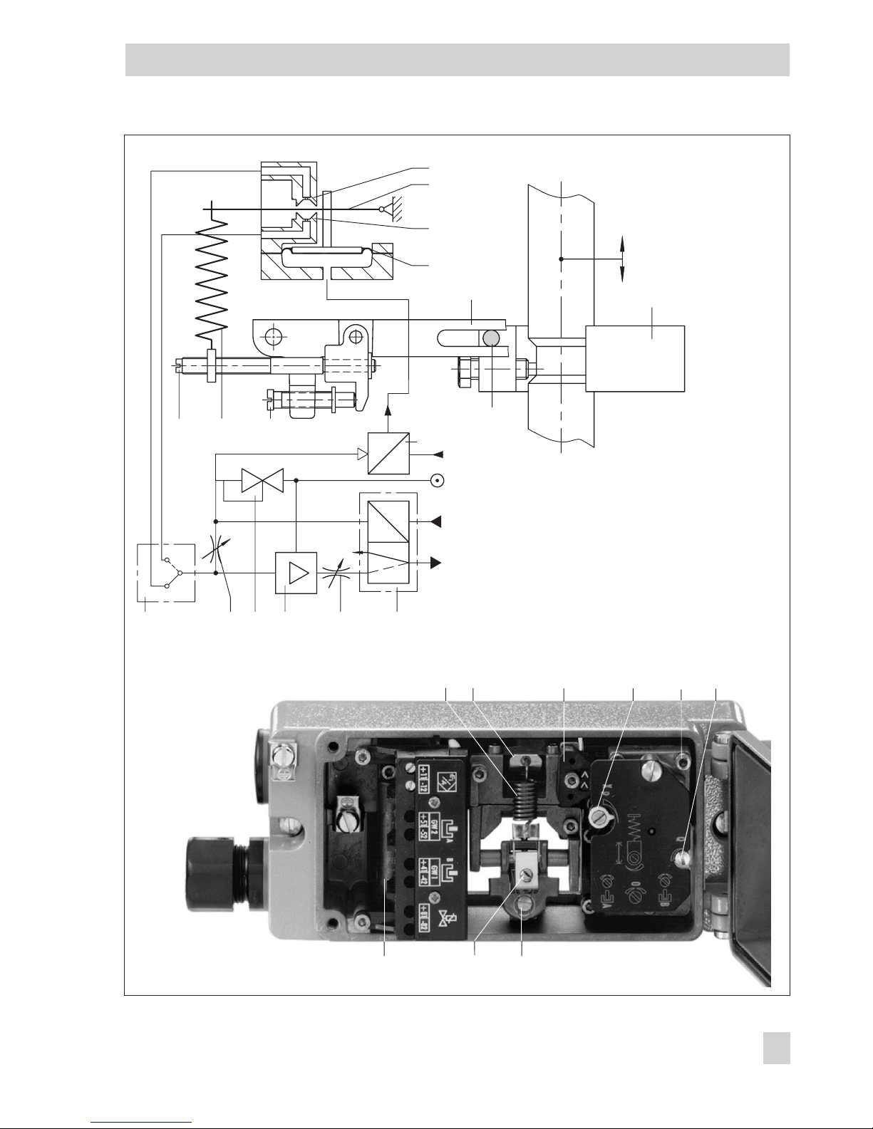
The positioner consists of an electro-
pneumatic converter unit (i/p converter) and
a pneumatic unit equipped with a lever for
travel pick-up, a measuring diaphragm, and
the pneumatic control system with nozzle,
diaphragm lever (flapper plate) and booster.
The positioner is designed either for direct
attachment to SAMSON Type 3277 Actua-
tors or for attachment according to NAMUR
(IEC 60534-6) with an adapter housing.
The positioner can be additionally equipped
with either inductive limit switches and/or a
solenoid valve or a position transmitter.
The DC control signal, e.g. 4 to 20 mA, is-
sued by the control unit is transmitted to the
electropneumatic conversion unit (13) where
it is converted into a proportional pressure
signal pe.
The positioner operates according to the
force-balance principle. The valve travel, i.e.
the valve position, is transmitted to the
pick-up lever (1) over the pin (1.1) and de-
termines the force of the measuring spring
(4). This force is compared to the positioning
force generated by the pressure peat the
measuring diaphragm (5).
If either the control signal or the valve posi-
tion changes, the diaphragm lever (3)
moves, altering the distance to the nozzle
(2.1 or 2.2), depending on the set operating
direction of the positioner.
The air is supplied to the booster (10) and
the pressure regulator (9). The controlled
supply air is fed to the i/p module, then
flows through the Xprestriction (8) and the
nozzle (2.1, 2.2) to finally stream on the di-
aphragm lever (flapper plate). Any change
in the reference variable or the valve stem
position cause the pressure to change up-
stream or downstream of the booster. The
air controlled by the booster (signal pressure
pst) flows through the volume restriction (11)
to the pneumatic actuator, causing the plug
stem to move to a position corresponding to
the DC input signal (reference variable).
The adjustable Xprestriction (8) and volume
restriction (11) are used to optimize the
positioner control loop. The pick-up lever (1)
and the range spring (4) must be selected to
match the rated valve travel and the nominal
span of the reference variable.
Positioner with inductive limit switches
In this version, the rotary shaft of the
positioner carries two adjustable tags which
actuate the built-in proximity switches.
Positioner with solenoid valve
When the positioner is equipped with a so-
lenoid valve, the control valve can be moved
to the fail-safe position regardless of the
positioner's output signal. If a control signal
corresponding to the binary signal "0" (off)
is applied to the input, the signal pressure
pst is shut off and the actuator is vented. The
actuator springs move the control valve to its
fail-safe position. If a control signal corre-
sponding to the binary signal "1" (on) is ap-
plied to the input, the signal pressure pst is
supplied to the actuator. The control valve is
in control operation.
4EB 8355-2 EN
Design and principle of operation