TLV VC2 User manual

172-65164MA-08 (VC Series) 27 December 2017
Automatic Air Vent
VC2 / VC3 / VC4
Copyright © 2017 by TLV CO., LTD.
All rights reserved

172-65164MA-08 (VC Series) 27 Dec 2017
1
Contents
Introduction ........................................................................ 1
Safety Considerations........................................................ 2
Features............................................................................. 4
Operation ........................................................................... 4
Specifications..................................................................... 5
Configuration...................................................................... 5
Installation.......................................................................... 6
Maintenance....................................................................... 7
Disassembly / Reassembly................................................ 8
Troubleshooting ............................................................... 10
Product Warranty ............................................................. 11
Introduction
Thank you for purchasing the VC series automatic air vent.
This product has been thoroughly inspected before being shipped from the
factory. When the product is delivered, before doing anything else, check the
specifications and external appearance to make sure nothing is out of the
ordinary. Also be sure to read this manual carefully before use and follow the
instructions to be sure of using the product properly.
The VC series automatic air vents are designed to automatically discharge /
release air trapped in water-carrying pipes during water transport. They also
automatically discharge the air that was entrained in the water during operation
and has subsequently been separated and collected in specific locations in the
piping.
If detailed instructions for special order specifications or options not contained in
this manual are required, please contact for full details.
This instruction manual is intended for use with the model(s) listed on the front
cover. It is necessary not only for installation, but for subsequent maintenance,
disassembly/reassembly and troubleshooting. Please keep it in a safe place for
future reference.

172-65164MA-08 (VC Series) 27 Dec 2017
2
Safety Considerations
•Read this section carefully before use and be sure to follow the instructions.
•Installation, inspection, maintenance, repairs, disassembly, adjustment and
valve opening/closing should be carried out only by trained maintenance
personnel.
•The precautions listed in this manual are designed to ensure safety and
prevent equipment damage and personal injury. For situations that may
occur as a result of erroneous handling, three different types of cautionary
items are used to indicate the degree of urgency and the scale of potential
damage and danger: DANGER, WARNING and CAUTION.
•The three types of cautionary items above are very important for safety: be
sure to observe all of them as they relate to installation, use, maintenance
and repair. Furthermore, TLV accepts no responsibility for any accidents or
damage occurring as a result of failure to observe these precautions.
Symbols
Indicates a DANGER, WARNING or CAUTION item.
DANGER
Indicates an urgent situation which poses a threat of death or serious
injury
WARNING
Indicates that there is a potential threat of death or serious injury
CAUTION
Indicates that there is a possibility of injury or equipment / product
damage
WARNING
DO NOT use for toxic, flammable or otherwise hazardous fluids.
This product is an air vent that discharges air from water piping
system. Use only for water and/or air. This product is for intended use
only. Improper use may result in such hazards as damage to the
product or malfunctions that may lead to serious accidents.
NEVER apply direct heat to the float.
The float may explode due to increased internal pressure, causing
accidents leading to serious injury or damage to property and
equipment.
CAUTION
Install properly and DO NOT use this product outside the
recommended operating pressure, temperature and other
specification ranges.
Improper use may result in such hazards as damage to the product or
malfunctions that may lead to serious accidents. Local regulations may
restrict the use of this product to below the conditions quoted.
DO NOT use this product in excess of the maximum operating
pressure differential.
Such use could make discharge impossible (blocked).
Take measures to prevent people from coming into direct contact
with product outlets.
Failure to do so may result in burns or other injury from the discharge
of fluids.
Safety considerations are continued on the next page.

172-65164MA-08 (VC Series) 27 Dec 2017
3
CAUTION
When disassembling or removing the product, wait until the
internal pressure equals atmospheric pressure and the surface of
the product has cooled to room temperature.
Disassembling or removing the product when it is hot or under
pressure may lead to discharge of fluids, causing burns, other injuries
or damage.
Be sure to use only the recommended components when
repairing the product, and NEVER attempt to modify the product
in any way.
Failure to observe these precautions may result in damage to the
product and burns or other injury due to malfunction or the discharge
of fluids.
Do not use excessive force when connecting threaded pipes to
the product.
Over-tightening may cause breakage leading to fluid discharge, which
may cause burns or other injury.
Use only under conditions in which no freeze-up will occur.
Freezing may damage the product, leading to fluid discharge, which
may cause burns or other injury.
Use only under conditions in which no water hammer will occur.
The impact of water hammer may damage the product, leading to fluid
discharge, which may cause burns or other injury.

172-65164MA-08 (VC Series) 27 Dec 2017
4
Features
1. The air vent has no hinges or levers: the only moving part is the precision-ground
float, which eliminates concentrated wear and provides long service life.
2. Simple construction with few parts allows for easy maintenance.
3. The air vent is small and light.
Operation
Take measures to prevent people from coming into direct contact with
product outlets. Failure to do so may result in burns or other injury from
the discharge of fluids.
CAUTION
1. When water is transported, air inside the piping is
forced into the air vent by the pressure of the flow.
The float inside the air vent is in the lower position, thus
the valve is fully open and allows the air that enters the
air vent and fills the area around the float to then be
discharged.
2. When discharge is completed, as water flows into the
air vent, the rising water level causes the float to rise
and to close the valve..
If there is a rapid rise in water level (caused by rapidly
opening a shut-off valve, etc.), a small amount of water
may leak with discharged air immediately before the air
vent closes.
3. If air enters the air vent while the water is causing the
valve to be closed, the air causes the water level to
drop, thus the float loses buoyancy and the valve
opens. After the air is discharged, the water level once
again rises and the valve again becomes closed.
In this manner, the air vent constantly responds to the
amount of water flow by automatically adjusting
discharge.
4. When draining the piping, the air vent automatically
opens to introduce air and remove water more easily
(preventing a vacuum from forming in the piping).
Air
Water

172-65164MA-08 (VC Series) 27 Dec 2017
5
Specifications
DO NOT use for toxic, flammable or otherwise hazardous fluids.
This product is an air vent that discharges air from water piping system.
Use only for water and/or air. This product is for intended use only.
Improper use may result in such hazards as damage to the product or
malfunctions that may lead to serious accident.
WARNING
Install properly and DO NOT use this product outside the recommended
operating pressure, temperature and other specification ranges.
Improper use may result in such hazards as damage to the product or
malfunctions which may lead to serious accidents. Local regulations
may restrict the use of this product to below the conditions quoted.
CAUTION
DO NOT use this product in excess of the maximum operating pressure
differential; such use could make discharge impossible (blocked).
CAUTION
Use only under conditions in which no freeze-up will occur. Freezing
may damage the product, leading to fluid discharge, which may cause
burns or other injury.
CAUTION
Refer to the product nameplate for detailed specifications.
Model
Production Lot No.
Maximum Allowable
Temperature (TMA)*
Maximum Operating
Temperature (TMO)
Nominal Diameter
Valve No.**
Maximum Allowable
Pressure*
Maximum Operating
Pressure
* Maximum allowable pressure (PMA) and maximum allowable temperature (TMA) are
PRESSURE SHELL DESIGN CONDITIONS, NOT OPERATING CONDITIONS.
** Valve No. is displayed for products with options. This item is omitted from the nameplate
when there are no options.
Configuration
VC2
VC3
VC4
No.
Part Name
1
Body
2
Cover
3
Float
4
Valve Seat
5
Cover Gasket
6
Nameplate
No.
Part Name
1
Body
2
Cover
3
Float
4
Valve Seat
5
Cover Gasket
6
Valve Seat Gasket
7
Nameplate
No.
Part Name
1
Body
2
Cover
3
Float
4
Valve Seat
5
Cover Gasket
6
Valve Seat Gasket
7
Cover Bolt
8
Nameplate
172-65164MA-08 (VC Series) 27 Dec 2017
6
Installation
DO NOT use for toxic, flammable or otherwise hazardous fluids.
This product is an air vent that discharges air from water piping system.
Use only for water and/or air. This product is for intended use only.
Improper use may result in such hazards as damage to the product or
malfunctions that may lead to serious accident.
WARNING
Install properly and DO NOT use this product outside the recommended
operating pressure, temperature and other specification ranges.
Improper use may result in such hazards as damage to the product or
malfunctions which may lead to serious accidents. Local regulations
may restrict the use of this product to below the conditions quoted.
CAUTION
Take measures to prevent people from coming into direct contact with
product outlets. Failure to do so may result in burns or other injury from
the discharge of fluids.
CAUTION
Do not use excessive force when connecting threaded pipes to the
product. Over-tightening may cause breakage leading to fluid
discharge, which may cause burns or other injury.
CAUTION
Installation, inspection, maintenance, repairs, disassembly, adjustment and valve
opening/closing should be carried out only by trained maintenance personnel.
1. Before installation, be sure to remove all protective seals.
2. Before installing the product, open the inlet valve and blow out the piping to remove
any piping scraps, dirt and oil. Close the inlet valve after blowdown.
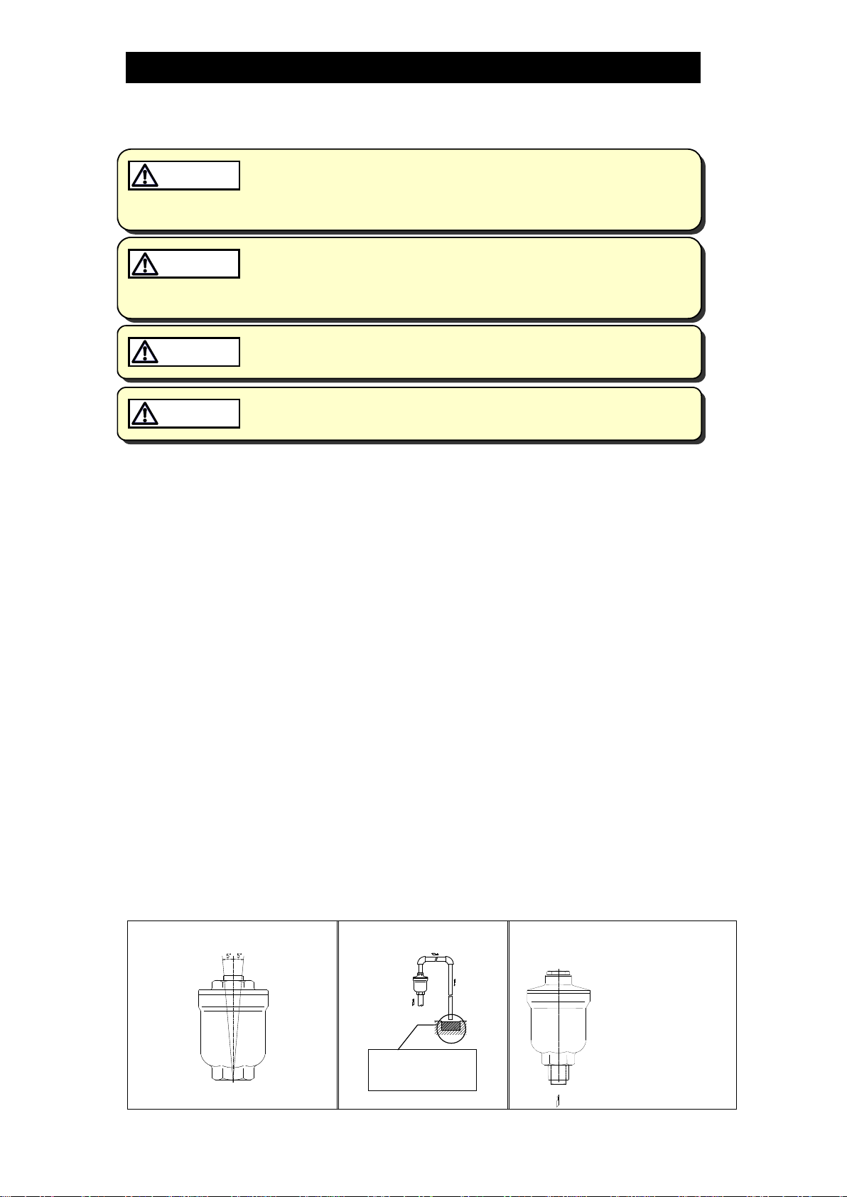
3. This product must be installed vertically, with the inlet at the bottom and the outlet at the
top, and should be inclined no more than 5° horizontally and front-to-back (Figure 1).
4. Install the product in a location where air is likely to collect, such as a bend in the piping.
5. Install outlet piping leading to a drainage vessel or ditch. Make sure the end of the
pipe is above the waterline, so that dirt and water can not be sucked up by vacuum
when the system shuts down (Figure 2).
6. Inlet piping with no horizontal portion is recommended for water/air displacement. If
there is a horizontal portion, make the pipe diameter of the horizontal portion larger
than the vertical portion or make the horizontal portion as short as possible.
7. Make sure the inlet piping diameter is at least as large as the product’s inlet diameter.
For the inlet connection especially for the VC2 which has a nominal diameter of
15 mm (1/2in), use a pipe/fitting, etc. with an inner diameter of at least 16 mm (5/8in),
such as a schedule 40 pipe nipple with a nominal diameter of 15 mm (1/2in).
A smaller pipe may prevent water/air displacement (Figure 3).
8. Installation of an isolation valve just before the product’s main connection is
recommended as it enables maintenance during operation. A full-bore ball valve is
recommended.
9. Make sure to take measures to prevent foreign matter from flowing into the product.
If there is a problem, determine the cause using the “Troubleshooting” section in this manual.
Figure 1
Tolerance Angle for Installation
-5°
Figure 2
Outlet Piping Installation
Make sure the end
of the pipe is above
the waterline
Figure 3
Inner Diameter of Inlet Pipe and
Fittings for VC2
min. Φ16 mm (5/8in)

172-65164MA-08 (VC Series) 27 Dec 2017
7
Maintenance
Take measures to prevent people from coming into direct contact with
product outlets. Failure to do so may result in burns or other injury from
the discharge of fluids.
CAUTION
Be sure to use only the recommended components when repairing the
product, and NEVER attempt to modify the product in any way. Failure to
observe these precautions may result in damage to the product or burns
or other injury due to malfunction or the discharge of fluids.
CAUTION
Operational Check
A visual inspection of the following items should be done on a daily basis to determine
whether the air vent is operating properly or has failed.
If the air vent should fail, it may cause water leakage or hindrance to water flow.
Normal
:
Air is discharged as it accumulates, with the air vent
closing (with no leakage) when no air is present in the
piping.
Blocked
(Discharge Impossible)
:
No air is discharged though air accumulates in the air
vent.
Leakage
:
Water is discharged or leaks through the air vent outlet
during closed position.
Parts Inspection
When parts have been removed, or during periodic inspections, use the following table
to inspect the parts and replace any that are found to be defective.
Procedure
Gasket(s):
check for warping and damage
Valve Seat:
check for scratches or wear
Float:
check for scratches or dents

172-65164MA-08 (VC Series) 27 Dec 2017
8
Disassembly / Reassembly
NEVER apply direct heat to the float. The float may explode due to
increased internal pressure, causing accidents leading to serious injury
or damage to property and equipment.
WARNING
When disassembling or removing the product, wait until the internal
pressure equals atmospheric pressure and the surface of the product
has cooled to room temperature. Disassembling or removing the
product when it is hot or under pressure may lead to discharge of fluids,
causing burns, other injuries or damage.
CAUTION
Be sure to use only the recommended components when repairing the
product, and NEVER attempt to modify the product in any way. Failure to
observe these precautions may result in damage to the product or burns
or other injury due to malfunction or the discharge of fluids.
CAUTION
Use the following procedures to remove components. Use the same procedures in
reverse to reassemble. (Installation, inspection, maintenance, repairs, disassembly,
adjustment and valve opening/closing should be carried out only by trained
maintenance personnel.)
Disassembly / Reassembly
Part
During Disassembly
During Reassembly
Cover
Clamp the hexagonal part of the vent
body in a vice and use a wrench to
loosen the cover (For the VC4,
remove the cover bolt with a wrench)
Consult the table of tightening torques and
tighten to the proper torque
Valve Seat
The surface is polished; remove,
being careful not to scratch the
seating surface
(For the VC2, push it inwards from
the outlet side, being careful not to
scratch it)
Replace with a new valve seat if misshapen
or damaged
Consult the table of tightening torques and
tighten to the proper torque
(For the VC2, push it into place from the
interior side of the cover using a finger)
Gasket
Remove and clean sealing surface
Replace with a new gasket if damaged
Float
Remove, being careful not to scratch
the surface
Insert, being careful not to scratch the
surface
Table of Tightening Torques
Model Part Name
Torque
Distance Across Flats
N∙m
(lbf·ft)
mm
(in)
VC2
Cover
100
(73)
24
(15/16)
VC3
Cover
200
(150)
46
(113/16)
Valve Seat
15
(11)
14
(9/16)
VC4
Cover Bolt
80
(59)
19
(3/4)
Valve Seat
15
(11)
14
(9/16)
(1 N⋅m ≈10 kg⋅cm)
NOTE: If drawings or other special documentation were supplied for the product, any torque
given there takes precedence over values shown here.

172-65164MA-08 (VC Series) 27 Dec 2017
9
Exploded View
Cover
Cover Gasket
Valve Seat Gasket
Valve Seat
Cover Bolt
Cover Gasket
Float Valve Seat
Float
Body Body
VC2 VC3 VC4

172-65164MA-08 (VC Series) 27 Dec 2017
10
Troubleshooting
NEVER apply direct heat to the float. The float may explode due to
increased internal pressure, causing accidents leading to serious injury
or damage to property and equipment.
WARNING
When disassembling or removing the product, wait until the internal
pressure equals atmospheric pressure and the surface of the product
has cooled to room temperature. Disassembling or removing the
product when it is hot or under pressure may lead to discharge of fluids,
causing burns, other injuries or damage.
CAUTION
When the product fails to operate properly, use the following table to locate the cause
and remedy.
Problem
Cause
Remedy
No air is
discharged or
discharge is poor
The trapped air cannot displace the
water in the piping
Correct the inlet piping
(Inner diameter should be at least
16mm (
5
/8in))
The valve seat is clogged with dirt or
foreign matter
Clean the valve seat
The inlet or outlet piping is clogged
Clean the piping
The operating pressure exceeds the
maximum specified pressure for this
product
Replace the air vent with a model that
has a suitable operating pressure
rating
Water leaks when
the vent is closed
There is a build-up of rust or scale on
the valve seat or the valve seat is
damaged
Clean the valve seat or replace with a
new valve seat
The float is misshapen, dirty or has a
film build-up
Clean the float or replace with a new
float
The installation angle of inclination is
incorrect
Correct the installation
The vent does not
close and water is
blowing
The float is damaged or filled with
water
Replace with a new float
The specific gravity of the liquid is
outside the specifications for this
product (this product is for water
systems)
Select a product with suitable
specifications for the operating
conditions

172-65164MA-08 (VC Series) 27 Dec 2017
11
Product Warranty
1. Warranty Period
One year following product delivery.
2. Warranty Coverage
TLV CO., LTD. warrants this product to the original purchaser to be free from
defective materials and workmanship. Under this warranty, the product will be
repaired or replaced at our option, without charge for parts or labor.
3. This product warranty will not apply to cosmetic defects, nor to any product
whose exterior has been damaged or defaced; nor does it apply in the
following cases:
1) Malfunctions due to improper installation, use, handling, etc., by other than
TLV CO., LTD. authorized service representatives.
2) Malfunctions due to dirt, scale, rust, etc.
3) Malfunctions due to improper disassembly and reassembly, or inadequate
inspection and maintenance by other than TLV CO., LTD. authorized
service representatives.
4) Malfunctions due to disasters or forces of nature.
5) Accidents or malfunctions due to any other cause beyond the control of
TLV CO., LTD.
4. Under no circumstances will TLV CO., LTD. be liable for consequential
economic loss damage or consequential damage to property.
* * * * * * *
For Service or Technical Assistance:
Contact your representative or your regional office.
Manufacturer
881 Nagasuna, Noguchi
Kakogawa, Hyogo 675-8511, JAPAN
Tel: 81 - (0)79 - 427 - 1800
This manual suits for next models
2
Table of contents


 instruction manual")


