TLV SF1 User manual

172-65387MA-08 (SF1 Separator Filter) 1 October 2021
Separator Filter
SF1
Copyright © 2021 by TLV CO., LTD.
All rights reserved

172-65387MA-08 (SF1 Separator Filter) 1 Oct 2021
1
Contents
Introduction ....................................................................... 1
Safety Considerations....................................................... 2
Specifications.................................................................... 4
Configuration..................................................................... 5
Installation......................................................................... 6
For Longer Filter Life......................................................... 8
To Minimize Pressure Loss Effects................................... 9
Maintenance.................................................................... 10
Disassembly/Reassembly............................................... 11
Troubleshooting .............................................................. 13
TLV EXPRESS LIMITED WARRANTY........................... 14
Service ............................................................................ 16
Introduction
Thank you for purchasing theTLV separator filter.
This product has been thoroughly inspected before being shipped from the
factory. When the product is delivered, before doing anything else, check the
specifications and external appearance to make sure nothing is out of the
ordinary. Also be sure to read this manual carefully before use and follow the
instructions to be sure of using the product properly.
The SF1 separator filter combines a high-performance filter with a cyclone
separator that removes dirt, scale and condensate (entrained moisture) by
means of centrifugal force and gravity. The SF1 can be used for both
separator and filter applications. It is suitable for use in steam and air mains,
and in applications calling for high-quality steam and air.
If detailed instructions for special order specifications or options not contained
in this manual are required, please contactTLV for full details.
This instruction manual is intended for use with the model(s) listed on the front
cover. It is necessary not only for installation, but for subsequent
maintenance, disassembly/reassembly and troubleshooting. Please keep it in
a safe place for future reference.
172-65387MA-08 (SF1 Separator Filter) 1 Oct 2021
2
Safety Considerations
Read this section carefully before use and be sure to follow the instructions.
Installation, inspection, maintenance, repairs, disassembly, adjustment and valve
opening/closing should be carried out only by trained maintenance personnel.
The precautions listed in this manual are designed to ensure safety and prevent
equipment damage and personal injury. For situations that may occur as a result of
erroneous handling, three different types of cautionary items are used to indicate
the degree of urgency and the scale of potential damage and danger: DANGER,
WARNING and CAUTION.
The three types of cautionary items above are very important for safety: be sure to
observe all of them as they relate to installation, use, maintenance and repair.
Furthermore, TLV accepts no responsibility for any accidents or damage occurring
as a result of failure to observe these precautions.
Symbols
Indicates a DANGER, WARNING or CAUTION item.
Indicates an urgent situation which poses a threat of death or
serious injury
Indicates that there is a potential threat of death or serious injury
Indicates that there is a possibility of injury or equipment/product
damage
Install properly and DO NOT use this product outside the
recommended operating pressure, temperature and other
specification ranges.
Improper use may result in such hazards as damage to the product
or malfunctions that may lead to serious accidents. Local
regulations may restrict the use of this product to below the
conditions quoted.
Use hoisting equipment for heavy objects (weighing
approximately 20 kg (44 lb) or more).
Failure to do so may result in back strain or other injury if the object
should fall.
Make sure the nut on the body clamp is fully tightened.
Failure to do so may result in burns or other injury from the
discharge of fluids.
When disassembling or removing the product, wait until the
internal pressure equals atmospheric pressure and the surface
of the product has cooled to room temperature.
Disassembling or removing the product when it is hot or under
pressure may lead to discharge of fluids, causing burns, other
injuries or damage.
Continued on the next page
DANGER
WARNING
CAUTION
CAUTION
172-65387MA-08 (SF1 Separator Filter) 1 Oct 2021
3
Be sure to use only the recommended components when
repairing the product, and NEVER attempt to modify the
product in any way.
Failure to observe these precautions may result in damage to the
product and burns or other injury due to malfunction or the
discharge of fluids.
Do not use excessive force when connecting threaded pipes
to the product.
Over-tightening may cause breakage leading to fluid discharge,
which may cause burns or other injury.
Use only under conditions in which no freeze-up will occur.
Freezing may damage the product, leading to fluid discharge,
which may cause burns or other injury.
Use only under conditions in which no water hammer will
occur.
The impact of water hammer may damage the product, leading to
fluid discharge, which may cause burns or other injury.
CAUTION
172-65387MA-08 (SF1 Separator Filter) 1 Oct 2021
4
Specifications
Install properly and DO NOT use this product outside the recommended
operating pressure, temperature and other specification ranges.
Improper use may result in such hazards as damage to the product or
malfunctions that may lead to serious accidents. Local regulations may restrict
the use of this product to below the conditions quoted.
Use only under conditions in which no freeze-up will occur.
Freezing may damage the product, leading to fluid discharge, which may cause
burns or other injury.
Refer to the product nameplate for detailed specifications.
A
Model
B
Nominal Diameter
C
Maximum Allowable Pressure (PMA)*
D
Maximum Allowable Temperature (TMA)*
E
Maximum Operating Pressure (PMO)
F
Maximum Operating Temperature (TMO)
G
Production Lot No.
H
Valve No.**
The filter grade (m) is indicated by numbers at the end of the model name and on the bottom
of the filter.
* Maximum allowable pressure (PMA) and maximum allowable temperature (TMA) are
PRESSURE SHELL DESIGN CONDITIONS, NOT OPERATING CONDITIONS.
** Valve No. is displayed for products with options. This item is omitted from the
nameplate when there are no options.
CAUTION
172-65387MA-08 (SF1 Separator Filter) 1 Oct 2021
5
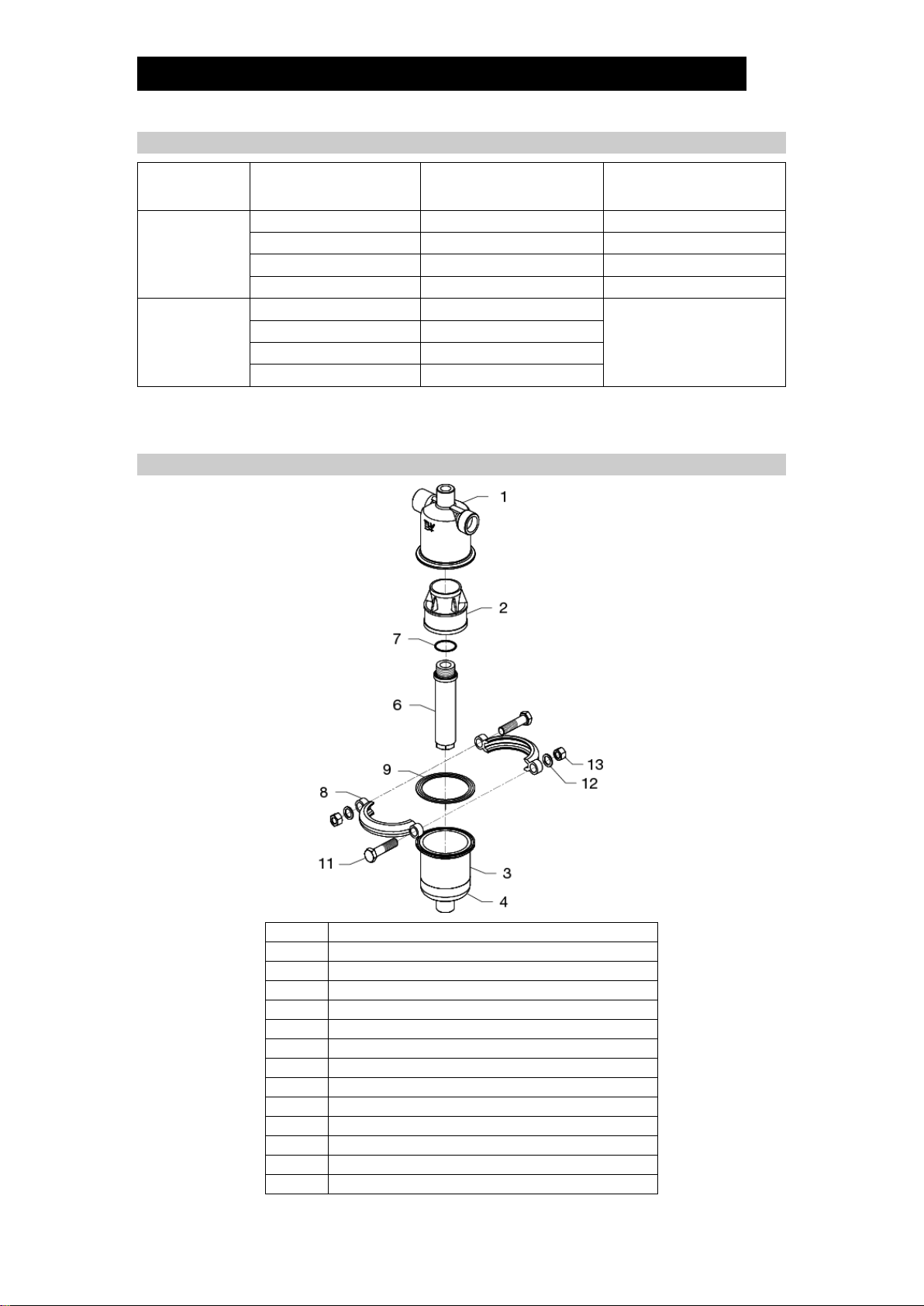
Configuration
No.
Part Name
1
Body
2
Separator
3
Separator Body
4
Separator Bottom
5
Baffle
6
Filter
7
Filter Gasket
8
Body Clamp
9
Body Gasket
10
Nameplate
11
Clamp Bolt
12
Spring Washer
13
Clamp Nut
172-65387MA-08 (SF1 Separator Filter) 1 Oct 2021
6
Installation
Install properly and DO NOT use this product outside the recommended
operating pressure, temperature and other specification ranges.
Improper use may result in such hazards as damage to the product or
malfunctions that may lead to serious accidents. Local regulations may restrict
the use of this product to below the conditions quoted.
Use hoisting equipment for heavy objects (weighing approximately 20 kg
(44 lb) or more).
Failure to do so may result in back strain or other injury if the object should fall.
Make sure the nut on the body clamp is fully tightened.
Failure to do so may result in burns or other injury from the discharge of fluids.
Take measures to prevent people from coming into direct contact with
product outlets.
Failure to do so may result in burns or other injury from the discharge of fluids.
Installation, inspection, maintenance, repairs, disassembly, adjustment and valve
opening/closing should be carried out only by trained maintenance personnel.
1. Ensure the filter grade (m) is correct by checking the numbers at the end of the
model name on the nameplate and on the bottom of the filter.
2. Before installation, be sure to remove all protective seals.
3. Install the product in a location where the removal and filtration of entrained dirt,
scale and condensate would be most effective. (For example, on a main or
branch at the inlet of equipment requiring high-quality dry steam.)
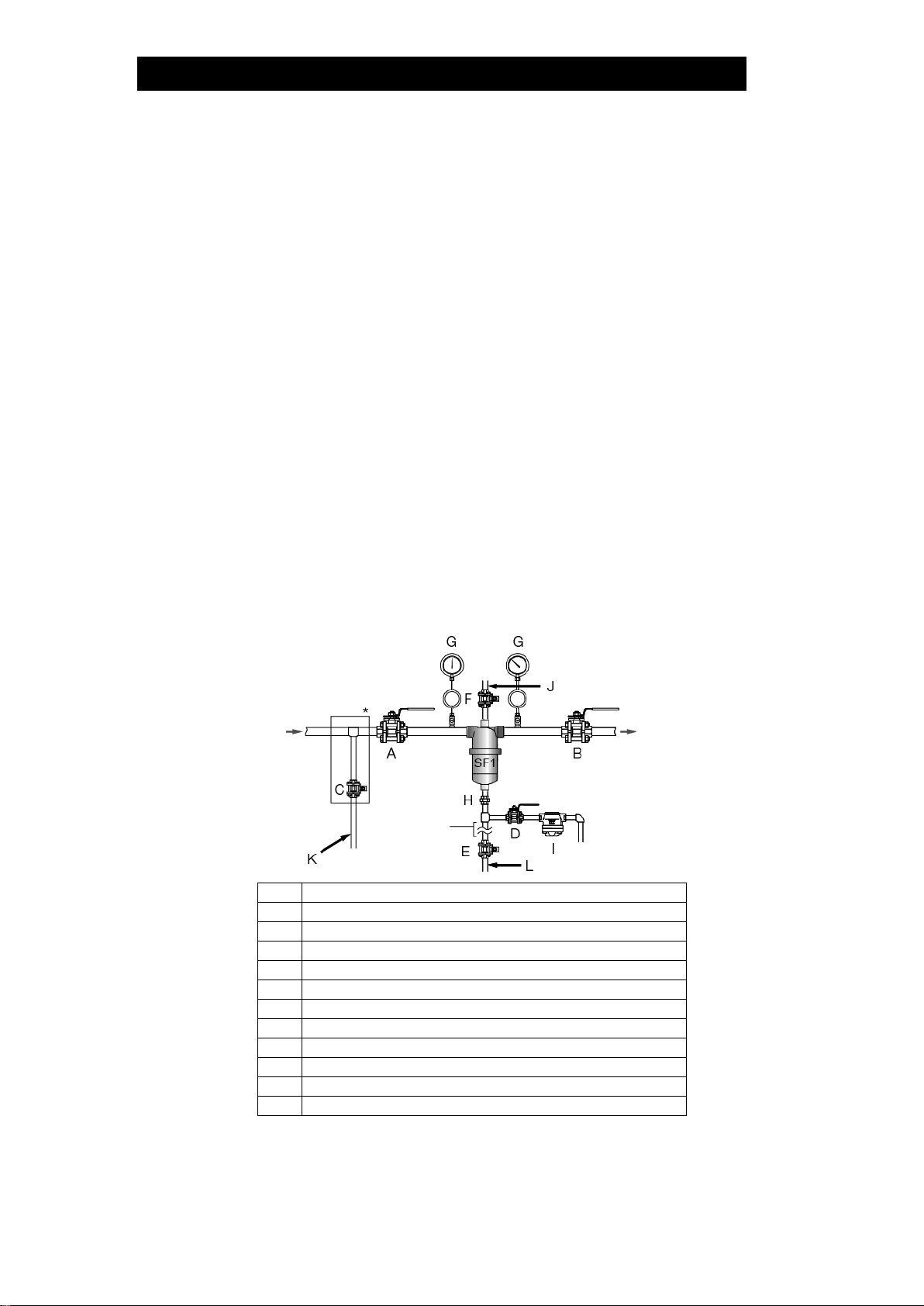
4. Install valves (A) (B) at the inlet and outlet of the separator filter and a piping
blowdown pipe/valve (C) before the inlet valve (A). (See the "Typical Piping Flow"
diagram in the "For Longer Filter Life"section.)
5. Before using the product, close the inlet valve (A), open the piping blowdown
valve (C) and blow out the piping to remove any piping scraps, dirt and oil. Close
the piping blowdown valve (C) when finished. (See the "Typical Piping Flow"
diagram in the "For Longer Filter Life"section.)
6. Install pressure gauges at the separator filter inlet and separator filter outlet or the
pressure detection port in order to monitor the pressure differential.
7. Install the product so the arrow on the body is pointing in the direction of steam or
air flow and the condensate outlet is on the bottom.
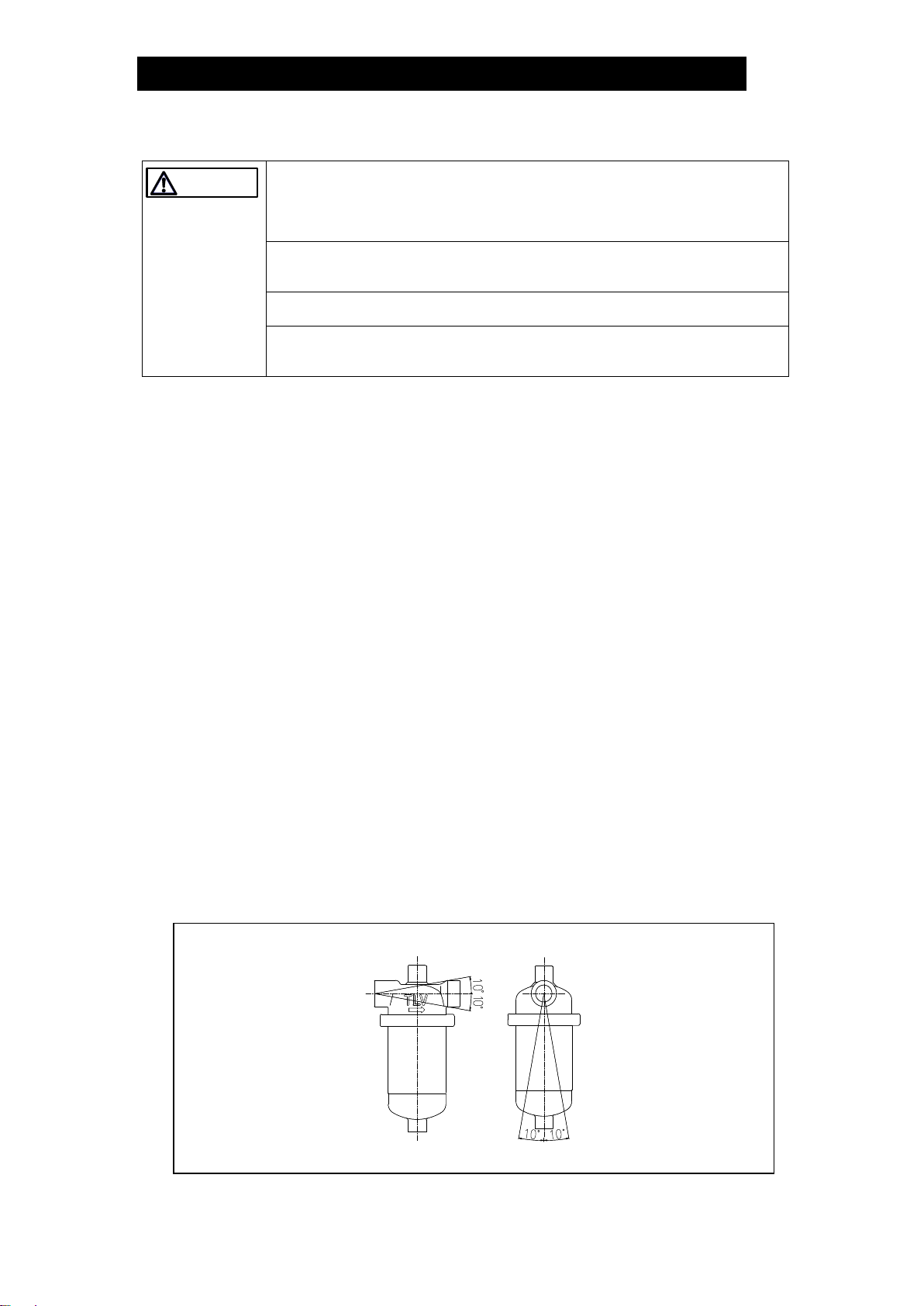
8. The product must be installed horizontally and with no more than 10° inclination
horizontally and front-to-back.
Tolerance Angle for Installation: 10°
The product should be installed so that the letters TLV on the body are horizontal.
CAUTION
172-65387MA-08 (SF1 Separator Filter) 1 Oct 2021
7
9. Install discharge piping from the condensate discharge port, including a vertical
union, dirt/scale collection piping, piping blowdown valve (E) and horizontal piping
with steam, air or drain trap and an inlet valve (D) for the trap. (See the "Typical
Piping Flow"diagram in the "For Longer Filter Life"section.)
10. Make sure to install a free float trap that discharges condensate continuously
during operation along with the separator filter.
Example
SF1 Connection Size
For Steam Use
For Air Use
mm
(in)
15 –40 mm
(1/2–11/2)
SS1 Series, J3S-X, J3X
JA3, JA3D, SS1VG Series
50 mm
(2)
JH5SL, J5S-X, J5X
JA5, JAH5RG Series
NOTE: At start-up, large amounts of initial condensate are generated. Also,
during batch operation, a large amount of condensate may accumulate in
the piping when operation stops. If there are concerns that a large
amount of condensate could flow into the separator filter, make sure to
install a piping blowdown valve at the inlet of the separator filter to ensure
that the condensate is eliminated, or install a steam trap with sufficient
discharge capacity even when the pressure differential is extremely low.
(See "For Longer Filter Life"items 1, 2 and 3.)
11. Close the dirt/scale blowdown valve (E) below the dirt/scale collection piping,
open the separator filter inlet valve (A), outlet valve (B) and the trap inlet valve
(D), and ensure that the separator filter functions properly. (See the "Typical
Piping Flow"diagram in the "For Longer Filter Life"section.)
12. After letting some live steam/air enter the filter, allow the separator filter to cool to
ambient temperature, and then tighten the clamp further.
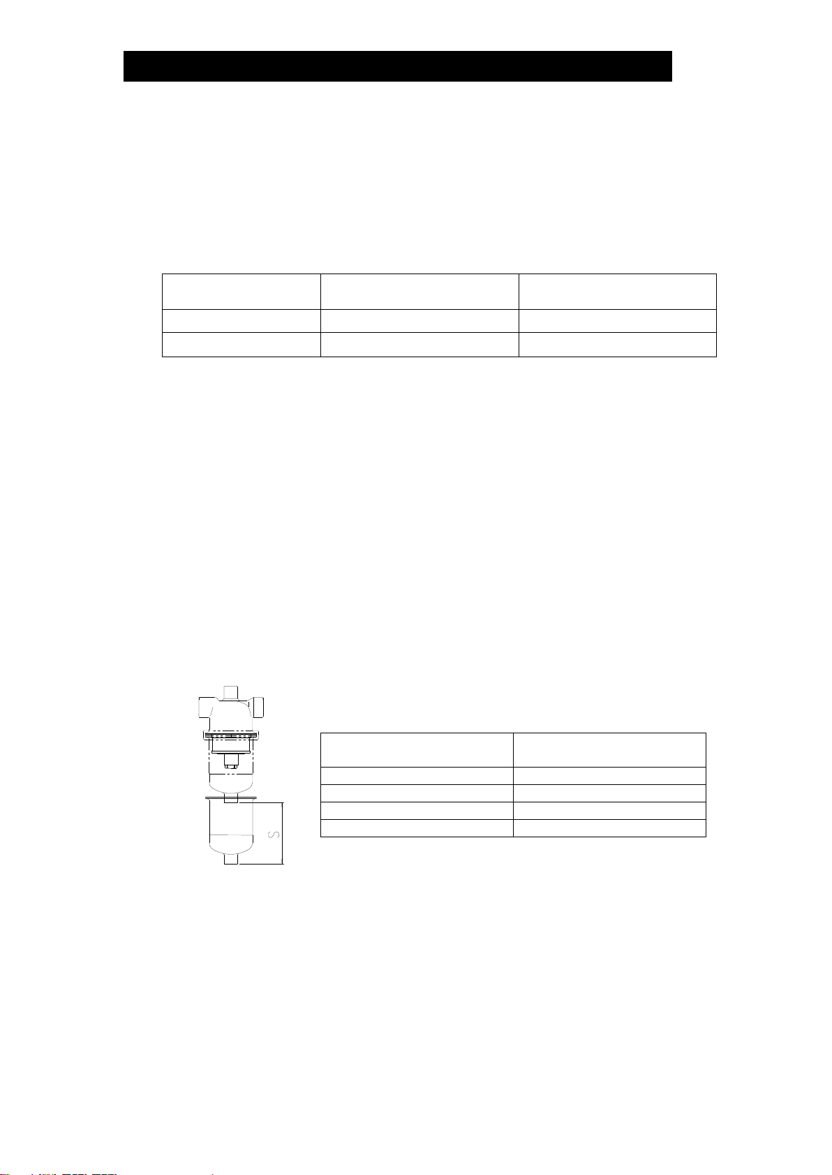
Ensure the maintenance space is sufficient for maintenance (i.e. replacement of
internal filter).
SF1 Connection Size
Min. Maintenance Space (S)
mm
(in)
mm
(in)
15, 20
(1/2,3/4)
100
(4)
25
(1)
150
(6)
40
(11/2)
300
(12)
50
(2)
350
(14)
If there is a problem, determine the cause using the "Troubleshooting"section of this
manual.
172-65387MA-08 (SF1 Separator Filter) 1 Oct 2021
8
For Longer Filter Life
Make sure to perform the following to prevent the inflow of a large amount of
condensate during start-up. (See the "Typical Piping Flow"diagram below.)
1. Operate inlet valve (A) being careful not to open it quickly.
2. If condensate accumulates when inlet valve (A) is closed, open blowdown valve
(C) to blow it out.
3. If a blowdown valve has not been installed, a steam trap with sufficient discharge
capacity even when the pressure differential is extremely low must be installed on
the separator filter inlet side considering the initial condensate amount.
4. The trap outlet piping should not be located close to other trap outlet piping or
backflow may occur. If other outlet piping is close by, install check valves close to
each trap outlet.
5. If the trap outlet piping is raised, install a check valve close to the trap outlet to
prevent backflow of condensate when the equipment stops.
6. The trap outlet pipe end should not be under water. If it must be under water,
install a check valve close to the trap outlet or make a small hole in the outlet
piping to prevent backflow of water due to vacuum formation inside the piping.
Typical Piping Flow
A
Inlet Valve
B
Outlet Valve
C
Blowdown Valve
D
Trap Inlet Valve
E
Dirt/Scale Blowdown Valve
F
Valve
G
Pressure Gauge
H
Union
I
Steam Trap
J
Washing (hot/cold water, steam or air)
K
Blowdown/condensate discharge
L
Dirt and scale blowdown
* Ahead of the inlet valve for the SF1, install a valve for piping blowdown or a steam trap with
sufficient discharge capacity when differential pressure is extremely low.

172-65387MA-08 (SF1 Separator Filter) 1 Oct 2021
9
To Minimize Pressure Loss Effects
Pressure loss across the separator filter increases the longer it is in service, resulting
in a continuous decrease in secondary pressure. If a slight drop in secondary
pressure will affect the process, refer to the "In cases where more stable pressure is
needed" piping flow diagram shown below.
The effects of gradually increasing pressure loss can be minimized. However, this
does not mean that the service life of the clogging filter can be prolonged.
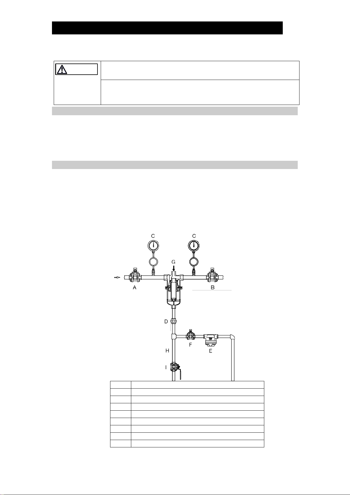
In cases where more stable pressure is needed
Installing a COSPECT pressure reducing valve* with an external pressure sensing
line from the outlet of the SF1 will help supply stable pressure and minimize pressure
drop, which gradually increases due to build-up of dirt/scale at the filter.
1. When dirt and scale build up, SF1 outlet pressure drops.
2. Pressure reducing valve detects the pressure drop and automatically increases
SF1 inlet pressure.
3. The SF1 outlet pressure rises to maintain set pressure**.
*If a pressure reducing valve other than COSPECT (with built-in strainer, separator, and
steam trap) is installed, a pipe tee and piping with a valve for condensate discharge must be
installed ahead of the pressure reducing valve for the SF1 inlet.
** If it becomes impossible to adjust the pressure with the pressure reducing valve due to
build-up of dirt/scale, clean or replace the filter.
A
Inlet Valve
B
Outlet Valve
C
Valve
D
Trap Inlet Valve
E
Dirt/Scale Blowdown Valve
F
Valve
G
Pressure Gauge
H
Union
I
Steam Trap
J
Valve
K
COSPECT Pressure Reducing Valve
L
Secondary Pressure Sensing Line
M
Washing (hot/cold water, steam or air)
N
Dirt and scale collection
O
Blowdown/condensate discharge
P
Dirt and scale blowdown
172-65387MA-08 (SF1 Separator Filter) 1 Oct 2021
10
Maintenance
Take measures to prevent people from coming into direct contact with
product outlets.
Failure to do so may result in burns or other injury from the discharge of fluids.
Be sure to use only the recommended components when repairing the
product, and NEVER attempt to modify the product in any way.
Failure to observe these precautions may result in damage to the product and
burns or other injury due to malfunction or the discharge of fluids.
Operational Check
Make sure that there is sufficient steam or air flow from the separator filter outlet by
checking the difference in inlet and outlet pressures (pressure loss) or any available
flow meters. If the differential pressure is too large (pressure loss is several times
more than when the product was new) or there is too little flow, the filter may be
clogged. Disassemble, inspect and clean the filter, or replace as necessary.
Filter Cleaning & Replacement
When cleaning is required, first use back flow cleaning by supplying hot or cold
water, steam, or air through the washing port on the top of the separator filter (details
below). When the clogging is more severe, disassemble and apply high-pressure
water cleaning, ultrasonic cleaning, acid cleaning, or other appropriate method
directly to the filter. Replace with a new filter when cleaning is ineffective. We
recommend having spare filters on hand for this purpose.
Valve Status during Backwash
A
Inlet valve is closed
B
Outlet valve is closed
C
Pressure Gauge
D
Union
E
Steam Trap
F
Trap inlet valve is closed
G
Hot/cold water, steam, or air (valve open)
H
Dirt and scale collection
I
Blowdown valve is open
CAUTION
172-65387MA-08 (SF1 Separator Filter) 1 Oct 2021
11
Disassembly/Reassembly
Use hoisting equipment for heavy objects (weighing approximately 20 kg (44
lb) or more).
Failure to do so may result in back strain or other injury if the object should fall.
When disassembling or removing the product, wait until the internal pressure
equals atmospheric pressure and the surface of the product has cooled to
room temperature.
Disassembling or removing the product when it is hot or under pressure may lead
to discharge of fluids, causing burns, other injuries or damage.
Use the following procedures to remove components. Use the same procedures in
reverse to reassemble. (Installation, inspection, maintenance, repairs, disassembly,
adjustment and valve opening/closing should be carried out only by trained maintenance
personnel.)
Removing/Reattaching the Separator Body and its Components
Part
During Disassembly
During Reassembly
Body Clamp 8
Hold the separator body so that
it will not fall; loosen the nut.
Insert the clamp bolt from the side which
has a rotation stopper.
Consult the table of tightening torques
and tighten the nut to the proper torque so
that there is no seal leakage.
Open the inlet valve and let steam/air to
enter the filter, then close the inlet valve;
after internal and atmospheric pressures
have equalized and the separator filter
body has cooled, tighten nut again.
Body 1/
Separator Body
3
Remove the clamp and pull the
separator body down and off,
being careful not to scratch the
gasket sealing surfaces
Gently rejoin being careful to insert the
raised part of the body gasket into the
housing on the body.
Reattach the body clamp
Body Gasket 9
Remove, being careful not to
scratch the sealing surfaces
Replace with a new gasket if warped or
damaged.
Place on the separator body
Disassembly/Reassembly of the Filter
Part
During Disassembly
During Reassembly
Filter 6
Remove with a wrench
NOTE:
The separator comes off with
the filter. Make sure not to
drop the separator.
Check for dents and damage, etc. to both
threads in order to prevent seizing, and
clean the threads by blowing them out with
air. Then manually screw the filter into the
body carefully until it hits the bottom. Next,
consult the table of tightening torques and
tighten to the proper torque
Coat thread portions with a small amount
of food grade anti-seize (such as “NEVER-
SEEZ PTFE White Food Grade” made by
Bostik, Inc.). Avoid using too much as anti-
seize may ooze out of the thread.
Separator 2
Remove the separator; clean
sealing surface on the separator
and body
Assemble the separator onto the body
together with the filter
Filter Gasket 7
Remove, being careful not to
scratch the surface
Replace with a new gasket if warped or
damaged
CAUTION
172-65387MA-08 (SF1 Separator Filter) 1 Oct 2021
12
Table of Tightening Torques
Part
SF1 Connection Size
Torque
Distance Across Flats
mm
(in)
Nm
(lbf·ft)
mm
(in)
Filter 6
15, 20
(1/2, 3/4)
30
(22)
32
(11/4)
25
(1)
40
(29)
36
(17/16)
40
(11/2)
50
(37)
50
(2)
50
(2)
60
(44)
60
(23/8)
Clamp nut 13
(for Body
Clamp 8)
15, 20
(1/2, 3/4)
15
(11)
Clamp Bolt: 14 (9/16)
Clamp Nut: 16 (5/8)
25
(1)
20
(15)
40
(11/2)
25
(18)
50
(2)
50
(37)
(1 Nm 10 kgcm)
NOTE: If drawings or other special documentation were supplied for the product, any torque
given there takes precedence over values shown here.
Exploded View
No.
Part Name
1
Body
2
Separator
3
Separator Body
4
Separator Bottom (fixed to Separator Body)
5
Baffle (not shown, fixed to Separator Bottom)
6
Filter
7
Filter Gasket
8
Body Clamp
9
Body Gasket
10
Nameplate (not shown)
11
Clamp Bolt
12
Spring Washer
13
Clamp Nut
172-65387MA-08 (SF1 Separator Filter) 1 Oct 2021
13
Troubleshooting
When disassembling or removing the product, wait until the internal
pressure equals atmospheric pressure and the surface of the product has
cooled to room temperature.
Disassembling or removing the product when it is hot or under pressure may
lead to discharge of fluids, causing burns, other injuries or damage.
If the product fails to operate properly, use the following table to locate the cause and
remedy.
Problem
Cause
Remedy
Matter larger than the
specified filter grade
passes through the
separator outlet
The filter grade is incorrect
Replace with a filter of the
correct grade
The filter is broken
Replace with a new filter
Outlet side steam or air
retains entrained
condensate
The flow rate is too high or
flow velocity is too fast for the
separator filter
Make corrections to the piping
to reduce flow rate and velocity
Improper installation
Correct the installation
The outlet pressure is too
low or the specified flow
rate cannot be achieved
The pressure loss through the
filter is too large
Clean or replace with a new
filter
The filter is clogged
Steam or air is leaking
between the body and
separator body
Gasket deterioration or
damage
Replace with a new gasket
The nut on the clamp is not
fully tightened
Tighten the nut to the proper
torque
CAUTION

172-65387MA-08 (SF1 Separator Filter) 1 Oct 2021
14
TLV EXPRESS LIMITED WARRANTY
Subject to the limitations set forth below, TLV CO., LTD., a Japanese corporation
(“TLV”), warrants that products which are sold by it, TLV International Inc. (“TII”) or one
of its group companies excluding TLV Corporation (a corporation of the United States of
America), (hereinafter the “Products”) are designed and manufactured by TLV, conform
to the specifications published by TLV for the corresponding part numbers (the
“Specifications”) and are free from defective workmanship and materials. The party
from whom the Products were purchased shall be known hereinafter as the “Seller”.
Withregard to products or components manufactured byunrelated third parties (the
“Components”), TLV provides no warranty other than the warranty from the third party
manufacturer(s), if any.
Exceptions to Warranty
This warranty does not cover defects or failures caused by:
1. improper shipping, installation, use, handling, etc., by persons other than TLV,
TII or TLV group company personnel, or service representatives authorized by
TLV; or
2. dirt, scale or rust, etc.; or
3. improper disassembly and reassembly, or inadequate inspection and
maintenance by persons other than TLV or TLV group company personnel, or
service representatives authorized by TLV; or
4. disasters or forces of nature or Acts of God; or
5. abuse, abnormal use, accidents or any other cause beyond the control of TLV,
TII or TLV group companies; or
6. improper storage, maintenance or repair; or
7. operation of the Products not in accordance with instructions issued with the
Products or with accepted industry practices; or
8. use for a purpose or in a manner for which the Products were not intended; or
9. use of the Products in a manner inconsistent with the Specifications; or
10. use of the Products with Hazardous Fluids (fluids other than steam, air, water,
nitrogen, carbon dioxide and inert gases (helium, neon, argon, krypton, xenon
and radon)); or
11. failure to follow the instructions contained in the TLV Instruction Manual for the
Product.
Duration of Warranty
This warranty is effective for a period of one (1) year after delivery of Products to the
first end user. Notwithstanding the foregoing, asserting a claim under this warranty
must be brought within three (3) years after the date of delivery to the initial buyer if
not sold initially to the first end user.
ANY IMPLIED WARRANTIES NOT NEGATED HEREBY WHICH MAY ARISE BY
OPERATION OF LAW, INCLUDING THE IMPLIED WARRANTIES OF MERCHANTABILITY
AND FITNESS FOR A PARTICULAR PURPOSE AND ANY EXPRESS WARRANTIES NOT
NEGATED HEREBY, ARE GIVEN SOLELY TO THE INITIAL BUYER AND ARE LIMITED IN
DURATION TO ONE (1) YEAR FROM THE DATE OF SHIPMENT BY THE SELLER.
Exclusive Remedy
THE EXCLUSIVE REMEDY UNDER THIS WARRANTY, UNDER ANY EXPRESS
WARRANTY OR UNDER ANY IMPLIED WARRANTIES NOT NEGATED HEREBY
(INCLUDING THE IMPLIED WARRANTIES OF MERCHANTABILITY AND FITNESS FOR A
PARTICULAR PURPOSE), IS REPLACEMENT; PROVIDED: (a) THE CLAIMED DEFECT IS
REPORTED TO THE SELLER IN WRITING WITHIN THE WARRANTY PERIOD, INCLUDING

172-65387MA-08 (SF1 Separator Filter) 1 Oct 2021
15
A DETAILED WRITTEN DESCRIPTION OF THE CLAIMED DEFECT AND HOW AND WHEN
THE CLAIMED DEFECTIVE PRODUCT WAS USED; AND (b) THE CLAIMED DEFECTIVE
PRODUCT AND A COPY OF THE PURCHASE INVOICE IS RETURNED TO THE SELLER,
FREIGHT AND TRANSPORTATION COSTS PREPAID, UNDER A RETURN MATERIAL
AUTHORIZATION AND TRACKING NUMBER ISSUED BY THE SELLER. ALL LABOR
COSTS, SHIPPING COSTS, AND TRANSPORTATION COSTS ASSOCIATED WITH THE
RETURN OR REPLACEMENT OF THE CLAIMED DEFECTIVE PRODUCT ARE SOLELY
THE RESPONSIBILITY OF BUYER OR THE FIRST END USER. THE SELLER RESERVES
THE RIGHT TO INSPECT ON THE FIRST END USER’S SITE ANY PRODUCTS CLAIMED
TO BE DEFECTIVE BEFORE ISSUING A RETURN MATERIAL AUTHORIZATION. SHOULD
SUCH INSPECTION REVEAL, IN THE SELLER’S REASONABLE DISCRETION, THAT THE
CLAIMED DEFECT IS NOT COVERED BY THIS WARRANTY, THE PARTY ASSERTING
THIS WARRANTY SHALL PAY THE SELLER FOR THE TIME AND EXPENSES RELATED
TO SUCH ON-SITE INSPECTION.
Exclusion of Consequential and Incidental Damages
IT IS SPECIFICALLY ACKNOWLEDGED THAT THIS WARRANTY, ANY OTHER EXPRESS
WARRANTY NOT NEGATED HEREBY, AND ANY IMPLIED WARRANTY NOT NEGATED
HEREBY, INCLUDING THE IMPLIED WARRANTIES OF MERCHANTABILITY AND FITNESS
FOR A PARTICULAR PURPOSE, DO NOT COVER, AND NEITHER TLV, TII NOR ITS TLV
GROUP COMPANIES WILL IN ANY EVENT BE LIABLE FOR, INCIDENTAL OR
CONSEQUENTIAL DAMAGES, INCLUDING, BUT NOT LIMITED TO LOST PROFITS, THE
COST OF DISASSEMBLY AND SHIPMENT OF THE DEFECTIVE PRODUCT, INJURY TO
OTHER PROPERTY, DAMAGE TO BUYER’S OR THE FIRST END USER’S PRODUCT,
DAMAGE TO BUYER’S OR THE FIRST END USER’S PROCESSES, LOSS OF USE, OR
OTHER COMMERCIAL LOSSES. WHERE, DUE TO OPERATION OF LAW,
CONSEQUENTIAL AND INCIDENTAL DAMAGES UNDER THIS WARRANTY, UNDER ANY
OTHER EXPRESS WARRANTY NOT NEGATED HEREBY OR UNDER ANY IMPLIED
WARRANTY NOT NEGATED HEREBY (INCLUDING THE IMPLIED WARRANTIES OF
MERCHANTABILITY AND FITNESS FOR A PARTICULAR PURPOSE) CANNOT BE
EXCLUDED, SUCH DAMAGES ARE EXPRESSLY LIMITED IN AMOUNT TO THE
PURCHASE PRICE OF THE DEFECTIVE PRODUCT. THIS EXCLUSION OF
CONSEQUENTIAL AND INCIDENTAL DAMAGES, AND THE PROVISION OF THIS
WARRANTY LIMITING REMEDIES HEREUNDER TO REPLACEMENT, ARE INDEPENDENT
PROVISIONS, AND ANY DETERMINATION THAT THE LIMITATION OF REMEDIES FAILS
OF ITS ESSENTIAL PURPOSE OR ANY OTHER DETERMINATION THAT EITHER OF THE
ABOVE REMEDIES IS UNENFORCEABLE, SHALL NOT BE CONSTRUED TO MAKE THE
OTHER PROVISIONS UNENFORCEABLE.
Exclusion of Other Warranties
THIS WARRANTY IS IN LIEU OF ALL OTHER WARRANTIES, EXPRESS OR IMPLIED,
AND ALL OTHER WARRANTIES, INCLUDING BUT NOT LIMITED TO THE IMPLIED
WARRANTIES OF MERCHANTABILITY AND FITNESS FOR A PARTICULAR PURPOSE,
ARE EXPRESSLY DISCLAIMED.
Severability
Any provision of this warranty which is invalid, prohibited or unenforceable in any
jurisdiction shall, as to such jurisdiction, be ineffective to the extent of such invalidity,
prohibition or unenforceability without invalidating the remaining provisions hereof,
and any such invalidity, prohibition or unenforceability in any such jurisdiction shall
not invalidate or render unenforceable such provision in any other jurisdiction.

172-65387MA-08 (SF1 Separator Filter) 1 Oct 2021
16
Service
For Service or Technical Assistance: Contact your TLV representative or your regional TLV office.
In Europe:
Daimler-Benz-Straße 16-18, 74915 Waibstadt, Germany
Tel:
Fax:
[49]-(0)7263-9150-0
[49]-(0)7263-9150-50
Units 7 & 8, Furlong Business Park, Bishops Cleeve, Gloucestershire GL52
8TW, U.K.
Tel:
Fax:
[44]-(0)1242-227223
[44]-(0)1242-223077
Parc d’Ariane 2, bât. C, 290 rue Ferdinand Perrier, 69800 Saint Priest,
France
Tel:
Fax:
33–(0)4-72482222
[33]-(0)4-72482220
In North America:
13901 South Lakes Drive, Charlotte, NC 28273-6790, U.S.A.
Tel:
Fax:
[1]-704-597-9070
[1]-704-583-1610
In Mexico and Latin America:
Av. Jesús del Monte 39-B-1001, Col. Hda. de las Palmas, Huixquilucan,
Edo. de México, 52763, Mexico
Tel:
Fax:
[52]-55-5359-7949
[52]-55-5359-7585
In Oceania:
Unit 8, 137-145 Rooks Road, Nunawading, Victoria 3131, Australia
Tel:
Fax:
[61]-(0)3-9873 5610
[61]-(0)3-9873 5010
In East Asia:
36 Kaki Bukit Place, #02-01/02, Singapore 416214
Tel:
Fax:
[65]-6747 4600
[65]-6742 0345
Room 5406, No. 103 Cao Bao Road, Shanghai, China 200233
Tel:
Fax:
[86]-(0)21-6482-8622
[86]-(0)21-6482-8623
No.16, Jalan MJ14, Taman Industri Meranti Jaya, 47120 Puchong,
Selangor, Malaysia
Tel:
Fax:
[60]-3-8065-2928
[60]-3-8065-2923
252/94 (K-L) 17th Floor, Muang Thai-Phatra Complex Tower B,
Rachadaphisek Road, Huaykwang, Bangkok 10310, Thailand
Tel:
Fax:
[66]-2-693-3799
[66]-2-693-3979
#302-1 Bundang Technopark B, 723 Pangyo-ro, Bundang, Seongnam,
Gyeonggi, 13511, Korea
Tel:
Fax:
[82]-(0)31-726-2105
[82]-(0)31-726-2195
In the Middle East:
Building 2W, No. M002, POBox 371684, Dubai Airport Free Zone,Dubai, UAE
Email:
In Other Countries:
881 Nagasuna, Noguchi, Kakogawa, Hyogo 675-8511, Japan
Tel:
Fax:
[81]-(0)79-427-1818
[81]-(0)79-425-1167
Manufacturer:
881 Nagasuna, Noguchi, Kakogawa, Hyogo 675-8511, Japan
Tel:
Fax:
[81]-(0)79-422-1122
[81]-(0)79-422-0112
Other manuals for SF1
1
Table of contents
Other TLV Water Filtration System manuals


Popular Water Filtration System manuals by other brands

Adey
Adey MagnaClean Professional3 Sense Installation and servicing

Finerfilters
Finerfilters RO-NP23-50G Installation and maintenance manual

Kenwood
Kenwood WF96 manual

Weldability Sif
Weldability Sif ProtecoReclenz operating instructions

Vertex Water Products
Vertex Water Products PureWaterMachine PT-4.0 Owners & installation manual

SMC Networks
SMC Networks ZFA100- 02 Series Operation manual


