TLV GP10 User manual

172-65318MA-06 (GP10/GT10/GP14/GT14 PowerTrap) 12 October 2021
GP10/GT10
GP14/GT14
Copyright © 2021 by TLV CO., LTD.
All rights reserved

172-65318MA-06 (GP10/GT10/GP14/GT14 PowerTrap) 12 Oct 2021
1
Contents
Introduction.................................................................................1
Safety Considerations................................................................2
General Description...................................................................4
Operation....................................................................................5
Specifications.............................................................................6
Configuration..............................................................................6
Installation...................................................................................7
Installation and Maintenance Space.......................................17
Operation and Periodic Inspection..........................................18
Disassembly/Reassembly.......................................................21
Troubleshooting........................................................................33
TLV EXPRESS LIMITED WARRANTY..................................38
Service......................................................................................40
Introduction
Thank you for purchasing the TLV PowerTrap.
This product has been thoroughly inspected before being shipped from the factory.
When the product is delivered, before doing anything else, check the specifications
and external appearance to make sure nothing is out of the ordinary. Also be sure
to read this manual carefully before use and follow the instructions to be sure of
using the product properly.
If detailed instructions for special order specifications or options not contained in
this manual are required, please contact TLV for full details.
This instruction manual is intended for use with the model(s) listed on the front
cover. It is necessary not only for installation, but for subsequent maintenance,
disassembly/reassembly and troubleshooting. Please keep it in a safe place for
future reference.
The contents of this manual are subject to change without notice.
172-65318MA-06 (GP10/GT10/GP14/GT14 PowerTrap) 12 Oct 2021
2
Safety Considerations
Read this section carefully before use and be sure to follow the instructions.
Installation, inspection, maintenance, repairs, disassembly, adjustment and valve
opening/closing should be carried out only by trained maintenance personnel.
The precautions listed in this manual are designed to ensure safety and prevent
equipment damage and personal injury. For situations that may occur as a result of
erroneous handling, three different types of cautionary items are used to indicate the
degree of urgency and the scale of potential damage and danger: DANGER,
WARNING and CAUTION.
The three types of cautionary items above are very important for safety: be sure to
observe all of them as they relate to installation, use, maintenance and repair.
Furthermore, TLV accepts no responsibility for any accidents or damage occurring
as a result of failure to observe these precautions.
Symbols
Indicates a DANGER, WARNING or CAUTION item.
Indicates an urgent situation which poses a threat of death or serious
injury
Indicates that there is a potential threat of death or serious injury
Indicates that there is a possibility of injury or equipment / product
damage
NEVER apply direct heat to the float.
The float may explode due to increased internal pressure, causing
accidents leading to serious injury or damage to property and
equipment.
・After completing all piping work based on the designed piping
system, make sure that all piping connections are properly and
securely tightened and gaskets are properly installed.
・During the initial operation of the system, a large amount of
condensate may flow into the PowerTrap and temporarily cause it to
overflow. Open the inlet valve slowly to allow condensate to flow
into the trap slowly.
・Be sure to install a vent pipe and an overflow pipe. Failure to install
an overflow pipe is dangerous, as condensate may spurt from the
vent pipe and could result in burns and other injuries.
・Pipe the vent pipe and the overflow pipe to a safe place such as a pit.
Install properly and DO NOT use this product outside the
recommended operating pressure, temperature and other
specification ranges.
Improper use may result in such hazards as damage to the product or
malfunctions that may lead to serious accidents. Local regulations
may restrict the use of this product to below the conditions quoted.
Use hoisting equipment for heavy objects (weighing
approximately 20 kg (44 lb) or more).
Failure to do so may result in back strain or other injury if the object
should fall.
Continued on the next page
DANGER
WARNING
CAUTION
WARNING
CAUTION
172-65318MA-06 (GP10/GT10/GP14/GT14 PowerTrap) 12 Oct 2021
3
Take measures to prevent people from coming into direct
contact with product outlets.
Failure to do so may result in burns or other injury from the discharge
of fluids.
When disassembling or removing the product, wait until the
internal pressure equals atmospheric pressure and the surface
of the product has cooled to room temperature.
Disassembling or removing the product when it is hot or under
pressure may lead to discharge of fluids, causing burns, other injuries
or damage.
Be sure to use only the recommended components when
repairing the product, and NEVER attempt to modify the product
in any way.
Failure to observe these precautions may result in damage to the
product and burns or other injury due to malfunction or the discharge
of fluids.
Do not use excessive force when connecting threaded pipes to
the product.
Over-tightening may cause breakage leading to fluid discharge,
which may cause burns or other injury.
Use only under conditions in which no freeze-up will occur.
Freezing may damage the product, leading to fluid discharge, which
may cause burns or other injury.
Use only under conditions in which no water hammer will occur.
The impact of water hammer may damage the product, leading to
fluid discharge, which may cause burns or other injury.
Take measures to ensure the proper handling, such as recovery
or dilution, of hazardous fluids discharged at product outlets.
Outflow of fluid or fluid leaks may lead to hazards such as flammable
conditions or corrosion, which may result in injury, fires, damage or
other accidents.
・Repairs or disassembly of the piping, adjustment and valve
opening/closing should be carried out only by trained maintenance
personnel.
・Before connecting piping or disassembling the product, close the
inlet and outlet valves and make every effort to reduce the internal
pressure to cool the product to room temperature.
・When disassembling connecting parts, remove pipes and bolts
slowly to prevent condensate from suddenly flowing out in the event
of residual pressure inside the product.
Disassembling or removing the product when it is hot or under
pressure may lead to discharge of fluids, causing burns, other injuries
or damage.
CAUTION
172-65318MA-06 (GP10/GT10/GP14/GT14 PowerTrap) 12 Oct 2021
4
General Description
Install properly and DO NOT use this product outside the recommended
operating pressure, temperature and other specification ranges.
Improper use may result in such hazards as damage to the product or
malfunctions which may lead to serious accidents. Local regulations
may restrict the use of this product to below the conditions quoted.
CAUTION
Application
The PowerTrap is used to discharge liquid from vacuum-pressure or low-pressure areas
to high-pressure areas, or from lower to higher elevations.
The GT model is the same as the GP, but with an additional steam trap function, making
it suitable for use in instances in which the inlet pressure may alternately be lower than or
higher than the outlet pressure. (Note: The GP14/GT14 is designed for higher-pressure.)
There are two types of delivery systems (piping methods): the closed system and the
open system. Use of the GT model or the GP model is determined by the type of system.
Check to make sure that the PowerTrap model that has been purchased is suitable for
use on the type of system that is being planned for installation.
Type of
System
Closed System
Open System
System
Overview
Benefits
No need for external steam trap (GT
model features built-in trap)
No flash steam discharge
Small reservoir
Use with vacuum equipment possible
Collection of condensate from multiple
equipment possible
Can be used where trap is lower than
receiver, such as equipment situated near
grade (providing there is sufficient differential
pressure)
Notes
Only one piece of equipment possible
per system
Equipment has minimum height
requirement to ensure that condensate
flows naturally by gravity (approx. 1 m
(40 in))
Separate steam trap required for each piece
of equipment
Requires venting pipe to discharge flash
steam to atmosphere
Model
Mechanical pump with built-in trap
GT10/GT14
Mechanical pump
GP10/GP14
Where there is ALWAYS a negative
pressure differential
(e.g. vacuum equipment),
GP10 or GP14 can be used
Equip-
ment
Reservoir Condensate
Recovery Line
Exhaust
Pipe
Power
Trap
Equip-
ment
Reservoir Condensate
Recovery Line
Exhaust
Pipe
Power
Trap
Condensate
Recovery
Line
Exhaust
Pipe
Discharge to
Atmosphere
Venting Pipe
Steam
Trap
Overflow Pipe
Equipment
Equipment
Receiver
Power
Trap
Steam
Trap
172-65318MA-06 (GP10/GT10/GP14/GT14 PowerTrap) 12 Oct 2021
5
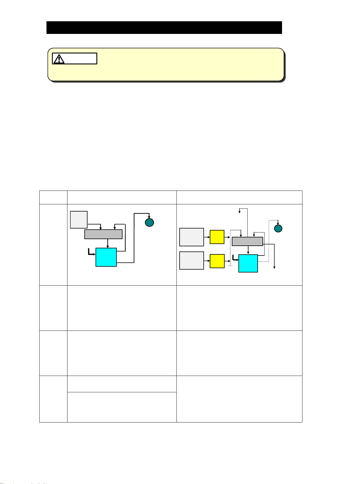
Operation
Take measures to prevent people from coming into direct contact with
product outlets. Failure to do so may result in burns or other injury from
the discharge of fluids.
CAUTION
(1) When condensate flows from the condensate inlet pipe through the inlet check valve
into the body of the unit, the air in the body escapes through the exhaust valve (which
equalizes the internal pump pressure to the pressure of the condensate source) and
the float rises, as shown in (1) below.
In the case of the GT, the main valve on the trap unit opens as the float rises.
When Pi > Pb(when the equipment pressure (Pi) is greater than the back
pressure (Pb)), the condensate passes through the outlet check valve and is
discharged through the condensate outlet pipe (normal trapping function).
When Pi Pbfor both the GP and the GT, the condensate is not discharged and
collects in the body of the unit.
(2) When the float rises to its high level, the push rod on the snap-action unit rises quickly,
simultaneously closing the exhaust valve and opening the intake (motive medium)
valve. The pressure supplied by the motive medium causes the internal pressure in
the unit to become greater than the back pressure. The inlet check valve closes and
the outlet check valve is pushed open, thus discharging the condensate in the unit
through the outlet pipe, as shown in (2) below.
(3) As a result of the condensate in the unit being discharged, the water level in the unit
drops and the float descends. When the float reaches its low level, the push rod on
the snap-action unit moves down quickly, simultaneously opening the exhaust valve
and closing the intake (motive medium) valve and the status reverts to that shown in
(1) below.
(1) Condensate Inflow (2) Condensate Discharge
Outlet Check Valve
Inlet Check Valve
Outlet Check Valve
Body
Float Trap Unit Cover
Exhaust Valve
(Open)
Intake Valve
(motive medium)
(Close)
Inlet Check
Valve Condensate
Inlet Pipe
Push
Rod Condensate
Outlet Pipe
Exhaust Valve
(Close)
Intake Valve
(motive medium)
(Open)
Condensate
Outlet Pipe
172-65318MA-06 (GP10/GT10/GP14/GT14 PowerTrap) 12 Oct 2021
6
Specifications
Install properly and DO NOT use this product outside the recommended
operating pressure, temperature and other specification ranges.
Improper use may result in such hazards as damage to the product or
malfunctions which may lead to serious accidents. Local regulations
may restrict the use of this product to below the conditions quoted.
CAUTION
Use only under conditions in which no freeze-up will occur. Freezing
may damage the product, leading to fluid discharge, which may cause
burns or other injury.
CAUTION
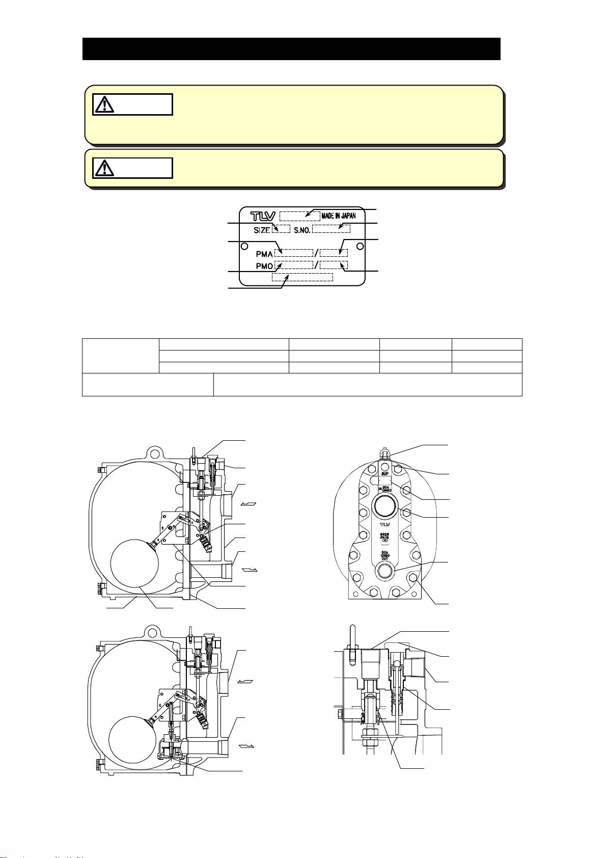
Refer to the product nameplate for detailed specifications.
* Maximum allowable pressure (PMA) and maximum allowable temperature (TMA) are
PRESSURE SHELL DESIGN CONDITIONS, NOT OPERATING CONDITIONS.
** Valve No. is displayed for products with options. This item is omitted from the nameplate when
there are no options.
Motive Medium
Pressure Range
GP10/GT10
0.03 to 1.05 MPaG
0.3 to 10.5 barg
5 to 150 psig
GP14/GT14
0.03 to 1.4 MPaG
0.3 to 14 barg
5 to 200 psig
GP14/GT14(Cast Iron in Europe)
0.03 to 1.3 MPaG
0.3 to 13 barg
5 to 185 psig
Maximum Allowable
Back Pressure
0.05 MPa/0.5 bar/7 psi less than motive medium pressure used
(but not to exceed 1.05 MPaG/10.5 barg/150 psig for the GP14/GT14)
Configuration
Model
Serial Number
Maximum Allowable
Temperature*(TMA)
Maximum Operating
Temperature (TMO)
Maximum Allowable
Pressure*
Maximum Operating
Pressure
Valve No.**
Nominal Diameter
Lever Unit
Snap-action Unit
Motive Medium Inlet
Cover
Cover GasketFloatBody
Steam Trap
Cover Bolt
Nameplate
Exhaust Outlet
Plug
Exhaust Valve Unit
GP10/GP14
GT10/GT14
Motive
Medium Inlet
Rc(PT) 1
Exhaust Outlet
Pumped
Medium
Inlet
Pumped
Medium
Outlet
Rc(PT) 1
Exhaust Outlet
Pumped Medium
Inlet
Pumped Medium
Outlet
Rc(PT) 3
Pumped Medium
Inlet
Rc(PT) 2
Pumped Medium
Outlet
Motive
Medium Inlet
Intake
Valve Unit
172-65318MA-06 (GP10/GT10/GP14/GT14 PowerTrap) 12 Oct 2021
7
Installation
Install properly and DO NOT use this product outside the recommended
operating pressure, temperature and other specification ranges.
Improper use may result in such hazards as damage to the product or
malfunctions which may lead to serious accidents. Local regulations
may restrict the use of this product to below the conditions quoted.
CAUTION
Use hoisting equipment for heavy objects (weighing approximately
20 kg (44 lb) or more). Failure to do so may result in back strain or other
injury if the object should fall.
CAUTION
Take measures to prevent people from coming into direct contact with
product outlets. Failure to do so may result in burns or other injury from
the discharge of fluids.
CAUTION
Do not use excessive force when connecting threaded pipes to the
product. Over-tightening may cause breakage leading to fluid
discharge, which may cause burns or other injury.
CAUTION
Use only under conditions in which no water hammer will occur. The
impact of water hammer may damage the product, leading to fluid
discharge, which may cause burns or other injury.
CAUTION
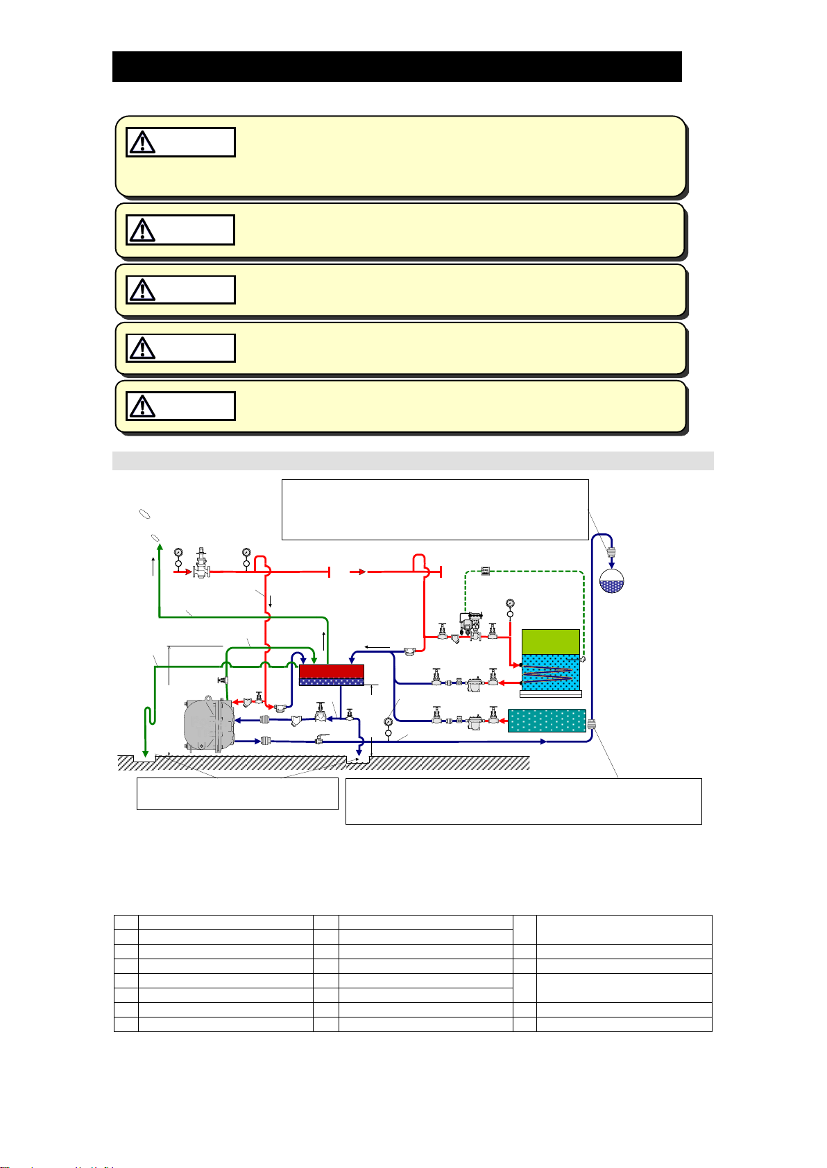
Open System Piping (Steam System Example)
NOTE: This sketch is for explanation purposes only and is not intended as an installation design.
Necessity of installing a condensate receiver
It is necessary for storing condensate during pumping.
Condensate cannot enter the PowerTrap while condensate is being pumped.
Q
Condensate Amount
Se
Exhaust Pipe
Rm
Motive Medium Pressure
Reducing Valve
A
Filling Head
Sv
Vent Pipe
Pm
Motive Medium Supply Pressure
Sf
Overflow Pipe
Pi
Equipment Pressure
Pb
Back Pressure
Dh
Condensate Receiver
St
Steam Trap on Drip leg
Si
Condensate Inlet Pipe
Ci
Condensate Inlet Check Valve
Vm
Valve on Motive Medium
Supply Pipe
So
Condensate Outlet Pipe
Co
Condensate Outlet Check Valve
Sr
Condensate Recovery Line
Ki
Condensate Inlet Strainer
Ve
Valve on Exhaust Pipe
Sm
Motive Medium Supply Pipe
Km
Motive Medium Strainer
Vb
Blowdown Valve
Ci Vo
Km
Co
Condensate
Receiver Dh
Vm
Ve
Vi
Back
Pressure
Pb Steam
Trap
Sm
Se
Si
So
Sr
Ki
Rm
St
Sv
Vb
Sf
Power
Trap Steam Trap
Steam
Trap
Temperature
Controller
Equipment
Pressure
Pi
Steam for
Heating
Vent Pipe
Steam-using
Equipment
Max. Height
3m (10 ft)
Flash Steam
Overflow
Condensate
Condensate
Recovery
Line
Backflow
Water Hammer
Prevention
Check Valve
Backflow
Water Hammer
Prevention
Check Valve
If water hammer due to steam backflow in the
condensate recovery line is expected, installation
of a check valve vertically and as close as
possible to the recovery line is recommended.
NOTE: Pipe the discharge to a
safe area such as a pit. When the rise in piping is 30 m (100 ft) or farther from the
PowerTrap, installation of a check valve is recommended
for the prevention of return water hammer.
Condensate
Amount
Q
Motive
Medium
Supply
Pressure
Pm
Primary
Pressure
for Motive
Medium
Pump
Exhaust
Other Steam-
using Equipment
Filling
Head A
172-65318MA-06 (GP10/GT10/GP14/GT14 PowerTrap) 12 Oct 2021
8
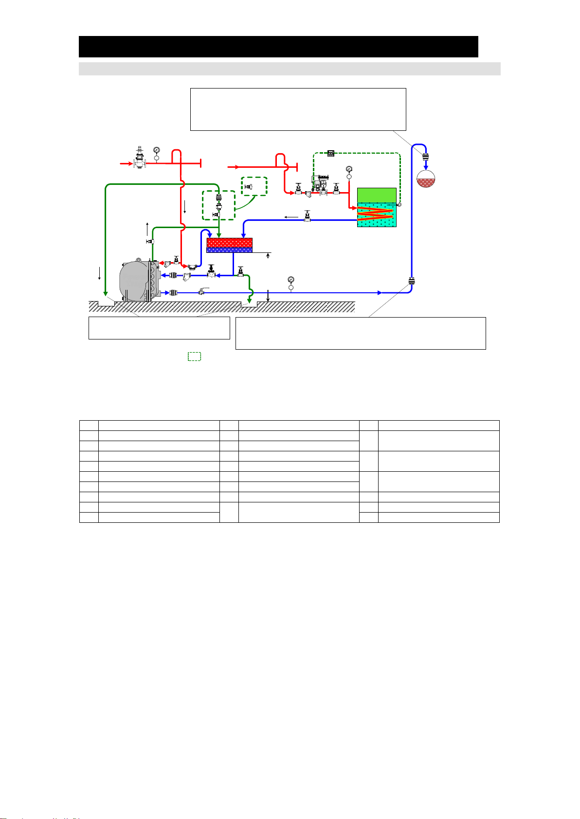
Closed System Piping (Steam System Example)
NOTE: This sketch is for explanation purposes only and is not intended as an installation design.
In closed system applications, the motive medium must be compatible with the liquid being
pumped. If a non-condensable gas such as air or nitrogen is used as the motive medium,
please consult TLV for assistance.
Q
Condensate Amount
Dh
Condensate Reservoir
St
Steam Trap on Drip Leg
A
Filling Head
Ci
Condensate Inlet Check Valve
Vi
Valve on Condensate Inlet
Pipe
Pm
Motive Medium Supply Pressure
Co
Condensate Outlet Check Valve
Pb
Back Pressure
Ca
Check Valve for Air Vent
Vo
Valve on Condensate Outlet
Pipe
Si
Condensate Inlet Pipe
La
Air Vent (for Steam)
So
Condensate Outlet Pipe
Ki
Condensate Inlet Strainer
Vm
Valve on Motive Medium
Supply Pipe
Sr
Condensate Recovery Line
Km
Motive Medium Strainer
Sm
Motive Medium Supply Pipe
Pi
Equipment Pressure
Ve
Valve on Exhaust Pipe
Se
Exhaust Pipe
Rm
Motive Medium Pressure
Reducing Valve
Va
Valve for Air/Gas Discharge
Sv
Vent Pipe
Vb
Blowdown Valve
Ci Vo
Motive
Medium
Co
Ve
Vi
Back
Pressure
Pb
Sm
Se
Si
So
Ki
Rm
Km
Vm St
Vb
Sv
La Ca Va
*Sr
Condensate
Recovery
Line
Backflow
Water Hammer
Prevention
Check Valve
Backflow
Water Hammer
Prevention
Check Valve
NOTE: Pipe the discharge to a
safe area such as a pit. When the rise in piping is 30 m (100 ft) or farther from the
PowerTrap, installation of a check valve is recommended
for the prevention of return water hammer.
Power
Trap
If water hammer due to steam backflow in the
condensate recovery line is expected, installation
of a check valve vertically and as close as
possible to the recovery line is recommended.
Motive
Medium
Supply
Pressure
Pm Temperature
Controller
Steam for
Heating
Condensate
Amount Q
Equipment
Pressure
Pi
Pump
Exhaust Condensate
Reservoir Dh
Filling
Head A
*Products shown in the are the valves, which can be replaced independently.
Steam-using
Equipment
Air and Non-condensate
Gas Discharge

172-65318MA-06 (GP10/GT10/GP14/GT14 PowerTrap) 12 Oct 2021
9
Installation Procedure
system and model (GT or GP) for the application. Installation, inspection, maintenance,
repairs, disassembly, adjustment and valve opening/closing should be carried out only by
trained maintenance personnel.
(1) Pumped Medium:
Fluids that can be discharged through the PowerTrap are limited to steam
condensate and water. PowerTraps that have been constructed for other specific
fluids are not limited by this restriction.
(2) Motive Medium Supply Piping:
The motive medium supply pipe diameter should be at least 20 mm (3/4in).
Install a 40-mesh or finer strainer on the PowerTrap motive medium supply pipe, as
close to the PowerTrap as possible, while allowing sufficient space for
positions for horizontal installations.
See the section for the maximum motive medium inlet pressure.
For Open Systems:
Steam, compressed air or nitrogen may be used as the motive medium.
For Closed Systems:
Use steam as the motive medium. Except in special cases, do no use
non-condensable gases such as air or nitrogen.
When the motive medium is steam, if the application will require that the equipment
be shut down (non-operating) for periods of 2 months or longer, install piping
connecting the motive medium supply line to the receiver/reservoir pipe, being sure
to install a drip leg on the motive medium supply line, and a steam trap in the drip leg
(between where it branches to go to the PowerTrap and where it enters the
receiver/reservoir pipe). (See item [St] in the Open/Closed system Piping drawings.)
This measure is not necessary when the motive medium is compressed air or nitrogen.
(3) Pressure Reducing Valve on the Motive Medium Supply Piping:
When the supply pressure of the motive medium is greater than the maximum
operating pressure of the PowerTrap, install a TLV COSPECT series pressure
reducing valve. Make sure that the motive medium pressure is lower than the
maximum operating pressure of the PowerTrap. Use good piping practices when
selecting the installation location for COSPECT.
In this case, be sure to install a safety valve between the pressure reducing valve
and the PowerTrap.
When the supply pressure of the motive medium is less than the maximum
operating pressure of the PowerTrap, if a pressure reducing valve is to be installed
to slow the speed of the flow, the installation of a safety valve is not required.
Install the pressure reducing valve as far away from the PowerTrap as possible.
When the motive medium pressure is less than 0.5 MPaG (72.5 psig, 5 barg): at
least 3 m (10 ft)
When the motive medium pressure is 0.5 MPaG or greater (72.5 psig or greater, 5
barg or greater): at least 3 m + 1 m for every 0.1 MPaG (1 barg) over 0.5 MPaG (5
barg) (10 ft + 1 ft for every 4.5 psig over 72.5 psig)
The pressure setting on the pressure reducing valve should be between 0.05 and
0.15 MPa (7 to 20 psi, 0.5 to 1.5 bar) higher than the back pressure.
When the discharge capacity of the PowerTrap is insufficient for the set motive
pressure, increase this set pressure even further.
172-65318MA-06 (GP10/GT10/GP14/GT14 PowerTrap) 12 Oct 2021
10
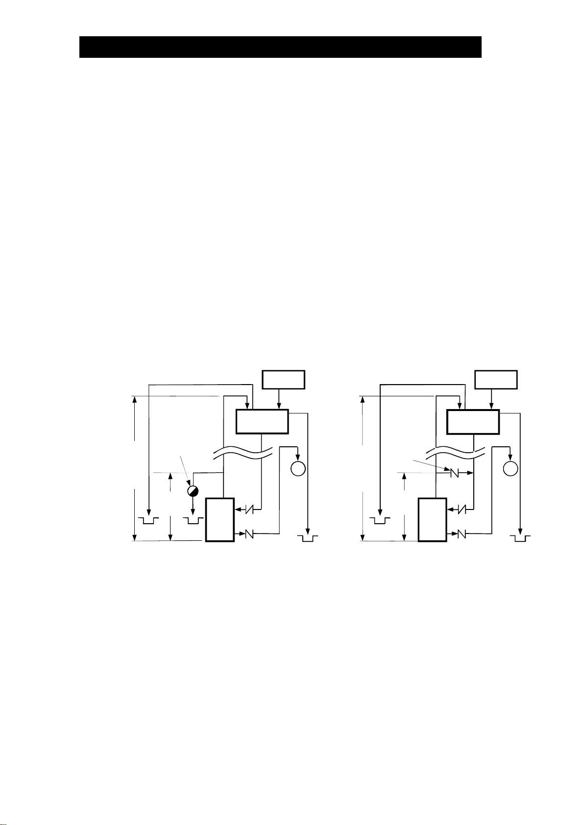
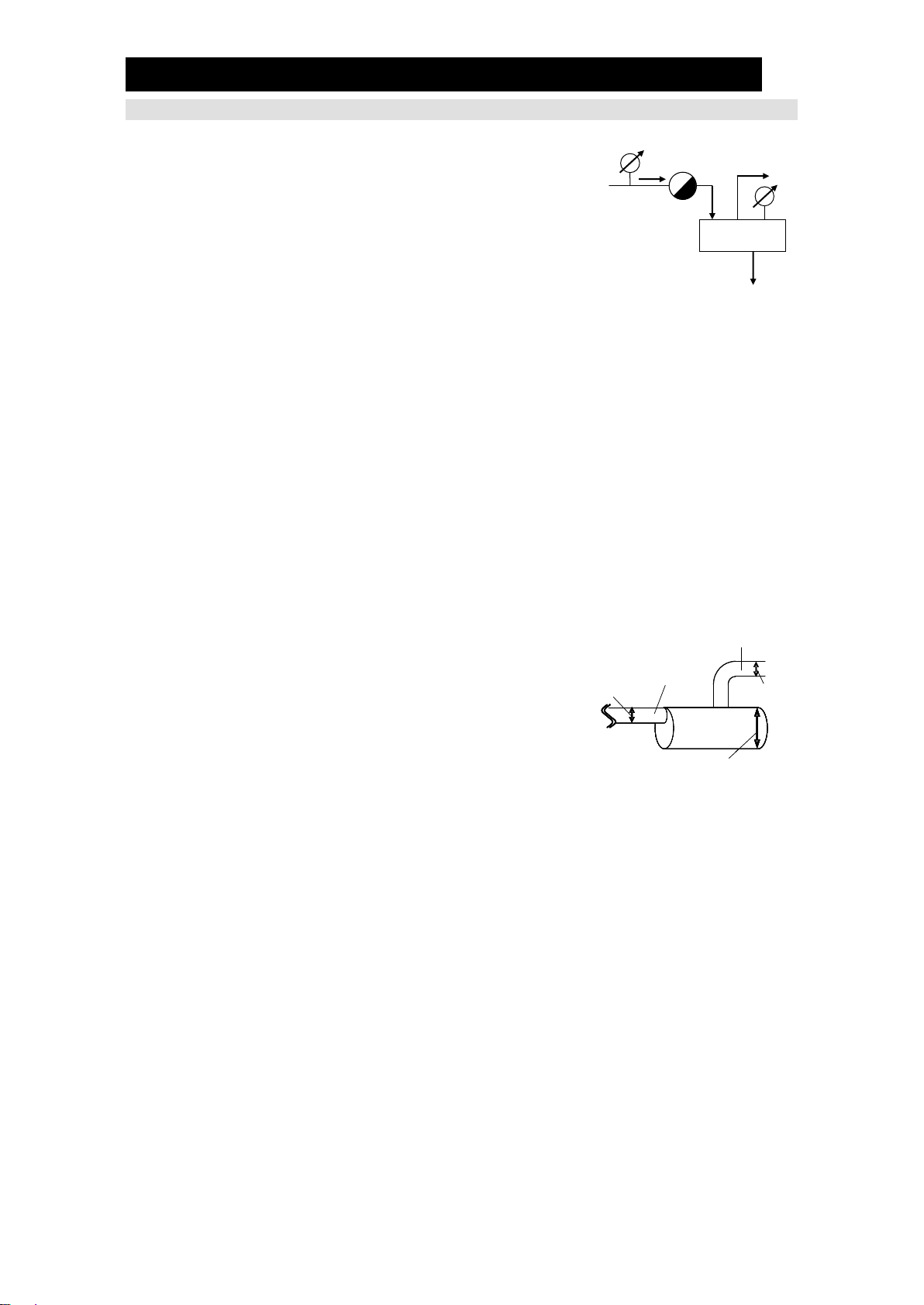
(4) Exhaust Piping:
The exhaust pipe diameter should be at least 25 mm (1 in).
The exhaust pipe should be connected to the top of the receiver/reservoir.
For Open Systems: If the GP exhaust line has to discharge to atmosphere, a
sound level of approximately 90 to 100dB (GP10) or 90 to 110dB (GP14) may be
emitted from the exhaust pipe discharge outlet for two to three seconds. If
soundproofing measures are necessary, install a silencer. (If the exhaust line is
connected to the condensate receiver, the sound level will be below 60dB.)
Make sure that the distance from the ground to the highest point on the exhaust
pipe (where it enters the receiver/reservoir) does not exceed 3 m (10 ft).
If it exceeds 3 m (10 ft) and steam is used as the motive medium, condensate must
be drained from the exhaust pipe in order not to obstruct the exhaust. Implement
one of the following countermeasures: (See the figures below.)
(a) For Open Systems only: Add a float-type steam trap to the exhaust pipe at a
point just above where the exhaust pipe exits the unit body. (Figure 1)
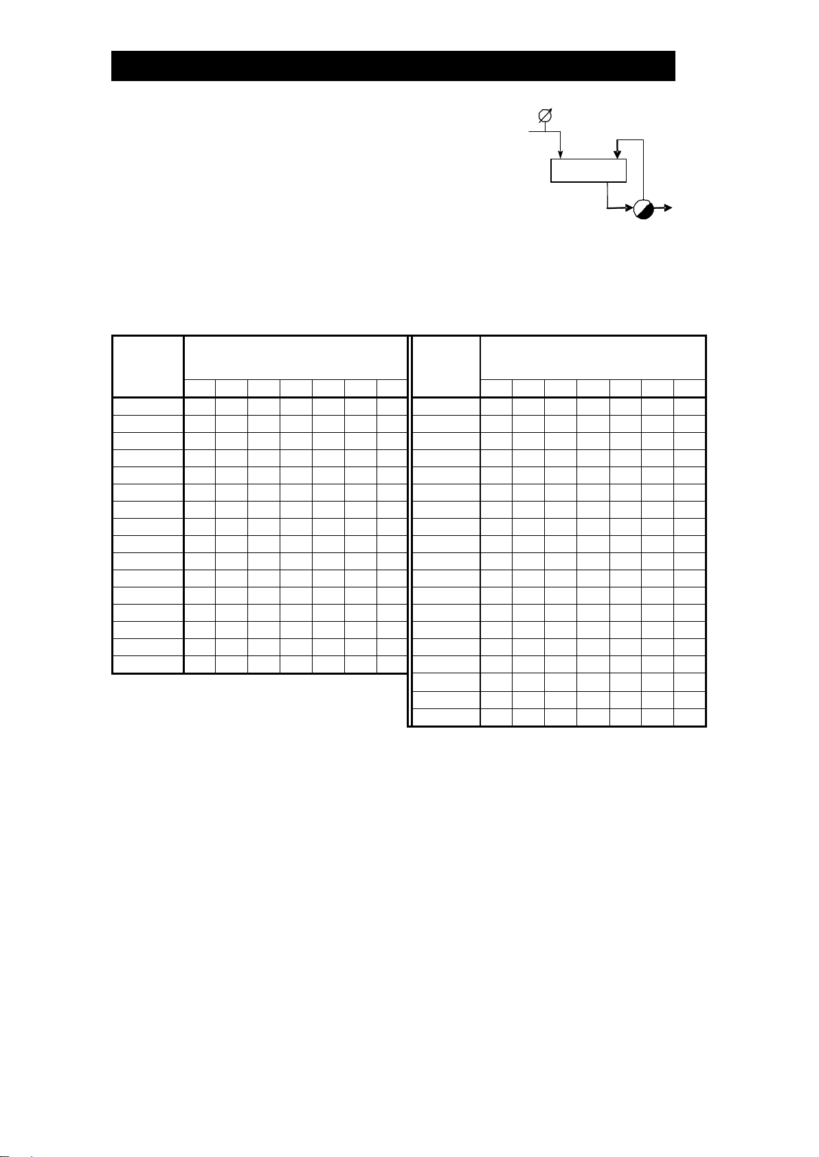
(b) For Open and Closed Systems: Add piping connecting the exhaust pipe to
the pumped medium inlet pipe between the reservoir and the strainer, being
sure to install a check valve on the piping to prevent backflow of condensate
from the pumped medium inlet pipe to the exhaust pipe. (Figure 2)
For Closed Systems only: The exhaust pipe must be connected to the top of the
reservoir.
(5) Inlet and Outlet Piping
Install a 40-mesh or finer strainer on the PowerTrap pumped medium inlet pipe.
The installation should be in a location that allows sufficient space for maintenance
of the strainer.
Ensure that the inlet and outlet check valves are installed in the correct direction.
The check valve on the inlet pipe in particular should be installed right next to the
PowerTrap.
Only TLV check valves (CK3MG, CKF3MG) should be used; proper discharge
capacity cannot be guaranteed with other check valves.
Equipmen
t
Power
Trap
Power
Trap
Power
Trap
Power
Trap
When the exhaust piping height exceeds 3 m (10 ft.)
Figure 1: Open Systems Figure 2: Open & Closed Systems
* For Open Systems only
Vent Line*
Vent Line Equipment
Pit
Close to
Pit
Pit
Receiver
Pit
Close to
Equipment
Steam
Trap
When the
exhaust
piping is
3 m (10 ft.)
or more
When the
exhaust
piping is
3 m (10 ft.)
or more
Exhaust
Piping
Inlet
Pipe
Outlet
Pipe
Exhaust
Piping
Inlet
Pipe
Outlet
Pipe
Check
Valve
Overflow
Pipe*
Receiver/
Reservoir
Pit
Overflow
Pipe*

172-65318MA-06 (GP10/GT10/GP14/GT14 PowerTrap) 12 Oct 2021
11
(6) Valves on the Various Pipes
In order to ensure the proper discharge capacity, use full bore ball valves or gate
valves on the pumped medium inlet and outlet lines as well as on the motive
medium supply and exhaust lines.
If it is necessary to reduce the velocity of the motive medium supply, a needle valve
can be used. However, be aware that the discharge capacity will be reduced.
(1). e).)
Install union or flanged joints between the valves and the PowerTrap to allow for
easy maintenance.
Be sure to provide the necessary maintenance space for PowerTrap disassembly
and repair (see the section).
(7) Receiver/Reservoir Pipe and Filling Head
Please refer to the ing the Condensate section.
The size and vent pipe aperture are determined by (a) the amount of any flash
steam in the in-flowing condensate (pumped medium) and (b) the amount of
pumped medium held back while the PowerTrap is discharging.
If the receiver is small, the flow of flash steam may cause condensate to flow out
the vent pipe.
If the vent pipe size is small, the pressure in the receiver will rise, restricting the
pumped medium inflow.
Be sure to select a receiver/reservoir pipe of the correct size.
The filling head represents the distance from the bottom of the PowerTrap (from
grade) to the bottom of the receiver/reservoir.
The standard filling head is 860 mm (36 in).
When an installation calls for a lower filling head, a filling head of less than 860 mm
(36 in) is allowable. However, the minimum filling head is 710 mm (30 in).
For Open Systems:
- If venting flash steam to a high area, an overflow pipe must be installed to discharge
condensate to a safe area.
- Overflow pipe should be installed at the side of the receiver.
Be sure to install a vent pipe and an overflow pipe. Failure to install an
overflow pipe is dangerous, as condensate may spurt from the vent pipe
and could result in burns and other injuries.
Pipe the vent pipe and the overflow pipe to a safe place such as a pit.
Piping size of the overflow pipe should be the same or larger than
condensate inlet pipe.
WARNING
Examples of Overflow Piping for Open Systems
300 mm
(12 in)
Condensate
Receiver
1) 2) Flash Steam
Flash Steam
Condensate
Receiver
To PowerTrap
To PowerTrap
Flash Steam
Vent Pipe Vent Pipe
Overflow Pipe Overflow Pipe
Condensate
Condensate
Loop Seal
NOTE:
This sketch is for
explanation purposes only
and is not intended as an
installation design.
Pipe the discharge to a safe place such as a pit.
High temperature steam or hot water may splash.
There is a possibility of condensed hot water dripping from vent pipe outlet.
Make sure to extend to where people do not pass.

172-65318MA-06 (GP10/GT10/GP14/GT14 PowerTrap) 12 Oct 2021
12
Explanations for Overflow Piping for Open Systems
1) If flash steam can be discharged from overflow pipe
Install overflow pipe and vent pipe separately.
2)
If flash steam should not be released from overflow pipe (prevent flash steam release)
Install overflow pipe and vent pipe separately. For overflow pipe, install loop
seal (approx. 300 mm (12 in)). Flash steam release from overflow pipe can be
prevented since water always accumulates at loop seal. Piping size should be
the same or larger than condensate supply pipe.
water always present in the loop seal. The possibility is greater if the
piping diameter is too small (generally 25 mm (1 in) or smaller).
pipe. Make sure to install vent pipe to lead to a safe place
Do not install loop seal on the vent pipe
Contact TLV if neither 1) nor 2) above can be installed.
(8) Velocity at Outlet Piping
The PowerTrap uses the motive medium supply pressure to push the pumped
medium out of the trap.
The GP10/GT10/GP14/GT14 can discharge approximately 30 liters (8 U.S. gal) of
pumped medium for each discharge operation.
The amount of time required for each discharge operation will be between 3 and 30
seconds, depending on the back pressure and the motive medium pressure.
This means that the instantaneous flow through the pumped medium outlet pipe
during the discharge operation is between 4 and 40 metric tonnes (1,060 and
10,600 U.S. gal) per hour.
When a flowmeter is to be installed in the pumped medium outlet piping, it should
be selected to reflect the intermittent operation and should be sized to
accommodate the maximum and minimum instantaneous flow. Contact TLV for
details.
(9) For Closed Systems:
An air vent (for steam) [La] or valve for air discharge [Va] is required to discharge
the initial air in the equipment and the reservoir pipe or any gas generated in the
system. In this case, installing the check valve for air vent [Ca] will prevent air from
being sucked in from the outlet of the vent pipe [Sv]. This check valve must be
installed when the pressure inside the piping becomes negative. A valve for air
discharge [Va] can be installed instead of the air vent (for steam) [La] and check
valve for air vent [Ca].
When releasing the initial air using a valve for air discharge, leave the valve for air
discharge [Va] slightly open until the PowerTrap has cycled 2 3 times. Close the
valve for normal operation.
Select the appropriate PowerTrap model (GT or GP) based on the explanation in
General Description.
Refer to (2) When flash steam is not involvedin Sizing the Condensate Receiver/
Reservoirfor information on condensate reservoir sizing.
For more details, contact TLV.
172-65318MA-06 (GP10/GT10/GP14/GT14 PowerTrap) 12 Oct 2021
13
Sizing the Condensate Receiver/Reservoir
When selecting the receiver/reservoir for the
PowerTrap, select from among the following 3 conditions:
(1) When large quantities of flash steam are involved
(For open systems using steam)
a) Determine the amount of flash steam:
Amount of flash steam Fs = Q
Fs : amount of flash steam (kg/h) (lb/h)
Q : amount of condensate (kg/h) (lb/h)
: specific enthalpy (kJ/kg) (Btu/lb) of saturated condensate at
condensate inlet set pressure (Pi)
: specific enthalpy (kJ/kg) (Btu/lb) of saturated condensate at
condensate receiver set pressure (Ph)
r : specific enthalpy (kJ/kg) (Btu/lb) vaporization (latent heat of
steam) at condensate receiver set pressure (Ph)
b) Determine the vent pipe diameter according to the amount of flash steam in
Vented Receiver Table - 1 shown on the next page.
c) Determine the overflow pipe diameter (Dop, refer to the figure below).
NOTE: The overflow pipe diameter should be at least as large as the condensate
inlet pipe diameter (Dcip, refer to the figure below).
d) Determine the minimum condensate receiver diameter (Dcr, refer to the figure
below) by selecting the largest value among those
from (i), (ii), and (iii) based on a condensate receiver
length of 1 m (3.3 ft).
(i) is the overflow pipe diameter multiplied by 3 or
more.
(ii) is the minimum receiver diameter according to
the amount of flash steam in Vented Receiver Table
- 1 shown on the next page.
(iii) is the minimum receiver diameter according to
the amount of condensate in Vented Receiver Table
- 2 shown on the next page.
NOTE: Receiver length can be reduced by 50% when the motive pressure (Pm)
divided by the back pressure (Pb) is "2" or greater.
(When PmPb2)
ドレンヘッダー
Dop
Overflow
Pipe
Condensate
Receiver
Condensate
Inlet Pipe
Dcr 3 Dop
Dcr
Dcip
Dop Dcip
Receiver
Pi
Ph
Flash Steam
Condensate
Qi

172-65318MA-06 (GP10/GT10/GP14/GT14 PowerTrap) 12 Oct 2021
14
Vented Receiver Table - 1
(For atmospheric, open system installations, applicable trap –GP10/GP14)
Flash Steam
up to ~
kg/h
Receiver Diameter
mm (in)
(Length: 1 m)
Vent Line
Diameter
mm (in)
Flash Steam
up to ~
lb/h
Receiver Diameter
in
(Length: 3.5 ft)
Vent Line
Diameter
in
25
80
(3)
25
(1)
50
3
1
50
100
(4)
50
(2)
75
4
11/2
75
125
(5)
50
(2)
100
4
2
100
150
(6)
80
(3)
200
6
21/2
150
200
(8)
80
(3)
300
8
3
200
200
(8)
100
(4)
400
8
4
300
250
(10)
125
(5)
600
10
4
400
300
(12)
125
(5)
800
12
6
500
350
(14)
150
(6)
1000
14
6
700
400
(16)
200
(8)
1400
16
8
800
450
(18)
200
(8)
1600
18
8
1000
500
(20)
200
(8)
2000
20
8
1100
500
(20)
250
(10)
2200
20
10
1400
550
(22)
250
(10)
2800
22
10
1500
600
(24)
250
(10)
3000
24
10
Vented Receiver Table - 2
(For atmospheric, open system installations, applicable trap –GP10/GP14)
Amount of
Condensate
kg/h
Receiver Diameter
mm (in)
(Length: 1 m)
Amount of
Condensate
lb/h
Receiver Diameter
in
(Length: 3.5 ft)
1000 or less
80
(3)
2200 or less
3
1500
100
(4)
3300
4
2000
125
(5)
4400
5
3000
150
(6)
6600
6
6000
200
(8)
13000
8
10000
250
(10)
22000
10
NOTE: When amount of flash steam and condensate are between two values in the table, select
the larger value (one line below).
172-65318MA-06 (GP10/GT10/GP14/GT14 PowerTrap) 12 Oct 2021
15
(2) When flash steam is not involved
(For closed systems)
Determining the reservoir diameter and
length based on the amount of condensate:
Reservoir Table
(For equalized, closed system installations)
Amount of
Pumped
Medium
Reservoir Diameter (mm) & Length (m)
Amount of
Pumped
Medium
Reservoir Diameter (in) & Length (ft)
(kg/h)
40
50
80
100
150
200
250
(lb/h)
1½
2
3
4
6
8
10
300 or less
1.2m
0.7
500 or less
3.0 ft
2.0
400
1.5
1.0
700
4.0
2.5
1.0
500
2.0
1.2
0.5
1000
5.5
3.5
1.5
600
1.5
0.6
1200
4.5
2.0
1.0
800
2.0
0.8
0.5
1500
2.5
1.5
1000
1.0
0.7
2000
3.5
2.0
1500
1.5
1.0
3000
4.5
3.0
2000
2.0
1.3
0.6
4000
6.5
4.0
1.5
3000
2.0
0.9
0.5
5000
5.0
2.5
4000
1.2
0.7
6000
5.5
2.5
1.5
5000
1.4
0.8
0.5
7000
6.5
3.0
1.5
6000
1.7
1.0
0.6
8000
3.5
2.0
7000
2.0
1.2
0.7
9000
4.0
2.5
1.5
8000
1.3
0.8
10000
4.5
2.5
1.5
9000
1.5
0.9
12000
5.0
3.0
2.0
10000
1.7
1.0
14000
6.0
3.5
2.5
16000
6.5
4.0
2.5
18000
4.5
3.0
20000
1.5
1.5
NOTE: Reservoir length can be reduced by 50% when the motive pressure (Pm) divided by the
back pressure (Pb) is "2" or greater. (When Pm ÷ Pb2)
(3) When there are small quantities of flash steam and a large amount of condensate
(e.g., open systems pumping large amounts of super-cooled condensate)
Consult the sizing tables in sections (1) and (2).
Select the condensate receiver size based on the larger of (1) and (2).
Select the vent pipe diameter and overflow pipe diameter from (1).
Reservoir
Pi
Condensate
PowerTrap

172-65318MA-06 (GP10/GT10/GP14/GT14 PowerTrap) 12 Oct 2021
16
Installing Several PowerTrap Units in Parallel
Refer to the figure below as a general guide for the piping when several PowerTrap units
are to be installed after the same pumped medium inlet pipe.
The size of the pumped medium inlet pipe, return line and exhaust pipe manifold is
determined by the number of PowerTrap units installed.
When specifications exist separately from the instruction manual, follow the
specifications.
NOTE: This sketch is for explanation purposes only and is not intended as an installation design.
Number of
PowerTrap
Units Installed
Pumped Medium
Inlet Pipe Size
Pumped
Medium Return
Line Size
Exhaust Pipe
Manifold Size
Overflow Pipe
Size
Vent Pipe Size
2
125 mm (5 in)
80 mm (3 in)
40 mm (11/2in)
Determine
overflow pipe size
according to
Sizing the
Condensate
Receiver/
Reservoir
See the Vent
Line Diameter
column in
Table-1 in
Sizing the
Condensate
Receiver/
Reservoir
3
150 mm (6 in)
100 mm (4 in)
50 mm (2 in)
4
200 mm (8 in)
100 mm (4 in)
65 mm (21/2in)
5
200 mm (8 in)
125 mm (5 in)
65 mm (21/2in)
6
200 mm (8 in)
125 mm (5 in)
80 mm (3 in)
Pumped Medium Return Line
Pumped Medium Inlet Pipe
Pumped Medium
Exhaust Pipe
Filling Head A
Motive
Medium
Supply
Overflow Pipe
Receiver
Medium Return
(Main Line)
Vent Pipe
Exhaust Pipe Manifold
TLV
Power
Trap
Exhaust Pipe
Exhaust Pipe
Motive
Medium
Supply
Motive
Medium
Supply
TLV
Power
Trap
TLV
Power
Trap
172-65318MA-06 (GP10/GT10/GP14/GT14 PowerTrap) 12 Oct 2021
17
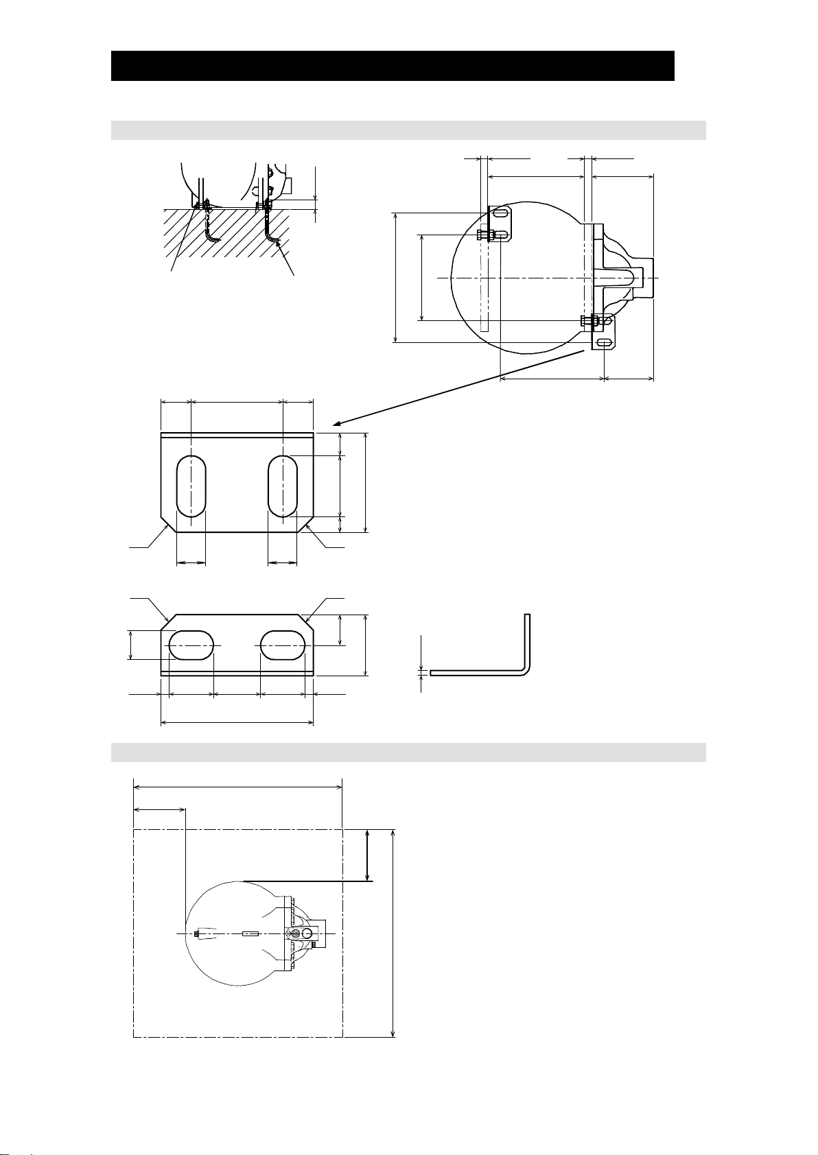
Installation and Maintenance Space
Anchoring the Body
Maintenance Space
The maintenance space shown in the
figure on the left should be provided to
enable disassembly/reassembly,
inspection and replacement of the
PowerTrap.
Maintenance may not be performed if
there is not enough space.
Unit: mm (in)
40
(1)
PowerTrap
(Customer Supplied)
Hex Bolt with Nut
M16 × 50 mm, 2 pcs.
(Included with
Anchor Fixture Set)
11UNC ×1in)
Anchor Bolt with nut
M16, 2 pcs.
1
~268 173
360
240
290 138
20
60
20
10
40
15
65
C10C10
19
19
C10 C10
5.5
29
31
29
5.5
100
19
20
40
20
Anchor Fixture Set included in the package.
Fixture is designed so that the body can be moved
backwards (opposite direction to the cover).
Failure to use fixtures or use of other than those
provided may prevent mobility of the body, and
inhibit maintenance.
(Consisting of two anchor brackets and two hex
bolts with nuts)
(Suitable Anchor Bolt Size: M16)
(Bolt Holes in Product Body: ø19)
Anchor fixture set:
Anchor fixture × 2
Hex bolt (M16) × 2
Hex nut (M16) × 2
Washer (Diameter: 16) × 2
Unit: mm (in)
3.2
Maintenance Space
Approx. 2000
Approx. 2000
800
800

172-65318MA-06 (GP10/GT10/GP14/GT14 PowerTrap) 12 Oct 2021
18
Operation and Periodic Inspection
After all piping work has been completed in accordance with the
specific piping system designed when the decision to utilize the
PowerTrap was made, check once again to make sure that all pipe
connections have been tightened, gaskets have been inserted where
needed and all parts are securely installed.
When beginning operation, make sure that the operator stays well clear
of the release area of the vent line and overflow piping.
At the start-up of operation, large quantities of condensate may flow,
causing the PowerTrap to momentarily overload. If this occurs in open
systems, hot condensate may spurt from the vent piping or overflow
piping and could result in burns, other injuries or damage to equipment.
WARNING
・Repairs or disassembly of the piping, adjustment and valve opening/
closing should be carried out only by trained maintenance personnel.
・Before connecting piping or disassembling the product, close the inlet
and outlet valves and make every effort to reduce the internal pressure
to cool the product to room temperature.
・When disassembling connecting parts, remove pipes and bolts slowly to
prevent condensate from suddenly flowing out in the event of residual
pressure inside the product.
CAUTION
Install properly and DO NOT use this product outside the recommended
operating pressure, temperature and other specification ranges.
Improper use may result in such hazards as damage to the product or
malfunctions which may lead to serious accidents. Local regulations
may restrict the use of this product to below the conditions quoted.
CAUTION
When disassembling or removing the product, wait until the internal
pressure equals atmospheric pressure and the surface of the product
has cooled to room temperature. Disassembling or removing the
product when it is hot or under pressure may lead to discharge of fluids,
causing burns, other injuries or damage.
CAUTION
Be sure to use only the recommended components when repairing the
product, and NEVER attempt to modify the product in any way. Failure to
observe these precautions may result in damage to the product or burns
or other injury due to malfunction or the discharge of fluids.
CAUTION
Installation, inspection, maintenance, repairs, disassembly, adjustment and valve
opening/closing should be carried out only by trained maintenance personnel.
Operation
(1) Valve Operation
Refer to the drawi
various valves.
If water hammer has occurred, immediately cease operation and close any valves
that are operating.
a) Slowly open the valve [Ve] on the exhaust pipe.
b) Slowly open the valve [Vm] on the motive medium supply pipe.
Make sure that there is no sound of flow from the exhaust pipe [Se] or the
pumped medium inlet pipe [Si].
c) Slowly open the valve [Vo] on the pumped medium outlet pipe.
d) Slowly open the valve [Vi] on the pumped medium inlet pipe.
When using a valve for air/gas discharge [Va] for venting air on a closed system,
leave the valve [Va] slightly open until the PowerTrap has cycled 2 or 3 times in
order to release any air inside the system, then close the valve [Va].

172-65318MA-06 (GP10/GT10/GP14/GT14 PowerTrap) 12 Oct 2021
19
e) The PowerTrap is normal if it operates intermittently; first exhausting the motive
medium to fill with pumped medium, then taking in motive medium to force the
pumped medium out.
The interval of operation will vary greatly depending on the amount of pumped
medium inflow, the temperature, the motive medium (steam or gas) and the
motive pressure. (The interval of operation is considered to be the length of time
between the start of one discharge cycle and the start of the next discharge
cycle.)
The interval of operation Tc (s) can be roughly determined using the following
formula:
Tc=108,000/Q or Tc=238,000/Qp
Q: amount of condensate (inflowing pumped medium) (kg/h)
Qp: amount of condensate (inflowing pumped medium) (lb/h)
The GP10/GT10/GP14/GT14 can discharge approximately 30 liters (8 U.S. gal)
of pumped medium for each discharge operation.
The amount of time required for each discharge operation will be between 3 and
30 seconds, depending on the back pressure and the motive medium pressure.
(2) If an error such as a leak or water hammer occurs after beginning PowerTrap
operation, shut off the valves immediately in the following order:
valve [Vm] on motive medium supply pipe pumped medium inlet valve [Vi]
pumped medium outlet valve [Vo] valve [Ve] on exhaust pipe
(3) Whenever any type of malfunction is suspected in the PowerTrap, refer to the
Periodic Inspection and Diagnosis
There are two types of periodic inspection: the visual inspection and the disassembly
inspection.
(1) Visual Inspection
As a general rule, this inspection should be performed at least once every 3 months.
Check the following items:
a) There should be no leakage from the PowerTrap or from any of the connections.
b) The PowerTrap unit should be operating cyclically (one indication being the
sharp, mechanical sound of the snap-unit operating at the transition between the
filling and the discharge parts of the cycle). Immediately after the end of the
discharge part of the cycle and during the filling part of the cycle, the sound of
flow in the exhaust pipe should be heard. During the pumping (discharge) part of
the cycle, flow in the motive medium supply pipe should be heard.
c) Pumped medium should not accumulate in the (steam-using) equipment, and
the temperature of the equipment should not be abnormally low.
d) For open systems, verify that an overflow pipe from the receiver is installed.
e) For open systems, no steam should be seen flowing out through the vent pipe.
f) There should not be any abnormal noise from the pumped medium outlet pipe or
the pumped medium recovery line when the PowerTrap operates.
This manual suits for next models
11
Table of contents
Other TLV Water Pump manuals


Popular Water Pump manuals by other brands

Graco
Graco SaniForce 1590 HS Instructions-parts list

Pratissoli
Pratissoli MW Series Use and maintenance manual

Ingersoll-Rand
Ingersoll-Rand ARO PD10P Series Operator's manual

Kärcher
Kärcher BPE 4200/50 instructions

Alemlube
Alemlube O30060 instruction manual

Wilo
Wilo DrainLift M2/8 Installation and operating instructions


