TLV PowerTrap GP10L-1AJ User manual
172-65510MA-05 (GP Series System Package) 27 December 2016
System Package
GP10L-1AJ
GP14L-1AJ
GP14M-1BJ
GP10-1CJ
GP10-2FJ
Copyright © 2016 by TLV CO., LTD.
All rights reserved

172-65510MA-05 (GP Series System Package) 27 Dec 2016
1
Contents
Introduction.......................................................................1
Safety Considerations.......................................................2
General Description..........................................................4
Specifications....................................................................5
Configuration.....................................................................6
Installation.........................................................................8
Installation and Maintenance Space...............................13
Operation and Periodic Inspection..................................15
Product Warranty............................................................18
Introduction
Thank you for purchasing the PowerTrap system package (hereinafter
referred to as "system package").
This product has been thoroughly inspected before being shipped from the factory.
When the product is delivered, before doing anything else, check the specifications
and external appearance to make sure nothing is out of the ordinary. Also be sure to
read this manual carefully before use and follow the instructions to be sure of using
the product properly.
This instruction manual only describes contents regarding installation of the system
package. Detailed instructions for PowerTrap unit(s) included in this system
package are not described. Please refer to the instruction manual(s) for each
PowerTrap unit.
If detailed instructions for special order specifications or options not contained in this
manual are required, please contact for full details.
This instruction manual is intended for use with the model(s) listed on the front cover.
It is necessary not only for installation, but for subsequent maintenance and
relocating the system package. Please keep it in a safe place for future reference.
The contents of this manual are subject to change without notice.
172-65510MA-05 (GP Series System Package) 27 Dec 2016
2
Safety Considerations
•Read this section carefully before use and be sure to follow the instructions.
•This instruction manual only describes contents regarding installation of the
system package. Detailed instructions for PowerTrap unit(s) included in this
system package are not described. Please refer to the instruction manual(s) for
each PowerTrap unit.
•Installation, inspection, maintenance, repairs, disassembly, adjustment and valve
opening/closing should be carried out only by trained maintenance personnel.
•The precautions listed in this manual are designed to ensure safety and prevent
equipment damage and personal injury. For situations that may occur as a result
of erroneous handling, three different types of cautionary items are used to
indicate the degree of urgency and the scale of potential damage and danger:
DANGER, WARNING and CAUTION.
•The three types of cautionary items above are very important for safety: be sure
to observe all of them as they relate to installation, use, maintenance and repair.
Furthermore, TLV accepts no responsibility for any accidents or damage
occurring as a result of failure to observe these precautions.
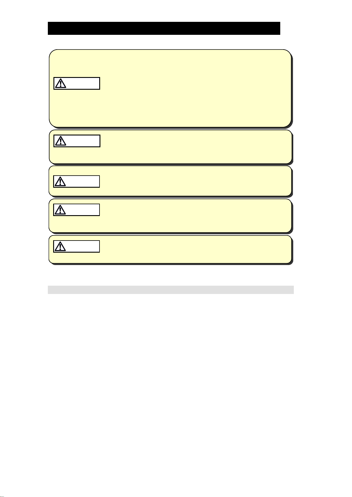
Symbols
Indicates a DANGER, WARNING or CAUTION item.
DANGER
Indicates an urgent situation which poses a threat of death or
serious injury
WARNING
Indicates that there is a potential threat of death or serious injury
CAUTION
Indicates that there is a possibility of injury or equipment / product
damage
CAUTION
Install properly and DO NOT use this product outside the
recommended operating pressure, temperature and other
specification ranges.
Improper use may result in such hazards as damage to the
product or malfunctions that may lead to serious accidents. Local
regulations may restrict the use of this product to below the
conditions quoted.
Use hoisting equipment for heavy objects (weighing
approximately 20 kg (44 lb) or more).
Failure to do so may result in back strain or other injury if the
object should fall.
Take measures to prevent people from coming into direct
contact with product outlets.
Failure to do so may result in burns or other injury from the
discharge of fluids.
When disassembling or removing the product, wait until the
internal pressure equals atmospheric pressure and the
surface of the product has cooled to room temperature.
Disassembling or removing the product when it is hot or under
pressure may lead to discharge of fluids, causing burns, other
injuries or damage.
Safety considerations are continued on the next page.
172-65510MA-05 (GP Series System Package) 27 Dec 2016
3
CAUTION
Be sure to use only the recommended components when
repairing the product, and NEVER attempt to modify the
product in any way.
Failure to observe these precautions may result in damage to the
product and burns or other injury due to malfunction or the
discharge of fluids.
Do not use excessive force when connecting threaded pipes
to the product.
Over-tightening may cause breakage leading to fluid discharge,
which may cause burns or other injury.
Use only under conditions in which no freeze-up will occur.
Freezing may damage the product, leading to fluid discharge,
which may cause burns or other injury.
Use only under conditions in which no water hammer will
occur.
The impact of water hammer may damage the product, leading to
fluid discharge, which may cause burns or other injury.

172-65510MA-05 (GP Series System Package) 27 Dec 2016
4
General Description
Install properly and DO NOT use this product outside the recommended
operating pressure, temperature and other specification ranges.
Improper use may result in such hazards as damage to the product or
malfunctions which may lead to serious accidents. Local regulations
may restrict the use of this product to below the conditions quoted.
CAUTION
Application
The PowerTrap is a non-electric mechanical pump used to discharge high-temperature
liquid from vacuum-pressure or low-pressure areas to high-pressure areas, or from lower
to higher elevations.
This system package is pre-assembled with all the necessary devices and pipes to
operate the PowerTrap, greatly reducing labor required for installation, pipings, and
maintenance.
The discharge capacity differs depending on the system package model. Check the
latest product information to make sure the system package model you purchased is
suitable for use on the application it is planned to be used on.
For the latest product information, please contact TLV.

172-65510MA-05 (GP Series System Package) 27 Dec 2016
5
Specifications
Install properly and DO NOT use this product outside the recommended
operating pressure, temperature and other specification ranges.
Improper use may result in such hazards as damage to the product or
malfunctions which may lead to serious accidents. Local regulations
may restrict the use of this product to below the conditions quoted.
CAUTION
Use only under conditions in which no freeze-up will occur. Freezing
may damage the product, leading to fluid discharge, which may cause
burns or other injury.
CAUTION
(1) The system package model is indicated on the nameplate located on the
condensate receiver.
Please check the latest product information for the specifications of each model.
For the latest product information, please contact TLV.
Model
Serial Number
(2) For the model name of the PowerTrap unit(s), refer to the nameplate located on
the PowerTrap unit(s).
Please check the latest product information for the specifications of the
PowerTrap unit(s).
For the latest product information, please contact TLV.
Model
Serial Number
Maximum Allowable
Temperature*(TMA)
Maximum Operating
Temperature (TMO)
Maximum Allowable
Pressure*
Maximum Operating
Pressure
Valve No.**
Nominal Diameter
* Maximum allowable pressure (PMA) and maximum allowable temperature (TMA) are
PRESSURE SHELL DESIGN CONDITIONS, NOT OPERATING CONDITIONS.
** Valve No. is displayed for products with options. This item is omitted from the nameplate
when there are no options.
172-65510MA-05 (GP Series System Package) 27 Dec 2016
6
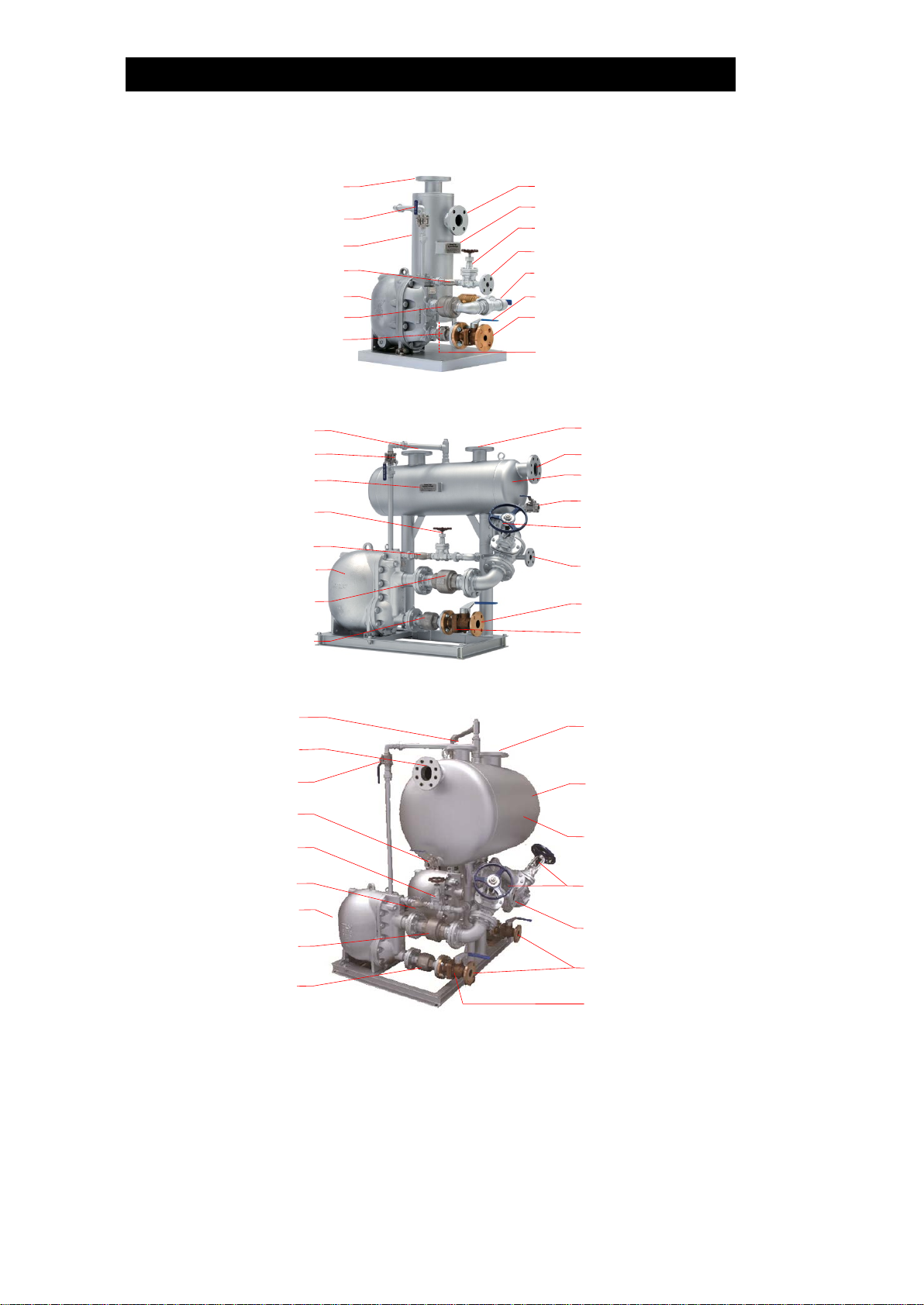
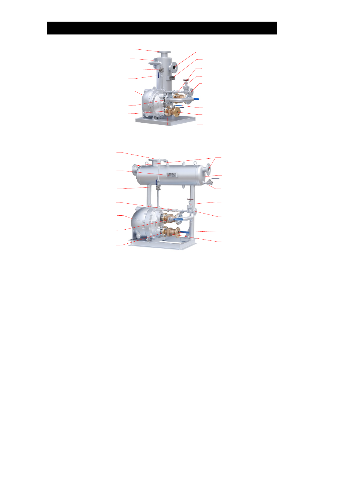
Configuration
GP10L-1AJ
Condensate Inlet
Nameplate
Motive Medium Supply Valve
Motive Medium Supply Connection
Condensate Inlet Valve
Condensate Outlet
Condensate Outlet Valve
Blow Valve
(bottom of the condensate receiver)
Vent Pipe and
Overflow Connection
Exhaust Valve
Condensate Receiver*
Motive Medium Strainer
PowerTrap
Condensate Inlet Check Valve
Condensate Outlet Check Valve
GP10-1CJ
Overflow Connection
Condensate Receiver*
Condensate Inlet Valve
Motive Medium
Supply Connection
Condensate Outlet
Condensate Outlet Valve
Blow Valve
Vent Pipe Connection
Exhaust Valve
Nameplate
Motive Medium
Supply Valve
PowerTrap
Condensate Inlet
Check Valve
Condensate Outlet
Check Valve
Motive Medium Strainer
Condensate Inlet
GP10-2FJ
Vent Pipe Connection
Condensate Receiver*
Condensate Inlet Valve
Motive Medium
Supply Connection
Condensate Outlet
Condensate Outlet Valve
Blow Valve
Condensate Inlet
Exhaust Valve Nameplate
(side of the condensate
receiver)
Motive Medium
Supply Valve
PowerTrap
Condensate Inlet
Check Valve
Condensate Outlet
Check Valve
Motive Medium Strainer
Overflow Connection
* Condensate receiver may be referred to as condensate tank or condensate header.
172-65510MA-05 (GP Series System Package) 27 Dec 2016
7
GP14L-1AJ
Condensate Inlet
Nameplate
Motive Medium Supply Valve
Motive Medium Strainer
Condensate Inlet Valve
Condensate Outlet
Condensate Outlet Valve
Vent Pipe Connection
Exhaust Valve
Condensate Receiver*
PowerTrap
Condensate Inlet Check Valve
Condensate Outlet Check Valve
Motive Medium
Supply Connection
Overflow Connection
Blow Valve
(bottom of the condensate receiver)
GP14M-1BJ
Condensate Inlet or
Overflow Connection**
Condensate Receiver*
Motive Medium
Supply Valve
Motive Medium
Supply Connection
Condensate Outlet
Condensate Outlet Valve
Blow Valve
Vent Pipe Connection
Exhaust Valve
Nameplate
PowerTrap
Condensate Inlet
Check Valve
Condensate Outlet
Check Valve
Motive Medium Strainer
* Condensate receiver may be referred to as condensate tank or condensate header.
** One connection should be used for the condensate inlet pipe, the other one should be
connected to the overflow pipe.

172-65510MA-05 (GP Series System Package) 27 Dec 2016
8
Installation
Be sure to install an overflow pipe and discharge to a safe area such as a
pit. Failure to install an overflow pipe is dangerous, as condensate may
spurt from the vent pipe and could result in burns and other injuries.
WARNING
Install properly an DO NOT use this product outside the recommended
operating pressure, temperature and other specification ranges.
Improper use may result in such hazards as damage to the product or
Malfunctions which may lead to serious accidents. Local regulations may
restrict the use of this product to below the conditions quoted.
CAUTION
Use hoisting equipment for heavy objects (weighing approximately
20 kg (44 lb) or more). Failure to do so may result in back strain or other
injury if the object should fall.
CAUTION
Take measures to prevent people from coming into direct contact with
product outlets. Failure to do so may result in burns or other injury from
the discharge of fluids.
CAUTION
Do not use excessive force when connecting threaded pipes to the
product. Over-tightening may cause breakage leading to fluid discharge,
which may cause burns or other injury.
CAUTION
Use only under conditions in which no water hammer will occur. The
impact of water hammer may damage the product, leading to fluid
discharge, which may cause burns or other injury.
CAUTION
System Package Piping
Rm
[Si]
V
Ki
St
[So]
[Sf][Se] Ve
Vb
Pb
Lt
Vi
Ci
Vo
Co
Vt
Vm
Km
System package
Standard Range
Pipe the discharge to a safe area such as a pit
Condensate
Receiver
Motive Medium Supply Line Blow Line Condensate Line
Lg
Backflow
Water Hammer
Prevention
Check Valve
Condensate
Recovery
Line
[Sr]
Temperature
Controller
Equipment
Pressure
Steam for
Heating
Motive
Medium
Supply
Pressure
Pm
Primary
Pressure
for Motive
Medium
Flash
Steam
Vent Pipe
Overflow Pipe
Pump Exhaust
Back
Pressure
Steam Trap
TLV
Power
Trap Steam Trap
Steam Trap
Steam-using
Equipment
Other Steam-using
Equipment
If water hammer due to steam backflow in the
condensate recovery line is expected, installation
of a check valve vertically and as close as
possible to the recovery line is recommended.
When the rise in piping is 30 m (100 ft) or farther
from the PowerTrap installation of a check valve
is recommended for the prevention of return water
hammer.
Backflow
Water Hammer
Prevention
Check Valve
[Sv]
[Sm]
NOTE: This sketch is for explanation purposes only and is not intended as an installation design.
System Package (Standard)
System Package (Optional)
Piping & Accessories Provided by User
PowerTrap
Rm
Motive Medium Pressure
Reducing Valve
Sf
Overflow Pipe
Condensate Receiver
Sv
Vent Pipe
Vi
Valve on Condensate Inlet Pipe
Ki
Condensate Inlet Strainer
Sm
Motive Medium Supply Pipe
Ci
Condensate Inlet Check Valve
Lt
Liquid Level Gauge for Tank
(Condensate Receiver)
Si
Condensate Inlet Pipe
Co
Condensate Outlet Check Valve
So
Condensate Outlet Pipe
Vo
Valve on Condensate Outlet Pipe
Lg
Liquid Level Gauge for
PowerTrap
Sr
Condensate Recovery Line
Vm
Valve on Motive Medium
Supply Line
V
Valve on Condensate Inlet Pipe
St
Steam Trap on Drip Leg
Vb
Bypass Valve
Km
Motive Medium Strainer
Ve
Valve on Exhaust Pipe
Others
Se
Exhaust Pipe
Pm
Motive Medium Supply Pressure
Vt
Condensate Blow Valve on
Condensate Receiver
Pb
Back Pressure

172-65510MA-05 (GP Series System Package) 27 Dec 2016
9
Installation Procedure
Figure on previous page is a simplified flow sketch. For the devices such as control
valves, steam traps etc. that are not directly related to the system package, refer to
the instruction manual for each product regarding installation. Installation, inspection,
maintenance, repairs, disassembly, adjustment and valve opening/closing should be
carried out only by trained maintenance personnel.
(1) Pumped Medium:
•Fluids that can be discharged through the PowerTrap are limited to steam
condensate and water. PowerTraps that have been specially constructed for
other specific fluids are not limited by this restriction.
(2) Motive Medium Supply Piping [Sm]:
•The size of the motive medium supply pipe should be the same size as the
system package motive medium supply pipe connection.
•Motive medium inlet pressure should not exceed 1.05 MPaG (150 psig, 10.5
barg).
•Steam, compressed air, or nitrogen may be used as the motive medium.
•When the motive medium is steam, if the application will require that the
equipment be shut down (non-operating) for periods of 2 months or longer,
install a drip leg on the motive medium supply line, and a steam trap [St] on the
drip leg. The outlet pipe from the steam trap [St] may be connected to the
exhaust pipe [Se] close to where it connects to the condensate receiver.
This measure is not necessary when the motive medium is compressed air or
nitrogen.
(3)Pressure Reducing Valve on the Motive Medium Supply Piping [Rm]:
•When the supply pressure of the motive medium is greater than 1.05 MPaG
(150 psig, 10.5 barg), install a TLV COSPECT Series pressure reducing valve.
Make sure that the motive medium pressure is lower than the maximum
operating pressure of the PowerTrap. Use good piping practices when
selecting the installation location for COSPECT.
In this case, be sure to install a safety valve between the pressure reducing
valve and the PowerTrap.
•When the motive medium pressure is less than 1.05 MPaG (150 psig, 10.5
barg), if a pressure reducing valve is to be installed to slow the speed of the flow,
the installation of a safety valve is not required.
•Install the pressure reducing valve as far away from the PowerTrap as
possible.
When the motive medium pressure is less than 0.5 MPaG (72.5 psig, 5 barg): at
least 3 m (10 ft).
When the motive medium pressure is 0.5 MPaG or greater (72.5 psig or greater,
5 barg or greater): at least 3 m + 1 m (10 ft + 3 ft) for every 0.1 MPaG (4.5 psig,
1 barg) over 0.5 MPaG (72.5 psig, 5 barg).
•The pressure setting on the pressure reducing valve should be between 0.05
and 0.15 MPa (7 – 20 psi, 0.5 – 1.5 bar) higher than the back pressure.
When the discharge capacity of the PowerTrap is insufficient for the set
motive pressure, increase this set pressure even further.

172-65510MA-05 (GP Series System Package) 27 Dec 2016
10
(4)Exhaust Piping [Se]:
•Unless problems occur, leave the exhaust pipe connected to the condensate
receiver as designed.
•When steam is not used as the motive medium, steam clouds (flash steam)
may come out from the vent pipe [Sv]. In this case it is possible to disconnect
the exhaust line from the condensate receiver.
If the exhaust line has to discharge to atmosphere, a sound level of
approximately 90 – 100 dB may be emitted from the exhaust pipe discharge
outlet for two to three seconds. If soundproofing measures are necessary,
install a silencer. (If the exhaust line is connected to the condensate receiver,
the sound level will be below 60 dB.)
(5)Condensate Inlet Piping [Si]:
•Condensate Inlet Pipe [Si] should be as short and straight as possible so that
condensate naturally flows down into the PowerTrap.
•Install a 40-mesh or finer strainer [Ki] on the PowerTrap condensate inlet pipe.
The installation should be in a location that allows sufficient space for
maintenance of the strainer.
•Install a valve [V] and a bypass valve [Vb] on the condensate inlet pipe. This
allows operation of the equipment while carrying out maintenance work if the
PowerTrap is malfunctioning or needs maintenance. Use a gate valve for
valve [V] and a globe valve for the bypass valve [Vb].
(6)Condensate Outlet Piping [So], Condensate Recovery Line [Sr]:
•The flow velocity in the pipe should be considered when determining the pipe
size.
Condensate in the PowerTrap is discharged by the motive medium supply
pressure. The instantaneous flow through the condensate outlet pipe during the
discharge operation is between 2 and 40 metric tonnes (530 and 10,600 U.S.
gal) per hour.
The instantaneous discharge amount should be considered when determining
the outlet pipe diameter. For each system package, motive medium supply
pressure and back pressure instantaneous discharge amount, contact . If
you have the "PowerTrap Design & Data Sheet", installed piping should be the
size recommended by TLV.
172-65510MA-05 (GP Series System Package) 27 Dec 2016
11
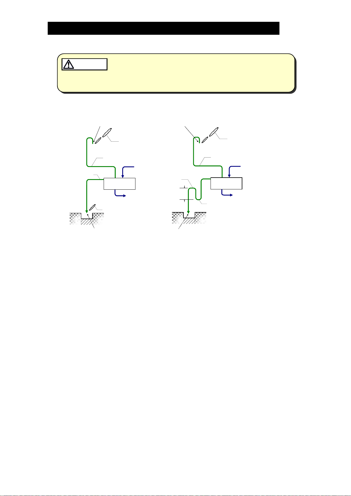
(7)Vent Pipe [Sv] and Overflow Pipe [Sf]:
•Be sure to install a vent pipe and an overflow pipe. Failure to install an
overflow pipe is dangerous, as condensate may spurt from the vent pipe
and could result in burns and other injuries.
•Pipe the vent pipe and the overflow pipe to a safe place such as a pit.
•Piping size of the overflow pipe should be the same or larger than
condensate inlet pipe.
WARNING
•Models other than the GP10L-1AJ
(12 in)
Condensate
Receiver
Flash Steam
Flash Steam
Condensate
Receiver
To PowerTrap
Flash Steam
Overflow Pipe Overflow Pipe
Condensate
Loop Seal
300 mm
(12 in)
1) 2) Flash Steam
Condensate
Receiver
Vent Pipe
Overflow Pipe Overflow Pipe
Condensate
NOTE:
This sketch is for explanation
purposes only and is not intended
as an installation design.
NOTE:
This sketch is for explanation
purposes only and is not intended
as an installation design.
Pipe the discharge to a safe place such as a pit.
High temperature steam or hot water may splash.
There is a possibility of condensed hot water dripping from vent pipe
outlet. Make sure to extend to where people do not pass.
Condensate
Receiver
Vent Pipe
Flash Steam
To PowerTrap
Flash Steam
The flow velocity in the pipe should be considered when determining the pipe
size.
1) If flash steam can be discharged from overflow pipe
Install overflow pipe and vent pipe separately.
2) If flash steam should not be released from overflow pipe (prevent flash
steam release)
Install overflow pipe and vent pipe separately. For overflow pipe, install loop
seal (approx. 300 mm (12 in)). Flash steam release from overflow pipe can
be prevented since water always accumulates at loop seal. Piping size
should be the same or larger than condensate inlet pipe.
NOTE: • There is a possibility of rust becoming clogged and/or corrosion
since water always present in the loop seal; the possibility is greater
if the piping diameter is too small (generally 25 mm (1 in) or smaller)
• If the loop seal becomes clogged, hot overflow water will blow from
vent pipe; make sure to install vent pipe to lead to a safe place
• Do not install loop seal on the vent pipe
Contact TLV if neither 1) nor 2) above can be installed.

172-65510MA-05 (GP Series System Package) 27 Dec 2016
12
• Model: GP10L-1AJ
Unlike other models, the GP10L-1AJ has an outlet port for the dual installation of
the overflow pipe and vent pipe. When installing the piping, connect the piping to
the flange on the top of the condensate receiver, and then install the overflow
pipe and vent pipe by separating each pipe as shown below.
Observe the same precautions as for other models for installation.
Overflow Pipe
Vent Pipe
(8)Check Valve to Prevent Return Water Hammer ①:
If length "A" in the following figure (from the PowerTrap to a rise in the piping) is
longer than 30 m (100 ft), return water hammer may occur in the piping after a
discharge cycle finishes. To prevent this, installation of a spring-return type check
valve just above the rise is recommended.
(9)Check Valve to Prevent Backflow Water Hammer ②:
If length "B" in the following figure is longer than 500 mm (1911/16 in) and steam
(including flash steam) enters the condensate recovery line, backflow water
hammer may occur in the piping. To prevent this, installation of a spring-return
type check valve close to the condensate recovery line is recommended.
VoCo
A
B
②
Backflow Water Hammer
Prevention Check Valve
①
Backflow Water
Hammer Prevention
Check Valve
Condensate
Recovery Line
[Sr]
TLV
Power
Trap
Steam with
condensate
When a layer
of steam exists
172-65510MA-05 (GP Series System Package) 27 Dec 2016
13
Installation and Maintenance Space
Anchoring the Body
Anchor the 4 corners of the base with anchor bolts. Anchor bolts are not supplied with
the system package, so prepare appropriate anchor bolts separately.
GP10L-1AJ: Anchor Bolt M12 ×4 pcs
Embedment depth of 50 mm (2 in) or more is recommended
GP14L-1AJ: Anchor Bolt M12 ×4 pcs
Embedment depth of 50 mm (2 in) or more is recommended
GP14M-1BJ: Anchor Bolt M12 ×4 pcs
Embedment depth of 50 mm (2 in) or more is recommended
GP10-1CJ: Anchor Bolt M16 ×4 pcs
Embedment depth of 150 mm (6 in) or more is recommended
GP10-2FJ: Anchor Bolt M16 ×4 pcs
Embedment depth of 150 mm (6 in) or more is recommended
Refer to the latest drawings for the anchoring positions of each model.
For the latest product information, please contact TLV.
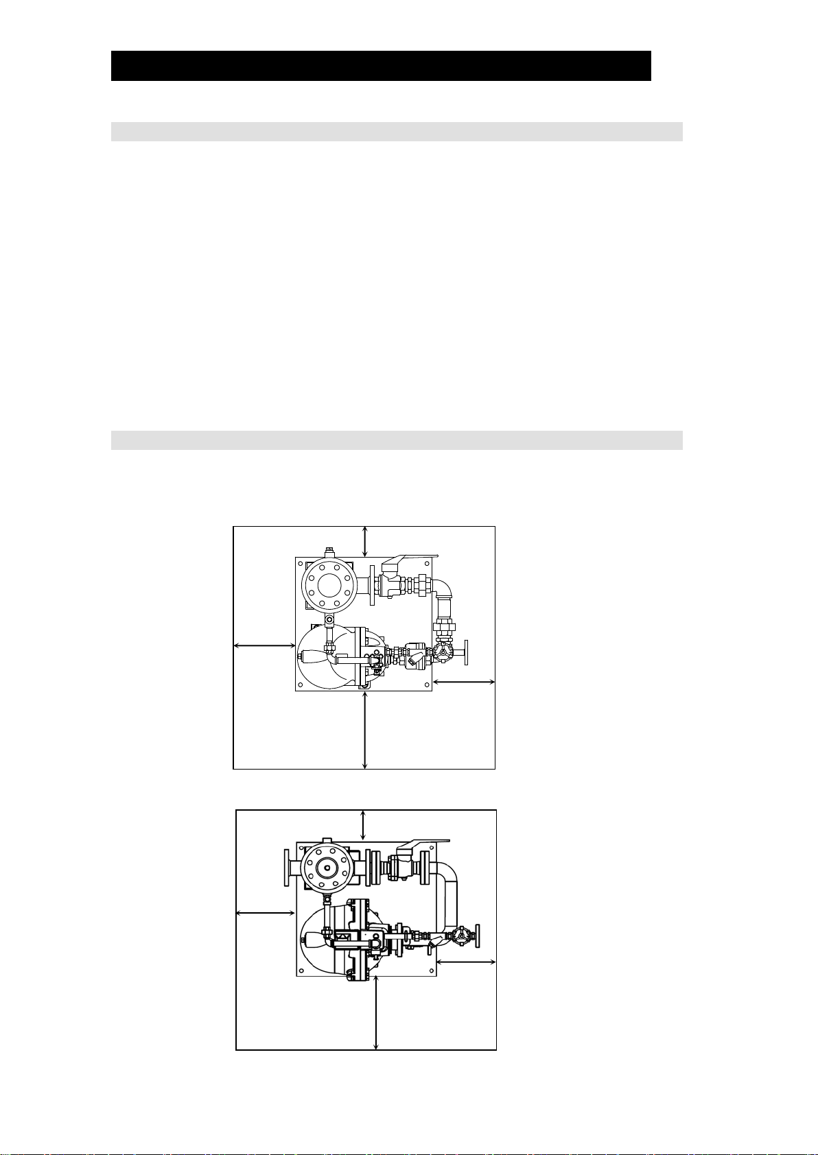
Maintenance Space
The maintenance space shown in the figure below should be provided to enable
disassembly, inspection and replacement of the system package. If there is
insufficient maintenance space, TLV may decline to perform maintenance work.
GP10-1AJ
200 mm (73/4in)
400 mm
(153/4in)
400 mm
(153/4in)
500 mm
(1911/16 in)
GP14L-1AJ
200 mm (73/4in)
400 mm
(153/4in)
400 mm
(153/4in)
500 mm
(1911/16 in)

172-65510MA-05 (GP Series System Package) 27 Dec 2016
14
GP14M-1BJ
400 mm
(15
3
/
4
in)
400 mm
(15
3
/
4
in)
800 mm
(30
1
/
2
in)
800 mm
(30
1
/
2
in)
GP10-1CJ
400 mm
(153/4in)
800 mm
(301/2in)
800 mm
(301/2in)
400 mm
(153/4in)
GP10-2FJ
800 mm
(301/2in)
800 mm
(301/2in) 800 mm
(301/2in)
500 mm
(1911/16 in)
172-65510MA-05 (GP Series System Package) 27 Dec 2016
15
Operation and Periodic Inspection
•After all piping work has been completed in accordance with the
specific piping system designed when the decision to utilize the
PowerTrap System Package was made, check once again to make sure
that all pipe connections have been tightened, gaskets have been
inserted where needed and all parts are securely installed.
•During commissioning and test runs, as well as during start-up of normal
operation, take measures to prevent people from coming into direct
contact with vent and overflow outlets. At the start-up of operation, large
quantities of condensate may flow, causing the Power Trap System
Package to momentarily overload. If this occurs, hot Condensate may
spurt from the pipe connections, the vent piping or overflow piping and
could result in burns, other injuries or damage to equipment.
WARNING
When disassembling or removing the product, wait until the internal
pressure equals atmospheric pressure and the surface of the product
has cooled to room temperature. Disassembling or removing the
product when it is hot or under pressure may lead to discharge of fluids,
causing burns, other injuries or damage.
CAUTION
During maintenance/disassembly all connections, piping and bolts should
be removed slowly to prevent fluids from spurting due to the release of
retained internal pressure. Failure to do so may result in burns or other
injury with the discharge of fluids.
CAUTION
Install properly and DO NOT use this product outside the recommended
operating pressure, temperature and other specification ranges.
Improper use may result in such hazards as damage to the product or
malfunctions which may lead to serious accidents. Local regulations
may restrict the use of this product to below the conditions quoted.
CAUTION
Be sure to use only the recommended components when repairing the
product, and NEVER attempt to modify the product in any way. Failure to
observe these precautions may result in damage to the product or burns
or other injury due to malfunction or the discharge of fluids.
CAUTION
Installation, inspection, maintenance, repairs, disassembly, adjustment and valve
opening/closing should be carried out only by trained maintenance personnel.
Operation
(1) Valve Operation
Refer to the drawings in "Installation" on page 8 to become familiar with the
symbols used for the various valves.
If water hammer has occurred, immediately cease operation and close any valves
that are operating.
a) Drain condensate in the condensate receiver by opening the condensate blow
valve [Vt], making sure the condensate blow valve [Vt] is piped to a safe area.
If the condensate receiver is filled up with condensate, condensate may spurt
from the vent pipe [Sv] during PowerTrap exhaust.
Make sure to close the condensate blow valve [Vt] after condensate is
drained.
b) Slowly open the exhaust valve [Ve].
c) Slowly open the valve [Vm] on the motive medium supply pipe. Make sure that
there is no sound of flow from the exhaust pipe [Se] or the check valve [Ci] on
the condensate inlet pipe.
d) Slowly open the valve [Vo] on the condensate outlet pipe.

172-65510MA-05 (GP Series System Package) 27 Dec 2016
16
e) Slowly open the valve [Vi] on the condensate inlet pipe.
The PowerTrap is normal if it operates intermittently; first exhausting the
motive medium to fill with condensate, and then taking in motive medium to
force the condensate out.
•The interval of operation will vary greatly depending on the amount of condensate
inflow, the temperature, the motive medium (steam or gas) and the motive
pressure. The interval of operation is considered to be the length of time between
the start of one discharge cycle and the start of the next discharge cycle.
•The interval of operation Tc (s) can be roughly determined using the following
formula:
GP10L-1AJ: Tc = 21,600/Q Tc = 47,600/Qp
GP14L-1AJ: Tc = 28,800/Q Tc = 63,500/Qp
GP14M-1BJ: Tc = 45,000/Q Tc = 99,200/Qp
GP10-1CJ/GP10-2FJ: Tc = 108,000/Q Tc = 238,000/Qp
Q : amount of inflowing condensate (kg/h)
Qp: amount of inflowing condensate (lb/h)
•The GP10L, GP14L, GP14M and GP10 condensate discharge capacity for each
discharge operation is listed below. The amount of time required for each
discharge operation will be between 3 and 30 seconds, depending on the back
pressure and the motive medium pressure.
GP10L-1AJ: approx. 6 liters (1.6 U.S. gal)
GP14L-1AJ: approx. 8 liters (2.1 U.S. gal)
GP14M-1AJ: approx. 12.5 liters (3.3 U.S. gal)
GP10-1CJ/GP10-2FJ*: approx. 30 liters (8 U.S. gal)
*Value per GP10
(2) If an error such as a leak or water hammer occurs after beginning operation of the
system package, shut off the valves immediately in the following order:
valve [Vm] on the motive medium supply pipe →valve [Vi] on the condensate inlet
pipe →valve [Vo] on the condensate outlet pipe →valve [Ve] on the exhaust pipe.
(3) Whenever any type of malfunction is suspected in the system package, refer to the
"Troubleshooting" in the corresponding product’s instruction manual, as shown
below:
System Package
Instruction Manual
GP10L-1AJ
GP14L-1AJ
GP14M-1BJ
PowerTrap GP10L/GT10L/GP14L/GT14L/GP14M/GT14M
GP10-1CJ
GP10-2FJ
PowerTrap GP10/GT10/GP14/GT14

172-65510MA-05 (GP Series System Package) 27 Dec 2016
17
Periodic Inspection and Diagnosis
There are two types of periodic inspection: the visual inspection and the disassembly
inspection.
(1)Visual Inspection
•As a general rule, this inspection should be performed at least once every 3 months.
•Check the following items:
a) There should be no leakage from the PowerTrap or from any of the
connections.
b) The PowerTrap unit should be operating cyclically (one indication being the
sharp, mechanical sound of the snap-action unit operating at the transition
between the filling and the discharge parts of the cycle). Immediately after
the end of the discharge part of the cycle and during the filling part of the
cycle, the sound of flow in the exhaust pipe should be heard. During the
pumping (discharge) part of the cycle, flow in the motive medium supply pipe
should be heard.
c) Condensate should not accumulate in the steam-using equipment, and the
temperature of the equipment should not be abnormally low.
d) There should be no condensate overflow from the overflow pipe or vent pipes.
e) There should be no continuous steam discharge through the vent pipe (it is
normal for the PowerTrap to release retained steam from the vent pipe after
motive steam forces the condensate discharge.)
f) There should not be any abnormal noise such as water hammer from the
condensate outlet pipe or the condensate recovery line while the
PowerTrap operates.
(2)Disassembly Inspection
•Only the PowerTrap unit(s) and check valves need disassembly inspection.
For the disassembly inspection, refer to the corresponding product’s instruction
manual.

172-65510MA-05 (GP Series System Package) 27 Dec 2016
18
Product Warranty
1. Warranty Period
One year following product delivery.
2. Warranty Coverage
TLV CO., LTD. warrants this product to the original purchaser to be free
from defective materials and workmanship. Under this warranty, the product
will be repaired or replaced at our option, without charge for parts or labor.
3. This product warranty will not apply to cosmetic defects, nor to any product
whose exterior has been damaged or defaced; nor does it apply in the
following cases:
1) Malfunctions due to improper installation, use, handling, etc., by other
than TLV CO., LTD. authorized service representatives.
2) Malfunctions due to dirt, scale, rust, etc.
3) Malfunctions due to improper disassembly and reassembly, or
inadequate inspection and maintenance by other than TLV CO., LTD.
authorized service representatives.
4) Malfunctions due to disasters or forces of nature.
5) Accidents or malfunctions due to any other cause beyond the control of
TLV CO., LTD.
4. Under no circumstances will TLV CO., LTD. be liable for consequential
economic loss damage or consequential damage to property.
* * * * * * *
For Service or Technical Assistance:
Contact your representative or your regional office.
Manufacturer
CO., LTD.
881 Nagasuna, Noguchi
Kakogawa, Hyogo 675-8511 JAPAN
Tel: 81-(0)79 - 427 - 1800
This manual suits for next models
4
Table of contents
Other TLV Water Pump manuals


