TLV PowerTrap GP10L User manual

PowerTrap
MODEL GP10L/GT10L/GP14L/GT14L/GP14M/GT14M
PowerTrap
TYP GP10L/GT10L/GP14L/GT14L/GP14M/GT14M
PowerTrap
MODÈLE GP10L/GT10L/GP14L/GT14L/GP14M/GT14M
GP10L/GT10L GP14M/GT14MGP14L/GT14L
INSTRUCTION MANUAL
Keep this manual in a safe place for future reference
MANUEL D UTILISATION
Conserver ce manuel dans un endroit facile d'accès
EINBAU- UND BETRIEBSANLEITUNG
Gebrauchsanleitung leicht zugänglich aufbewahren
PowerTrap
GP10L/GT10L/GP14L/GT14L/GP14M/GT14M
操作说明书
请务必妥善保管此说明书,以备日后之用
Copyright (C) 2023 by TLV CO., LTD. All rights reserved.
Deutsch
中
文
Français
English

Introduction
Thank you for purchasing the TLV PowerTrap. This product has been thoroughly
inspected before being shipped from the factory. When the product is delivered,
before doing anything else, check the specifications and external appearance to make sure
nothing is out of the ordinary. Also be sure to read this manual carefully before use and
follow the instructions to be sure of using the product properly.
If detailed instructions for special order specifications or options not contained in this
manual are required, please contact TLV for full details.
This instruction manual is intended for use with the model(s) listed on the front cover. It is
necessary not only for installation, but for subsequent maintenance, disassembly/reassembly
and troubleshooting. Please keep it in a safe place for future reference.
The English language instructions can be found on pages 3 – 36.
The contents of this manual are subject to change without notice.
Vorwort
Wir danken Ihnen für den Kauf von TLV PowerTrap. Dieses Produkt wurde nach
Fertigstellung sorgfältig geprüft und verließ unsere Fabrik vollständig und fehlerfrei. Wir
empfehlen Ihnen jedoch, gleich nach Erhalt den einwandfreien Zustand visuell zu
überprüfen und die Spezifikationen mit Ihren Bestellunterlagen zu vergleichen. Sollten Sie
dabei Abweichungen oder sonstige Fehler feststellen, bitten wir Sie,uns umgehend zu
benachrichtigen.
Wenden Sie sich bitte an TLV für Optionen oder Sonderausführungen, die nicht in dieser
Einbau- und Betriebsanleitung enthalten sind.
Diese Anleitung kann nur für Installation, Betrieb, Wartung, sowie Ausbau und Zusam-
menbau der auf der Vorderseite angegebenen Typen benutzt werden. Wir empfehlen,
vor Einbau und Inbetriebnahme die Anleitung sorgfältig durchzulesen und an einem
leicht zugänglichen Platz aufzubewahren, damit sie im Bedarfsfall zu Rate gezogen
werden kann.
Die Einbau- und Betriebsanweisung aut Deutsch befindet sich auf den Seiten 37 – 70.
Wir behalten uns vor, den Inhalt dieser Betriebsanleitung ohne Ankündigung zu ändern.
Introduction
Nous vous remercions d’avoir choisi le TLV PowerTrap. Ce produit a été inspecté
minutieusement avant de quitter l’usine. Toutefois, lors de sa livraison et avant toute chose,
nous vous conseillons de vérifier les spécifications et l’apparence externe de la pompe afin
de contrôler que tout est normal. Veuillez également lire ce manuel attentivement avant
d'utiliser la pompe, et suivre les instructions afin de l'utiliser correctement.
Si vous avez besoin d’instructions détaillées pour des options non contenues dans ce
manuel ou pour des spécifications relatives à des commandes particulières, veuillez
contacter TLV pour plus de détails.
Ce manuel est destiné aux modèles énumérés sur la page de couverture. Il est non
seulement nécessaire pour l'installation, mais également pour tout entretien,
démontage/remontage et détection de problèmes ultérieurs. Nous vous recommandons
de le garder dans un endroit sûr pour de futures consultations.
Le manuel d’utilisation en français se trouve aux pages 71 – 104.
Le contenu de ce manuel est sujet à modifications sans préavis.
Deutsch
Français
English
1

简介
感谢您购买TLV的PowerTrap。
本产品经过全面的性能质量检测,检测合格后方出厂。在产品运抵时,请先检查相关参数及产品外形是
否正确。在使用本产品前请务必仔细阅读本说明书,只有严格遵守本说明书中的要求进行操作,才能确保产
品的正确使用。
本说明书中未涉及特殊型号PowerTrap或选配件的相关说明,如需此类资料,请与TLV公司联系索取。
本说明书只适用于封面中列出的型号并提供安装、维护保养、拆卸/装配以及故障诊断方面的须知。请
务必妥善保管此说明书,以备日后之用。
中文说明书可以在第105-136页找到。
本说明书的内容可能随时更改,恕不另行通知。
2
中
文

Contents
Safety Considerations………………………………………………....……....……....…….... 4
General Description…………………………….....……………............................................. 6
Application……………………………………………………………………………….……...........…
6
Operation……………………………………………………………………………….…….............. 7
Specifications……………………………………………………………………………….……..... 8
Configuration……………………………………………………………………………….……....... 8
Installation……………………………………………………………………………….……...........
10
Open System Piping (Steam System Example) ………………….…………………………..........
10
Closed System Piping (Steam System Example) ………………………………………………......
11
Installation Procedure ……………………………………………………………………………........
12
Sizing the Condensate Receiver / Reservoir ………………………………………………………..
17
Installing Several PowerTrap Units in Parallel ………………………………………………….... 20
Installation and Maintenance Space…………………………………………………. 21
Anchoring the Body ………………………………………………………………………………....... 21
Maintenance Space ………………………………………………………………………………..…..
21
Operation and Periodic Inspection…………………..……........……..........…...........
22
Operation………………………………………………………….….….….….….….….……..….......
22
Periodic Inspection and Diagnosis………………………………………………………...….......….
23
Disassembly / Reassembly……………..……..........…..................................................
24
Replacement Parts …………………………………………………….............................................
25
Recommended Tools List for Disassembly / Reassembly……………………………….......…....
26
1. Removing / Reattaching the Body from / to the Cover…………………………………............
27
2. Removing / Reattaching the Float …………………………………………………….……......... 28
3. Separating / Rejoining the Trap Rod and Trap Unit (GT10L/GT14L/GT14M only) …............ 29
4. Removing / Reattaching the Trap Unit (GT10L/GT14L/GT14M only) …………….................. 29
5. Removing / Reattaching the Snap-action Unit …………………........….......….......….............
30
6. Removing / Reinstalling the Motive Medium Intake and Exhaust Valves ..…...………...........
30
7. Removing / Reinstalling the Motive Medium Intake and Exhaust Valve Seats …...……........
31
Troubleshooting………………………………..………...………...........……………..…….......32
Determining the Problem from the Symptoms ………………………………………………..........
32
Types of Failure and their Causes ……………………………………………………………........…
33
Causes and Corrective Measures …………………………………………………………...............
34
TLV EXPRESS LIMITED WARRANTY…………………..……..........…................. 137
Service……………..……..........…...........……………..……..........…...........……………..…….
145
English
3
Safety Considerations
• Read this section carefully before use and be sure to follow the instructions.
• Installation, inspection, maintenance, repairs, disassembly, adjustment and valve
opening/closing should be carried out only by trained maintenance personnel.
• The precautions listed in this manual are designed to ensure safety and prevent equipment
damage and personal injury. For situations that may occur as a result of erroneous handling,
three different types of cautionary items are used to indicate the degree of urgency and the
scale of potential damage and danger: DANGER, WARNING and CAUTION.
• The three types of cautionary items above are very important for safety: be sure to observe all
of them as they relate to installation, use, maintenance and repair. Furthermore, TLV accepts no
responsibility for any accidents or damage occurring as a result of failure to observe these
precautions.
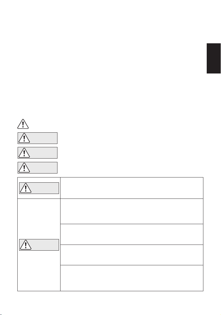
WARNING
Indicates an urgent situation which poses a threat of death or
serious injury
DANGER
CAUTION
Indicates that there is a possibility of injury or equipment / product
damage
Symbols
Indicates a DANGER, WARNING or CAUTION item.
CAUTION
WARNING
NEVER apply direct heat to the float.
The float may explode due to increased internal pressure, causing
accidents leading to serious injury or damage to property and
equipment.
Install properly and DO NOT use this product outside the recommended
operating pressure, temperature and other specification ranges.
Improper use may result in such hazards as damage to the product or
malfunctions that may lead to serious accidents. Local regulations may
restrict the use of this product to below the conditions quoted.
Use hoisting equipment for heavy objects (weighing approximately
20 kg (44 lb) or more).
Failure to do so may result in back strain or other injury if the object
should fall.
Take measures to prevent people from coming into direct contact
with product outlets.
Failure to do so may result in burns or other injury from the discharge of
fluids.
When disassembling or removing the product, wait until the internal
pressure equals atmospheric pressure and the surface of the
product has cooled to room temperature.
Disassembling or removing the product when it is hot or under pressure
may lead to discharge of fluids, causing burns, other injuries or damage.
Safety considerations are continued on the next page.
Indicates that there is a potential threat of death or serious injury
4
English

CAUTION
Do not use excessive force when connecting threaded pipes to the
product.
Over-tightening may cause breakage leading to fluid discharge, which may
cause burns or other injury.
Be sure to use only the recommended components when repairing
the product, and NEVER attempt to modify the product in any way.
Failure to observe these precautions may result in damage to the
product and burns or other injury due to malfunction or the discharge of
fluids.
Use only under conditions in which no freeze-up will occur.
Freezing may damage the product, leading to fluid discharge, which may
cause burns or other injury.
Use only under conditions in which no water hammer will occur.
The impact of water hammer may damage the product, leading to fluid
discharge, which may cause burns or other injury.
Take measures to ensure the proper handling, such as recovery or
dilution, of hazardous fluids discharged at product outlets.
Outflow of fluid or fluid leaks may lead to hazards such as flammable
conditions or corrosion, which may result in injury, fires, damage or
other accidents.
English
5

Install properly and DO NOT use this product outside the recommended
operating pressure, temperature and other specification ranges.
Improper use may result in such hazards as damage to the product or
malfunctions which may lead to serious accidents. Local regulations
may restrict the use of this product to below the conditions quoted.
CAUTION
・No need for external steam trap
(GT model features built-in trap)
・No flash steam discharge
・Small reservoir
・Use with vacuum equipment possible
・Only one piece of equipment
possible per system
・Equipment has minimum height
requirement to ensure that
condensate flows naturally, by gravity
(GT10L: approx. 0.3 m or 0.5 m
(12 or 20 in)
GT14L: approx. 0.3 m (12 in),
GT14M: approx. 0.35 m (14 in))
・Collection of condensate from multiple
equipment possible
・Can be used where trap is lower than
receiver, such as equipment situated near
grade (providing there is sufficient
differential pressure)
・Separate steam trap required for each
piece of equipment
・Requires venting pipe to discharge flash
steam to atmosphere
Mechanical pump
GP10L/GP14L/GP14M
Mechanical pump with built-in trap
GT10L/GT14L/GT14M
Where there is ALWAYS a
negative pressure differential
(e.g. vacuum equipment),
GP10L/GP14L/GP14M can be used
System
Overview
General Description
Closed System Open System
Application
The PowerTrap is used to discharge liquid from vacuum-pressure or low-pressure areas to
high-pressure areas, or from lower to higher elevations.
The GT model is the same as the GP, but with an additional steam trap function, making it
suitable for use in instances in which the inlet pressure may alternately be lower than or higher
than the outlet pressure.
There are two types of delivery systems (piping methods): the closed system and the open
system. Use of the GT model or the GP model is determined by the type of system. Check to
make sure that the PowerTrap model that has been purchased is suitable for use on the type of
system that is being planned for installation.
Power
Trap
Power
Trap
Type of System
Benefits
Notes
Model
6
English

Body
Exhaust Valve
(open)
Inlet Check
Valve
Float Trap Unit
Cover
Intake Valve (closed)
(Motive Medium) Exhaust Valve
(close)
Intake Valve (open)
(motive medium)
Outlet Check
Valve
Pumped Medium
Inlet Pipe
Inlet Check Valve
Outlet Check Valve
Condensate
Outlet Pipe
(1) Condensate Inflow (2) Condensate Discharge
EnglishEnglish
Operation
(1) When condensate flows from the condensate inlet pipe through the inlet check valve into the
body of the unit, the air in the body escapes through the exhaust valve (which equalizes the
internal pump pressure to the pressure of the condensate source) and the float rises, as
shown in (1) below.
• In the case of the GT, the main valve on the trap unit opens as the float rises.
When Pi > Pb(when the inlet pressure (Pi) is greater than the back pressure
(Pb)), the condensate passes through the outlet check valve and is discharged
through the condensate outlet pipe (normal trapping function).
• When Pi ≤Pbfor both the GP and GT models, the condensate is not discharged and
collects in the body of the unit.
(2) When the float rises to its high level, the push rod on the snap-action unit rises quickly,
simultaneously closing the exhaust valve and opening the intake (motive medium) valve.
The pressure supplied by the motive medium causes the internal pressure in the unit to
become greater than the back pressure. The inlet check valve closes and the outlet check
valve is pushed open, thus discharging the condensate in the unit through the outlet pipe,
as shown in (2) below.
(3) As a result of the condensate in the unit being discharged, the water level in the unit drops
and the float descends. When the float reaches its low level, the push rod on the
snap-action unit moves down quickly, simultaneously opening the exhaust valve and closing
the intake (motive medium) valve and the status reverts to that shown in (1) below.
CAUTION Take measures to prevent people from coming into direct contact with
product outlets. Failure to do so may result in burns or other injury from
the discharge of fluids.
English
7
Exhaust
Outlet
⑩⑦ ⑩
⑩⑩ ⑥⑥ ①① ⑩②②③③ ⑪⑪
⑨ ⑧
Condensate
Inlet
Motive Medium
Inlet
Condensate
Outlet
These screw
holes are for
the flange
connection
Detail of Intake / Exhaust
Valve and Valve Seat
⑤⑤
④
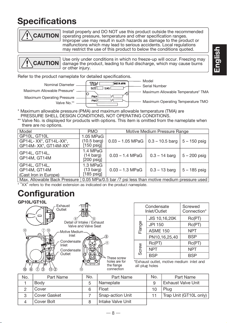
Specifications
* Maximum allowable pressure (PMA) and maximum allowable temperature (TMA) are
PRESSURE SHELL DESIGN CONDITIONS, NOT OPERATING CONDITIONS.
** Valve No. is displayed for products with options. This item is omitted from the nameplate when
there are no options.
Configuration
GP10L/GT10L
CAUTION Install properly and DO NOT use this product outside the recommended
operating pressure, temperature and other specification ranges.
Improper use may result in such hazards as damage to the product or
malfunctions which may lead to serious accidents. Local regulations
may restrict the use of this product to below the conditions quoted.
CAUTION Use only under conditions in which no freeze-up will occur. Freezing may
damage the product, leading to fluid discharge, which may cause burns
or other injury.
Refer to the product nameplate for detailed specifications.
Nominal Diameter
Maximum Allowable Pressure*
Maximum Operating Pressure
Valve No.**
Model
Serial Number
Maximum Allowable Temperature* TMA
Maximum Operating Temperature TMO
No.
1
2
3
4
No.
5
6
7
8
No.
9
10
11
Part Name Part Name
Body
Cover
Cover Gasket
Cover Bolt
Exhaust Valve Unit
Plug
Trap Unit (GT10L only)
Part Name
Nameplate
Float
Snap-action Unit
Intake Valve Unit
Condensate
Inlet/Outlet Screwed
Connection*
FlangeScrew
JIS 10,16,20K
JPI 150
ASME 150
PN10,16,25,40
Rc(PT)
NPT
BSP
Rc(PT)
Rc(PT)
NPT
BSP
Rc(PT)
NPT
BSP
*Exhaust outlet, motive medium
inlet and
all plug holes
GP10L, GT10L
GP14L- XX*, GT14L-XX*,
GP14M- XX*, GT14M-XX*
GP14L, GT14L,
GP14M, GT14M
GP14L, GT14L,
GP14M, GT14M
(Cast Iron in Europe)
Max. Allowable Back Pressure
Model PMO
0.03 – 1.05 MPaG
0.03 – 1.4 MPaG
0.03 – 1.3 MPaG
1.05 MPaG
(10.5 barg)
[150 psig]
1.4 MPaG
(14 barg)
[200 psig]
1.3 MPaG
(13 barg)
[185 psig]
0.3 – 10.5 barg
0.3 – 14 barg
0.3 – 13 barg
5 – 150 psig
5 – 200 psig
5 – 185 psig
0.05 MPa/0.5 bar /7 psi less than motive medium pressure used
Motive Medium Pressure Range
* ”XX” refers to the model extension as indicated on the product nameplate.
8
English
Exhaust Outlet
⑩⑦⑩
⑩⑥ ① ②
⑤
③
⑨ ⑧
Condensate
Inlet
Motive Medium
Inlet
Condensate
Outlet
These screw
holes are for
the flange
connection
Detail of Intake / Exhaust Valve
and Valve Seat
⑩
⑪
④
Exhaust Outlet
⑩⑩ ⑥⑥ ①① ②②
⑤⑤
③③
⑨ ⑧
Condensate
Inlet
Motive Medium
Inlet
Condensate
Outlet
These screw
holes are for
the flange
connection
Detail of Intake / Exhaust Valve
and Valve Seat
①
⑪⑪
④
⑩⑦
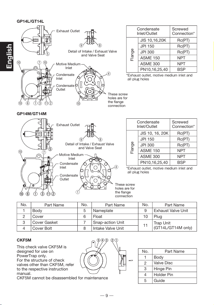
GP14L/GT14L
GP14M/GT14M
①①②②③③④④⑤⑤
No.
1
2
3
4
No.
5
6
7
8
No.
9
10
11
Part Name Part Name
Body
Cover
Cover Gasket
Cover Bolt
Exhaust Valve Unit
Plug
Trap Unit
(GT14L/GT14M only)
Part Name
Nameplate
Float
Snap-action Unit
Intake Valve Unit
No.
1
2
3
4
5
Part Name
Body
Valve Disc
Hinge Pin
Holder Pin
Guide
Condensate
Inlet/Outlet Screwed
Connection*
Flange
JIS 10,16,20K
JPI 150
JPI 300
ASME 150
ASME 300
PN10,16,25,40
Rc(PT)
Rc(PT)
Rc(PT)
NPT
NPT
BSP
*Exhaust outlet, motive medium inlet and
all plug holes
Condensate
Inlet/Outlet Screwed
Connection*
Flange
JIS 10, 16, 20K
JPI 150
JPI 300
ASME 150
ASME 300
PN10,16,25,40
Rc(PT)
Rc(PT)
Rc(PT)
NPT
NPT
BSP
*Exhaust outlet, motive medium inlet and
all plug holes
This check valve CKF5M is
designed for use on
PowerTrap only.
For the structure of check
valves other than CKF5M, refer
to the respective instruction
manual.
CKF5M cannot be disassembled for maintenance
CKF5M
English
9
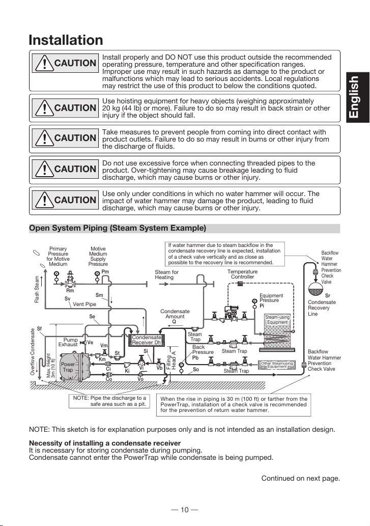
Installation
Open System Piping (Steam System Example)
CAUTION Install properly and DO NOT use this product outside the recommended
operating pressure, temperature and other specification ranges.
Improper use may result in such hazards as damage to the product or
malfunctions which may lead to serious accidents. Local regulations
may restrict the use of this product to below the conditions quoted.
CAUTION Use hoisting equipment for heavy objects (weighing approximately
20 kg (44 lb) or more). Failure to do so may result in back strain or other
injury if the object should fall.
CAUTION Take measures to prevent people from coming into direct contact with
product outlets. Failure to do so may result in burns or other injury from
the discharge of fluids.
CAUTION Do not use excessive force when connecting threaded pipes to the
product. Over-tightening may cause breakage leading to fluid
discharge, which may cause burns or other injury.
CAUTION Use only under conditions in which no water hammer will occur. The
impact of water hammer may damage the product, leading to fluid
discharge, which may cause burns or other injury.
NOTE: This sketch is for explanation purposes only and is not intended as an installation design.
Necessity of installing a condensate receiver
It is necessary for storing condensate during pumping.
Condensate cannot enter the PowerTrap while condensate is being pumped.
Continued on next page.
Ci
Vo
Km
Co
Vm
Ve
Vi
Pb
Se
Si
So
Sr
Ki
St
Sv
Vb
Sf
Q
Pm
Sm
Rm
Back
Pressure
Steam Trap
Steam Trap
Steam
Trap
Temperature
Controller
Pi
Equipment
Pressure
Steam for
Heating
Vent Pipe
Steam-using
Equipment
Max. Height
3m (10 ft)
Flash Steam
Overflow Condensate
Condensate
Recovery
Line
Backflow
Water
Hammer
Prevention
Check
Valve
Backflow
Water Hammer
Prevention
Check Valve
If water hammer due to steam backflow in the
condensate recovery line is expected, installation
of a check valve vertically and as close as
possible to the recovery line is recommended.
NOTE: Pipe the discharge to a
safe area such as a pit. When the rise in piping is 30 m (100 ft) or farther from the
PowerTrap, installation of a check valve is recommended
for the prevention of return water hammer.
Condensate
Amount
Motive
Medium
Supply
Pressure
Primary
Pressure
for Motive
Medium
Pump
Exhaust
Filling
Head A
Dh
Condensate
Receiver
Other Steamusing
Equipment
Power
Trap
10
English

Closed System Piping (Steam System Example)
NOTE: This sketch is for explanation purposes only and is not intended as an installation design.
In closed system applications, the motive medium must be compatible with the liquid
being pumped. If a non-condensable gas such as air or nitrogen is used as the motive
medium, please consult TLV for assistance.
Q
A
Pm
Pb
Si
So
Sr
Sm
Se
Sv
Sf
Dh
Ci
Co
Ki
Km
Rm
Pi
St
Vi
Vo
Vm
Ve
Vb
Condensate Amount
Filling Head
Motive Medium Supply Pressure
Back Pressure
Condensate Inlet Pipe
Condensate Outlet Pipe
Condensate Recovery Line
Motive Medium Supply Pipe
Exhaust Pipe
Vent Pipe
Overflow Pipe
Condensate Receiver
Condensate Inlet Check Valve
Condensate Outlet Check Valve
Condensate Inlet Strainer
Motive Medium Strainer
Motive Medium Pressure
Reducing Valve
Equipment Pressure
Steam Trap on Drip leg
Valve on Condensate Inlet Pipe
Valve on Condensate Outlet Pipe
Valve on Motive Medium Supply Pipe
Valve on Exhaust Pipe
Blowdown Valve
NOTE: Pipe the discharge to a
safe area such as a pit.
*
*Products shown in the may be replaced with a valve.
When the rise in piping is 30 m (100 ft) or farther from the
PowerTrap, installation of a check valve is recommended
for the prevention of return water hammer.
If water hammer due to steam backow in the
condensate recovery line is expected, installation
of a check valve vertically and as close as
possible to the recovery line is recommended.
Vo
So
Vb
Pb
Co
GT
Power
Trap
Km
Backow
Water Hammer
Prevention
Check Valve
Back
Pressure
St
Vm
Condensate
Reservoir Dh
Steam-using
Equipment
Ve
Pump
Exhaust
Air and Non-condensate
Gas Discharge
Filling
Head A
Condensate
Recovery
Line
Condensate
Amount Q
Ca
Va
Se
Sm
Sv
Rm
Backow
Water Hammer
Prevention
Check Valve
Equipment
Pressure
Pi
Temperature
Controller
Steam for
Heating
Motive
Medium
Supply
Pressure
Pm
Motive
Medium
La
Sr
Ci Ki Vi Si
Q
A
Pm
Pb
Si
So
Sr
Sm
Se
Sv
Dh
GT
Ci
Co
Ca
La
Ki
Km
Pi
Rm
St
Vi
Vo
Vm
Ve
Va
Vb
Condensate Amount
Filling Head
Motive Medium Supply Pressure
Back Pressure
Condensate Inlet Pipe
Condensate Outlet Pipe
Condensate Recovery Line
Motive Medium Supply Pipe
Exhaust Pipe
Vent Pipe
Condensate Reservoir
PowerTrap
Condensate Inlet Check Valve
Condensate Outlet Check Valve
Check Valve for Air Vent
Air Vent (for Steam)
Condensate Inlet Strainer
Motive Medium Strainer
Equipment Pressure
Motive Medium Reducing Valve
Steam Trap on Drip Leg
Valve on Condensate Inlet Pipe
Valve on Condensate Outlet Pipe
Valve on Motive Medium Supply Pipe
Valve on Exhaust Pipe
Valve for Air/Gas Discharge
Blowdown Valve
English
11

Installation Procedure
Refer to the systems outlined in the “General Description” section on page 6 to select the correct
system and model (GT or GP) for the application. Installation, inspection, maintenance, repairs,
disassembly, adjustment and valve opening/closing should be carried out only by trained
maintenance personnel.
(1) Pumped Medium:
• Fluids that can be discharged through the PowerTrap are limited to steam condensate
and water. PowerTraps that have been specially constructed for other specific fluids are
not limited by this restriction.
(2) Motive Medium Supply Piping:
• The motive medium supply pipe diameter should be at least 15 mm ( in).
• Install a 40-mesh or finer strainer on the PowerTrap motive medium supply pipe, as close
to the PowerTrap as possible, while allowing sufficient space for maintenance of the
strainer. Strainers should be angled in the 3 or 9 o’clock positions for horizontal
installations.
• See “Specifications” on page 8 for the maximum motive medium inlet pressure.
• For Open Systems: Steam, compressed air or nitrogen may be used as the motive
medium.
• For Closed Systems: Use steam as the motive medium. Except in special cases, do not
use non-condensable gases such as air or nitrogen.
• When the motive medium is steam, if the application will require that the equipment be shut
down (non-operating) for periods of 2 months or longer, install piping connecting the
motive medium supply line to the receiver/reservoir pipe, being sure to install a drip leg on
the motive medium supply line, and a steam trap in the drip leg (between where it branches
to go to the PowerTrap and where it enters the receiver/reservoir pipe). (See item [St] in the
drawings on pages 10 and 11.)
This measure is not necessary when the motive medium is compressed air or nitrogen.
(3) Pressure Reducing Valve on the Motive Medium Supply Piping:
• When the supply pressure of the motive medium is greater than the maximum operating
pressure of the PowerTrap, install a TLV COSPECT Series pressure reducing valve. Make
sure that the motive medium pressure is lower than the maximum operating pressure of the
PowerTrap. Use good piping practices when selecting the installation location for
COSPECT. In this case, be sure to install a safety valve between the pressure reducing
valve and the PowerTrap.
• When the supply pressure of the motive medium is less than the maximum operating
pressure of the PowerTrap, if a pressure reducing valve is to be installed to slow the speed
of the flow, the installation of a safety valve is not required.
• Install the pressure reducing valve as far away from the PowerTrap as possible. When the
motive medium pressure is less than 0.5 MPaG (72.5 psig, 5 barg): at
least 3 m (10 ft)
When the motive medium pressure is 0.5 MPaG or greater (72.5 psig or greater, 5 barg
or greater): at least 3 m + 1 m / 0.1 MPaG (1 barg) over 0.5 MPaG (5 barg)
(10 ft + 1 ft / 4.5 psig over 72.5 psig)
• The pressure setting on the pressure reducing valve should be between 0.05 and 0.15 MPa
(7 – 20 psi, 0.5 – 1.5 bar) higher than the back pressure.
When the discharge capacity of the PowerTrap is insufficient for the set motive pressure,
increase this set pressure even further.
/
12
12
English

Figure 1: Open Systems Figure 2: Open & Closed Systems
* For Open Systems only
When the exhaust piping height exceeds 3 m (10 ft.)
Vent Line
Equipment
When the
exhaust
piping is
3 m (10 ft.)
or more
Outlet
Pipe
Inlet
Pipe
Pit
Close to
Pit
Pit
Exhaust
Piping Receiver
Overflow
Pipe
Steam
Trap
Vent Line*
Receiver/
Reservoir
Check
Valve
Pit
Outlet
Pipe
Inlet
Pipe
Exhaust
Piping
Overflow
Pipe*
Pit
Close to
When the
exhaust
piping is
3 m (10 ft.)
or more
Equipment
Receiver/
Reservoir
Power
Trap Power
Trap
Power
Trap Power
Trap
(5) Inlet and Outlet Piping
• Install a 40-mesh or finer strainer on the PowerTrap pumped medium inlet pipe.
The installation should be in a location that allows sufficient space for maintenance
of the strainer.
• Ensure the inlet and outlet check valves are installed in the correct direction. The
check valve on the inlet pipe in particular should be installed right next to the PowerTrap.
(4) Exhaust Piping:
• The exhaust pipe diameter should be at least 15 mm ( in).
• The exhaust pipe should be connected to the top of the receiver/reservoir.
• For Open Systems: If the GP exhaust line has to discharge to atmosphere, a sound level of
approximately 90 dB may be emitted from the exhaust pipe discharge outlet for two to three
seconds. If soundproofing measures are necessary, install a silencer. (If the exhaust line is
connected to the condensate receiver, the sound level will be below 60 dB.)
• Make sure that the distance from the ground to the highest point on the exhaust pipe
(where it enters the receiver/reservoir pipe) does not exceed 3 m (10 ft).
If it exceeds 3 m (10 ft), condensate must be drained from the exhaust pipe in order not to
obstruct the exhaust. Implement one of the following countermeasures:
(See the figures below.)
(a) For Open Systems only: Add a float-type steam trap to the exhaust pipe at a point just
above where the exhaust pipe exits the unit body. (Figure 1)
(b) For Open and Closed Systems: Add piping connecting the exhaust pipe to the
condensate inlet pipe between the reservoir pipe and the strainer, being sure to
install a check valve on the piping to prevent backflow of condensate from the
condensate inlet pipe to the exhaust pipe. (Figure 2)
• For Closed Systems only: The exhaust pipe must be connected to the top of the reservoir.
Make sure that the arrow
on the check valve matches
with the direction of flow.
/
12
13
English
Stud Bolt
Gaskets
Install with the “ ” mark
pointing upwards.
Fit guides to stud bolts.
Inlet
Outlet
Inlet
Outlet
Inlet
Outlet
Inlet
Outlet
Inlet
Outlet
Inlet
Outlet
Inlet
Outlet
Inlet
Outlet
Inlet
Outlet
Inlet
Outlet
Inlet
Outlet
25
25
25
25
25
25
40
25
40
25
40
25
40
25
40
40
40
40
40
40
40
40
(1)
(1)
(1)
(1)
(1)
(1)
(1 )
(1)
(1 )
(1)
(1 )
(1)
(1 )
(1)
(1 )
(1 )
(1 )
(1 )
(1 )
(1 )
(1 )
(1 )
M12 90 mm
in-13 UNC 3 in
M16 90 mm
M16 100 mm
M12 80 mm
in-13 UNC 4 in
in-13 UNC 3 in
in-10 UNC 4 in
in-11 UNC 3 in
M16 100 mm
M16 80 mm
M16 ×100 mm
in-13 UNC ×4 in
in-10 UNC ×4 in
M16 ×100 mm
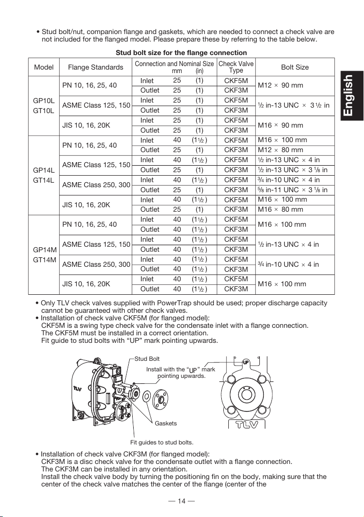
• Stud bolt/nut, companion flange and gaskets, which are needed to connect a check valve are
not included for the flanged model. Please prepare these by referring to the table below.
• Only TLV check valves supplied with PowerTrap should be used; proper discharge capacity
cannot be guaranteed with other check valves.
• Installation of check valve CKF5M (for flanged model):
CKF5M is a swing type check valve for the condensate inlet with a flange connection.
The CKF5M must be installed in a correct orientation.
Fit guide to stud bolts with “UP” mark pointing upwards.
• Installation of check valve CKF3M (for flanged model):
CKF3M is a disc check valve for the condensate outlet with a flange connection.
The CKF3M can be installed in any orientation.
Install the check valve body by turning the positioning fin on the body, making sure that the
center of the check valve matches the center of the flange (center of the
Model Flange Standards
Connection and Nominal Size
mm (in)
Check Valve
Type
Bolt Size
/
12
/
12
/
12
/
12
/
12
/
12
/
12
/
12
/
12
/
12
/
12
/
12
/
12
/
12
/
12/
18
/
18
/
12
/
34
/
12
/
34
/
58
PN 10, 16, 25, 40
ASME Class 125, 150
JIS 10, 16, 20K
PN 10, 16, 25, 40
ASME Class 125, 150
ASME Class 250, 300
JIS 10, 16, 20K
PN 10, 16, 25, 40
ASME Class 125, 150
ASME Class 250, 300
JIS 10, 16, 20K
CKF5M
CKF3M
CKF5M
CKF3M
CKF5M
CKF3M
CKF5M
CKF3M
CKF5M
CKF3M
CKF5M
CKF3M
CKF5M
CKF3M
CKF5M
CKF3M
CKF5M
CKF3M
CKF5M
CKF3M
CKF5M
CKF3M
×
×
×
×
×
×
×
×
×
×
×
GP10L
GT10L
GP14L
GT14L
GP14M
GT14M
Stud bolt size for the flange connection
14
English

(7) Receiver/Reservoir Pipe and Filling Head
• Please refer to “Sizing the Condensate Receiver/Reservoir” on pages 17 - 19.
The size and vent pipe aperture are determined by (a) the amount of flash steam in
the in-flowing condensate (pumped medium) and (b) the amount of pumped
medium held back while the PowerTrap is discharging.
If the receiver is small, the flow of flash steam may cause the condensate to flow
out the vent pipe.
If the vent pipe size is small, the pressure in the receiver will rise, restricting the
pumped medium inflow.
Be sure to select a receiver/reservoir pipe of the correct size.
• The filling head represents the distance from the bottom of the PowerTrap (from
grade) to the bottom of the receiver/reservoir.
The standard filling head is 630 mm (25 in).
When an installation calls for a lower filling head, a filling head of less than 630 mm
(25 in) is allowable. However, filling heads lower than the minimum filling heads
listed below must not be used:
piping). If the center of the check valve is off the center, the pumped medium inflow
will be impaired, resulting in reducing the performance ability of the PowerTrap.
TLV CK3MG
TLV CKF5M
Inlet Check Valve Model
GP/GT10L: 450 mm (18 in)
GP/GT10L: 300 mm (12 in)
GP/GT14L: 300 mm (12 in)
GP/GT14M: 350 mm (14 in)
Minimum Filling Head
• For Open Systems:
- If venting flash steam to a high area, an overflow pipe must be installed to
discharge condensate to a safe area.
- An overflow pipe should be installed at the side of the receiver.
(6) Valves on the Various Pipes
• In order to ensure the proper discharge capacity, use full bore ball valves or gate
valves on the pumped medium inlet and outlet lines as well as on the motive
medium supply and exhaust lines.
If it is necessary to reduce the velocity of the motive medium supply, a needle valve
can be used. However, be aware that the discharge capacity will be reduced.
(Refer to “Operation” (1) e) on pages 22 and 23.)
• Install union or flanged joints between the valves and the PowerTrap to allow for
easy maintenance.
• Be sure to provide the necessary maintenance space for PowerTrap disassembly
and repair (see “Installation and Maintenance Space” on page 21).
Tap positioning fin to turn check valve until
each fin touches its adjacent stud bolt.
Stud Bolt
Gaskets
Positioning Fin
15
English

Examples of Overflow Piping for Open Systems
Explanations for overflow piping for open systems
1) If flash steam can be discharged from overflow pipe
Install overflow pipe and vent pipe separately.
2) If flash steam should not be released from overflow pipe (prevent flash steam release)
Install overflow pipe and vent pipe separately. For overflow pipe, install loop seal (approx.
300 mm (12 in)). Flash steam release from overflow pipe can be prevented since water
always accumulates at loop seal. Piping size should be the same or larger than
condensate inlet pipe.
• For Closed Systems: An air vent for steam [La] is required to discharge the initial
air in the steam-using equipment and the condensate reservoir pipe or any gas
generated in the system. In this case, installing the check valve for air vent [Ca] will
prevent air from being sucked in from the outlet of the vent pipe [Sv]. This check
valve must be installed when the pressure inside the piping becomes negative. A
valve for air discharge [Va] can be installed instead of the air vent (for steam) [La]
and check valve for air vent [Ca].
When releasing the initial air using a valve for air discharge, leave the valve for air
discharge [Va] slightly open until the PowerTrap has cycled 2 – 3 times. Close the
valve for normal operation.
NOTE: • There is a possibility of rust becoming clogged and/or corrosion since water
always present in the loop seal; the possibility is greater if the piping diameter is
too small (generally 25 mm (1 in) or smaller)
• If the loop seal becomes clogged, hot overflow water will blow from vent pipe;
make sure to install vent pipe to lead to a safe place
• Do not install loop seal on the vent pipe
Contact TLV if neither 1) nor 2) above can be installed.
WARNING
・
Be sure to install a vent pipe and an overflow pipe. Failure to install an
overflow pipe is dangerous, as condensate may spurt from the vent
pipe and could result in burns and other injuries.
・Pipe the vent pipe and the overflow pipe to a safe place such as a pit.
・Piping size of the overflow pipe should be the same or larger than
condensate inlet pipe.
To PowerTrap
Condensate
Loop Seal
300 mm
(12 in)
1) 2) Flash Steam
Condensate
Receiver Condensate
Receiver
Vent Pipe
Overflow Pipe Overflow Pipe
Condensate
Pipe the discharge to a safe place such as a pit.
High temperature steam or hot water may splash.
There is a possibility of condensed hot water dripping from vent
outlet. Make sure to extend to where people do not pass.
Vent Pipe
Flash Steam
To PowerTrap
Flash Steam
16
English

(8) Velocity at Outlet Piping
The PowerTrap uses the motive medium supply pressure to push out the condensate in the
trap.
• Discharge capacity of pumped medium for each discharge operation:
GP10L/GT10L :approximately 6 liters (1.6 U.S. gal)
GP14L/GT14L :approximately 8 liters (2.1 U.S. gal)
GP14M/GT14M :approximately 12.5 liters (3.3 U.S. gal)
• The amount of time required for each discharge operation will be between 3 and 30
seconds, depending on the back pressure and the motive medium pressure.
This means that the instantaneous flow through the pumped medium outlet pipe during the
discharge operation is between 0.7 and 23 metric tonnes (180 and 6000 U.S. gal) per hour.
• When a condensate flowmeter is to be installed in the pumped medium outlet piping, it
should be selected to reflect the intermittent operation and should be sized to
accommodate the maximum and minimum instantaneous flow. For details, contact TLV.
(9) For Closed Systems:
• An air vent (for steam) [La] or valve for air discharge [Va] is required to discharge the initial air
in the equipment and the reservoir pipe or any gas generated in the system. In this case,
installing the check valve for air vent [Ca] will prevent air from being sucked in from the outlet
of the vent pipe [Sv]. This check valve must be installed when the pressure inside the piping
becomes negative. A valve for air discharge [Va] can be installed instead of the air vent (for
steam) [La] and check valve for air vent [Ca].
When releasing the initial air using a valve for air discharge, leave the valve for air discharge
[Va] slightly open until the PowerTrap has cycled 2 – 3 times. Close the valve for normal
operation.
• Select the appropriate PowerTrap model (GT or GP) based on the explanation in “General
Description”.
• Refer to “(2) When flash steam is not involved” in “Sizing the Condensate Receiver/
Reservoir” for information on condensate reservoir sizing.
For more details, contact TLV.
Sizing the Condensate Receiver/Reservoir
When selecting the receiver/reservoir pipe for the PowerTrap, select from among the
following 3 conditions:
(1) When large quantities of flash steam are involved
(For open systems using steam)
a) Determine the amount of flash steam:
Amount of flash steam Fs = Q × (hd’ − hh’) / r
Fs : amount of flash steam (kg/h) (lb/h)
Q : amount of condensate (kg/h) (lb/h)
hd’: specific enthalpy (kJ/kg) (Btu/lb) of saturated condensate at condensate
inlet set pressure (Pi)
hh’: specific enthalpy (kJ/kg) (Btu/lb) of saturated condensate at
condensate receiver set pressure (P2)
r : specific enthalpy (kJ/kg) (Btu/lb) vaporization (latent heat of
steam) at condensate receiver set pressure (P2)
b) Determine the vent pipe diameter according to the amount of flash steam in Vented Receiver
Table - 1 shown on the next page.
c) Determine the overflow pipe diameter (Dop, refer to the figure below).
NOTE: The overflow pipe diameter should be at least as large as the condensate inlet pipe
diameter (Dcip, refer to the figure below).
d) Determine the minimum condensate receiver diameter (Dcr, refer to the figure below) by
selecting the largest value among those from (i), (ii), and (iii) based
on a condensate receiver length of 1 m (3.3 ft).
(i) is the overflow pipe diameter multiplied by 3 or more.
(ii) is the minimum receiver diameter according to the amount of flash
steam in Vented Receiver Table - 1 shown on the next page.
(iii) is the minimum receiver diameter according to the amount of
condensate in Vented Receiver Table - 2 shown on the next page.
NOTE: Receiver length can be reduced by 50% when the motive pressure (Pm)
divided by the back pressure (Pb) is ""2"" or greater. (Pm ÷ Pb ≥2)
Condensate
Inlet Pipe
Overow
Pipe
Dop
Dcr
Condensate
Receiver
D
cip
Dop ≥ Dcip
Dcr ≥ 3 × Dop
Receiver
Pi
P2
Flash Steam
Condensate
Qi
17
English
25
50
75
100
150
200
300
400
500
700
800
1000
1100
1400
1500
Receiver
Diameter
mm (in)
(Length: 1 m)
Vent Line
Diameter
mm (in)
50
75
100
200
300
400
600
800
1000
1400
1600
2000
2200
2800
3000
Flash Steam
up to ~
lb/hour
3
4
4
6
8
8
10
12
14
16
18
20
20
22
24
Receiver
Diameter
in
(Length: 3.5 ft)
1
1
2
2
3
4
4
6
6
8
8
8
10
10
10
Vent Line
Diameter
in
(3)
(4)
(5)
(6)
(8)
(8)
(10)
(12)
(14)
(16)
(18)
(20)
(20)
(22)
(24)
80
100
125
150
200
200
250
300
350
400
450
500
500
550
600
(1)
(2)
(2)
(3)
(3)
(4)
(5)
(5)
(6)
(8)
(8)
(8)
(10)
(10)
(10)
25
50
50
80
80
100
125
125
150
200
200
200
250
250
250
Vented Receiver Table - 1
(For atmospheric, open system installations, applicable trap – GP10L/GP14L/GP14M)
/
12
/
12
Amount of
Condensate
kg/hour
Receiver
Diameter
mm (in)
(Length: 1 m)
(3)
(4)
(5)
(6)
(8)
(10)
80
100
125
150
200
250
Vented Receiver Table - 2
(For atmospheric, open system installations, applicable trap – GP10L/GP14L/GP14M)
1000 or less
1500
2000
3000
6000
10000
Amount of
Condensate
lb/hour
Receiver
Diameter
in
(Length: 3.5 ft)
3
4
5
6
8
10
2200 or less
3300
4400
6600
13000
22000
NOTE: When amount of flash steam and condensate are between two values in the table, select
the larger value (one line below).
Flash Steam
up to ~
kg/hour
18
English
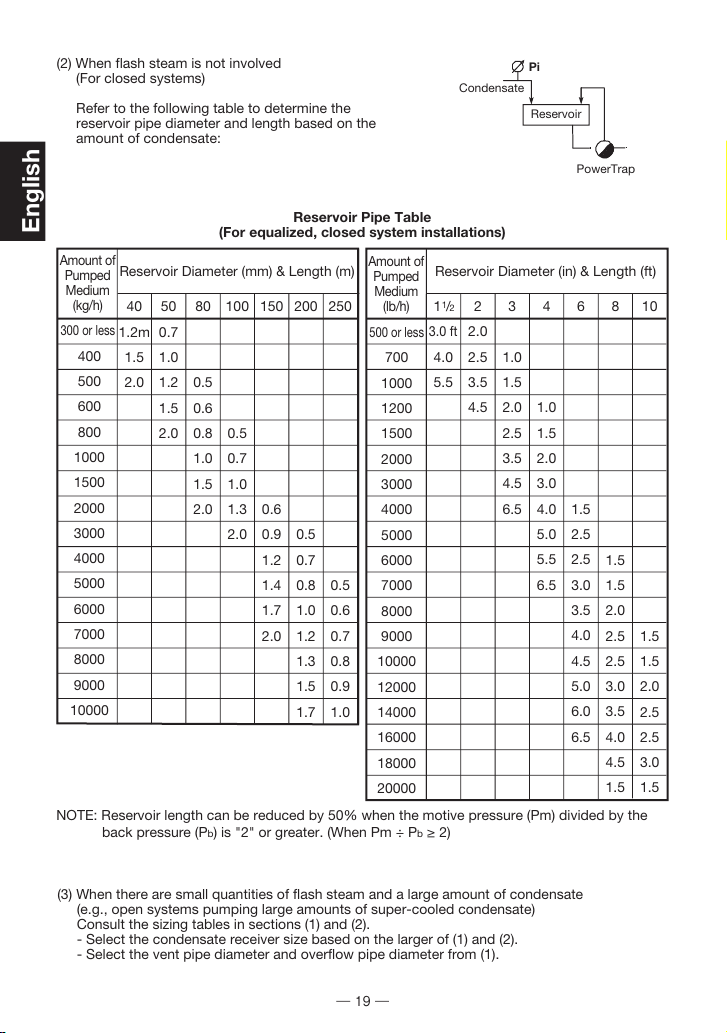
(2) When flash steam is not involved
(For closed systems)
Refer to the following table to determine the
reservoir pipe diameter and length based on the
amount of condensate:
300 or less
400
500
600
800
1000
1500
2000
3000
4000
5000
6000
7000
8000
9000
10000
Reservoir Diameter (mm) & Length (m)
Reservoir Diameter (in) & Length (ft)
500 or less
700
1000
1200
1500
2000
3000
4000
5000
6000
7000
8000
9000
10000
12000
14000
16000
18000
20000
40
1.2m
1.5
2.0
50
0.7
1.0
1.2
1.5
2.0
80
0.5
0.6
0.8
1.0
1.5
2.0
100
0.5
0.7
1.0
1.3
2.0
150
0.6
0.9
1.2
1.4
1.7
2.0
200
0.5
0.7
0.8
1.0
1.2
1.3
1.5
1.7
250
0.5
0.6
0.7
0.8
0.9
1.0
1
3.0 ft
4.0
5.5
2
2.0
2.5
3.5
4.5
3
1.0
1.5
2.0
2.5
3.5
4.5
6.5
4
1.0
1.5
2.0
3.0
4.0
5.0
5.5
6.5
6
1.5
2.5
2.5
3.0
3.5
4.0
4.5
5.0
6.0
6.5
8
1.5
1.5
2.0
2.5
2.5
3.0
3.5
4.0
4.5
1.5
10
1.5
1.5
2.0
2.5
2.5
3.0
1.5
NOTE: Reservoir length can be reduced by 50% when the motive pressure (Pm) divided by the
back pressure (Pb) is "2" or greater. (When Pm ÷ Pb≥2)
(3) When there are small quantities of flash steam and a large amount of condensate
(e.g., open systems pumping large amounts of super-cooled condensate)
Consult the sizing tables in sections (1) and (2).
- Select the condensate receiver size based on the larger of (1) and (2).
- Select the vent pipe diameter and overflow pipe diameter from (1).
Reservoir Pipe Table
(For equalized, closed system installations)
/
12
Amount of
Pumped
Medium
(kg/h)
Amount of
Pumped
Medium
(lb/h)
PowerTrap
Reservoir
Pi
Condensate
19
English
Other manuals for PowerTrap GP10L
1
This manual suits for next models
5
Table of contents
Languages:
Other TLV Water Pump manuals


Popular Water Pump manuals by other brands

EBARA
EBARA Ego B Operating and maintenance manual

morse
morse 26 Operator's manual

Grundfos
Grundfos Unilift AP12 Installation and operating instructions

Waukesha
Waukesha 200 series Operation and maintenance manual

Kärcher
Kärcher GP 60 MOBILE CONTROL Original instructions

Walrus Pump
Walrus Pump TQCN200 instruction manual


