TLV PowerTrap GT5C User manual

172-65473MA-03 (GT5C PowerTrap) 17 July 2019
GT5C
Copyright © 2019 by TLV CO., LTD.
All rights reserved

172-65473MA-03 (GT5C PowerTrap) 17 Jul 2019
1
Contents
Introduction......................................................................... 2
Safety Considerations........................................................ 3
General Description............................................................ 5
Application................................................................................................................5
Operation............................................................................ 6
Specifications..................................................................... 7
Configuration...................................................................... 8
Installation.......................................................................... 9
Steam System Example ...........................................................................................9
Installation Procedure.............................................................................................11
Sizing the Condensate Reservoir Pipe ...................................................................13
Maintenance Space and Tolerance Angle for Installation 14
Operation and Periodic Inspection................................... 15
Operation................................................................................................................15
Periodic Inspection and Diagnosis..........................................................................16
Disassembly/Reassembly................................................ 17
Recommended Tools List for Disassembly/Reassembly ........................................18
1. Before Removing/Reattaching............................................................................19
2. Removing/Reattaching the Body from / to the Cover..........................................20
3. Removing/Reattaching the Snap Action Unit......................................................20
4. Removing/Reattaching Each Unit.......................................................................22
5. Removing/Reattaching of Air Vent Unit...............................................................23
6. Positioning Adjustment of the Trap Valve...........................................................24
Troubleshooting................................................................ 25
Determining the Problem from the Symptoms........................................................25
Types of Failure and their Causes..........................................................................26
Causes and Corrective Measures...........................................................................27
Replacement Parts........................................................... 30
Product Warranty ............................................................. 31
Service ............................................................................. 32

172-65473MA-03 (GT5C PowerTrap) 17 Jul 2019
2
Introduction
Thank you for purchasing theTLV PowerTrap.
This product has been thoroughly inspected before being shipped from the
factory. When the product is delivered, before doing anything else, check the
specifications and external appearance to make sure nothing is out of the
ordinary. Also, be sure to read this manual carefully before use and follow the
instructions to be sure of using the product properly.
If detailed instructions for special order specifications or options not contained in
this manual are required, please contact TLV for full details.
This instruction manual is intended for use with the model listed on the front
cover. It is necessary not only for installation, but for subsequent maintenance,
disassembly/reassembly and troubleshooting. Please keep it in a safe place for
future reference.

172-65473MA-03 (GT5C PowerTrap) 17 Jul 2019
3
Safety Considerations
Read this section carefully before use and be sure to follow the instructions.
Installation, inspection, maintenance, repairs, disassembly, adjustment and valve
opening/closing should be carried out only by trained maintenance personnel.
The precautions listed in this manual are designed to ensure safety and prevent
equipment damage and personal injury. For situations that may occur as a result of
erroneous handling, three different types of cautionary items are used to indicate the
degree of urgency and the scale of potential damage and danger: DANGER,
WARNING and CAUTION.
The three types of cautionary items above are very important for safety: be sure to
observe all of them as they relate to installation, use, maintenance and repair.
Furthermore, TLV accepts no responsibility for any accidents or damage occurring
as a result of failure to observe these precautions.
Symbols
Indicates a DANGER, WARNING or CAUTION item.
DANGER
Indicates an urgent situation which poses a threat of death or serious
injury
WARNING
Indicates that there is a potential threat of death or serious injury
CAUTION
Indicates that there is a possibility of injury or equipment / product
damage
WARNING
NEVER apply direct heat to the float.
The float may explode due to increased internal pressure, causing
accidents leading to serious injury or damage to property and
equipment.
CAUTION
Install properly and DO NOT use this product outside the
recommended operating pressure, temperature and other
specification ranges.
Improper use may result in such hazards as damage to the product
or malfunctions that may lead to serious accidents. Local regulations
may restrict the use of this product to below the conditions quoted.
Use hoisting equipment for heavy objects (weighing
approximately 20 kg (44 lb) or more).
Failure to do so may result in back strain or other injury if the object
should fall.
Take measures to prevent people from coming into direct
contact with product outlets.
Failure to do so may result in burns or other injury from the discharge
of fluids.
When disassembling or removing the product, wait until the
internal pressure equals atmospheric pressure and the surface
of the product has cooled to room temperature.
Disassembling or removing the product when it is hot or under
pressure may lead to discharge of fluids, causing burns, other injuries
or damage.
Continued on next page

172-65473MA-03 (GT5C PowerTrap) 17 Jul 2019
4
CAUTION
Be sure to use only the recommended components when
repairing the product, and NEVER attempt to modify the product
in any way.
Failure to observe these precautions may result in damage to the
product and burns or other injury due to malfunction or the discharge
of fluids.
Do not use excessive force when connecting threaded pipes to
the product.
Over-tightening may cause breakage leading to fluid discharge, which
may cause burns or other injury.
Use only under conditions in which no freeze-up will occur.
Freezing may damage the product, leading to fluid discharge, which
may cause burns or other injury.
Use only under conditions in which no water hammer will occur.
The impact of water hammer may damage the product, leading to fluid
discharge, which may cause burns or other injury.
Take measures to ensure the proper handling, such as recovery
or dilution, of hazardous fluids discharged at product outlets.
Outflow of fluid or fluid leaks may lead to hazards such as flammable
conditions or corrosion, which may result in injury, fires, damage or
other accidents.

172-65473MA-03 (GT5C PowerTrap) 17 Jul 2019
5
General Description
Install properly and DO NOT use this product outside the recommended
operating pressure, temperature and other specification ranges. Improper
use may result in such hazards as damage to the product or malfunctions
which may lead to serious accidents. Local regulations may restrict the
use of this product to below the conditions quoted.
CAUTION
Application
PowerTrap GT5C can be used as a standard steam trap, and also has an integrated
pumping function that can eliminate and pump out condensate even if condensate
cannot be discharged due to very low supply steam pressure because of reduced load
in the steam using equipment (this phenomenon is referred to in this document as
‘stall’).
GT5C can also discharge the accumulated condensate when the steam using
equipment stops operation, and prevent water hammer when it re-starts operation.

172-65473MA-03 (GT5C PowerTrap) 17 Jul 2019
6
Operation
Take measures to prevent people from coming into direct contact with
product outlets. Failure to do so may result in burns or other injury from
the discharge of fluids.
CAUTION
(1) When condensate flows from the condensate inlet pipe through the inlet check valve
into the body of the unit, the float rises and the main valve of the trap unit is open as
shown in (A) below.
The main valve on the trap unit opens as the float rises. When Pi> Pb(when the
equipment pressure (Pi) is greater than the back pressure (Pb)), the condensate
passes through the outlet check valve and is discharged through the condensate
outlet pipe (normal trapping function).
In this case, the integrated air vent unit exhausts internal air to the outlet.
When Pi≤Pb, the condensate is not discharged and collects in the body of the
unit.
(2) When the float rises to its high level, the push rod on the snap-action unit rises
quickly, simultaneously closing the exhaust valve and opening the intake (motive
medium) valve. The pressure supplied by the motive medium causes the internal
pressure in the unit to become greater than the back pressure. The inlet check valve
closes and the outlet check valve is pushed open, thus discharging the condensate in
the unit through the outlet pipe, as shown in (B) below.
(3) As a result of the condensate in the unit being discharged, the water level in the unit
drops and the float descends. When the float reaches its low level, the push rod on
the snap-action unit moves down quickly, simultaneously opening the exhaust valve
and closing the intake (motive medium) valve and the status reverts to that shown in
(A) below.
Outlet Check Valve
Intake Valve [Open]
Exhaust Valve [Close]
Condensate Outlet
Pipe
Body
Exhaust Valve [Open]
Intake Valve [Close]
Operation Shaft
Cover
Trap unit
Float
Snap Action unit
Inlet Check Valve
Condensate Inlet Pipe
(A) Condensate Inflow (B) Condensate Discharge
(Exhaust) (Motive Medium Intake)
Air Vent Unit

172-65473MA-03 (GT5C PowerTrap) 17 Jul 2019
7
Specifications
Install properly and DO NOT use this product outside the recommended
operating pressure, temperature and other specification ranges.
Improper use may result in such hazards as damage to the product or
malfunctions which may lead to serious accidents. Local regulations
may restrict the use of this product to below the conditions quoted.
CAUTION
Use only under conditions in which no freeze-up will occur. Freezing
may damage the product, leading to fluid discharge, which may cause
burns or other injury.
CAUTION
Refer to the product nameplate for detailed specifications.
Valve No.**
Nominal Diameter
Model
Maximum Allowable
Pressure*
Maximum Allowable
Temperature*
Serial No.
Maximum Operating
Temperature
Maximum Differential
Pressure
* Maximum allowable pressure (PMA) and maximum allowable temperature (TMA) are PRESSURE SHELL
DESIGN CONDITIONS, NOT OPERATING CONDITIONS.
** Valve No. is displayed for products with options. This item is omitted from the nameplate when there are
no options.

172-65473MA-03 (GT5C PowerTrap) 17 Jul 2019
8
Configuration
Exhaust Outlet Plug
Motive Medium Inlet
Condensate Inlet
Condensate Outlet
N0.
Parts
Maintenance
Kit
Repair Kit *¹
Float
Snap
Action
Spring
A
B
C
D
E
1
Body
2
Cover
3
Gaskets, etc.
Gasket
✔
Seal set
✔
4
Cover Bolt
5
Nameplate
6
Float
✔
7
Snap-Action Unit
✔*²
8
Snap Action Spring
✔
9
Intake-Exhaust Valve Unit
✔
10
Trap Unit
✔
11
Air Vent Unit
✔
12
Inlet Check Valve
✔
13
(Flange)
14
Plug (for drainage)
Please refer to the replacement parts list for maintenance and repair kits.
*¹ The maintenance kit should be purchased along with a repair kit, as gaskets might be required.
*² A snap action spring is also contained in the snap-action unit.
172-65473MA-03 (GT5C PowerTrap) 17 Jul 2019
9
Installation
Install properly and DO NOT use this product outside the recommended
operating pressure, temperature and other specification ranges.
Improper use may result in such hazards as damage to the product or
malfunctions which may lead to serious accidents. Local regulations
may restrict the use of this product to below the conditions quoted.
CAUTION
Use hoisting equipment for heavy objects (weighing approximately
20 kg (44 lb) or more). Failure to do so may result in back strain or other
injury if the object should fall.
CAUTION
Take measures to prevent people from coming into direct contact with
product outlets. Failure to do so may result in burns or other injury from
the discharge of fluids.
CAUTION
Do not use excessive force when connecting threaded pipes to the
product. Over-tightening may cause breakage leading to fluid
discharge, which may cause burns or other injury.
CAUTION
Use only under conditions in which no water hammer will occur. The
impact of water hammer may damage the product, leading to fluid
discharge, which may cause burns or other injury.
CAUTION
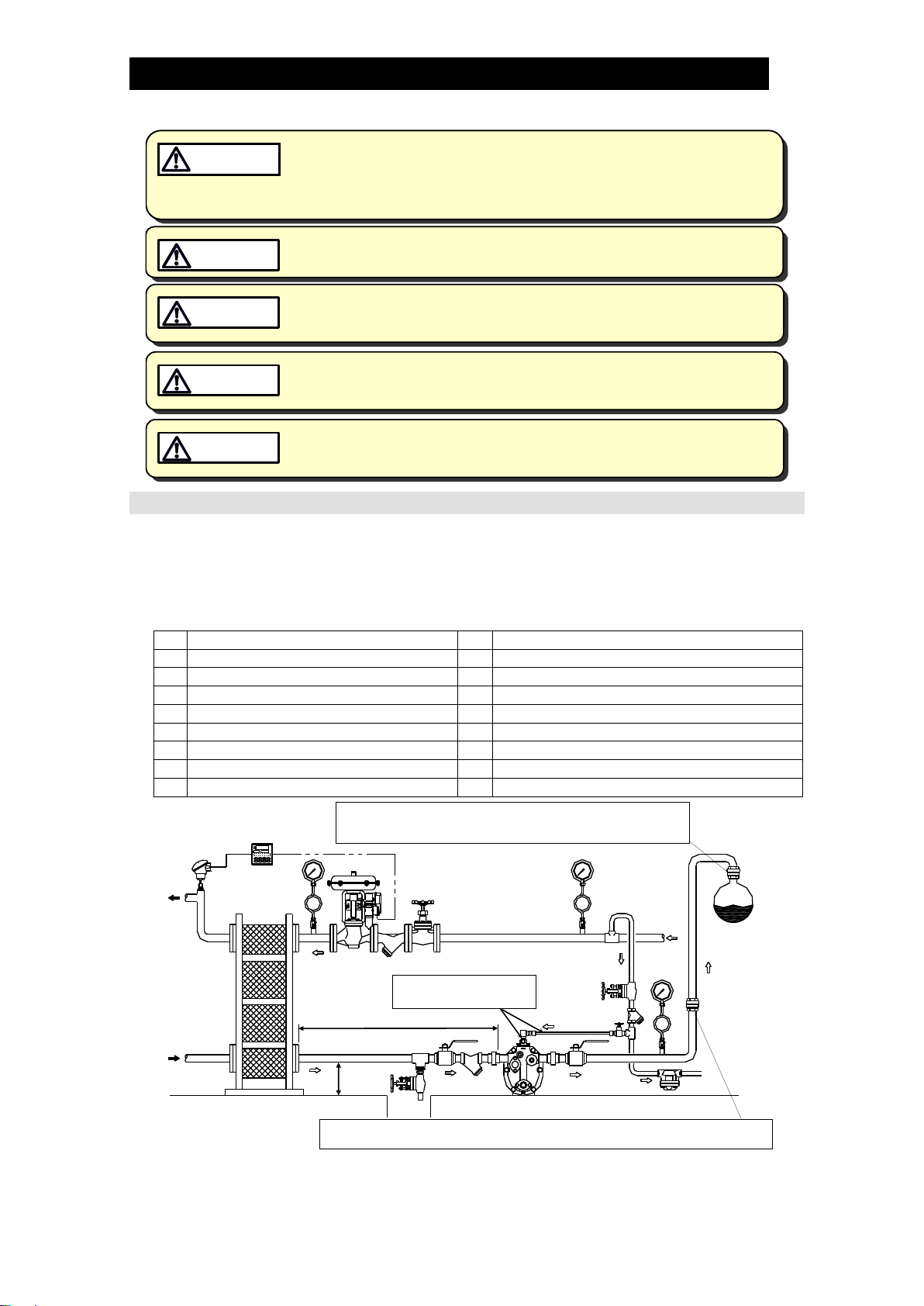
Steam System Example
For non-standard options, please refer to the additional instruction manual(s) provided.
1. Standard Installation Example
The example below shows the inlet piping is connected to the inlet of GT5C in the
same way as a standard steam trap. The condensate inlet pipe [Si] acts like a
condensate reservoir. Refer to “Sizing the Condensate Reservoir Pipe”at the end of
this section for the size of condensate inlet pipe [Si] (length of Dh).
Q
Pumped medium
Dh
Condensate Receiver/Reservoir
A
Filling Head
Ki
Condensate Inlet Strainer
Pm
Motive Medium Supply Pressure
Km
Motive Medium Strainer
Pb
Back Pressure
St
Steam Trap
Si
Condensate Inlet Pipe
Vi
Valve on Condensate Inlet Pipe
So
Condensate Outlet Pipe
Vo
Valve on Condensate Outlet Pipe
Sr
Condensate Recovery Line
Vm
Valve on Motive Medium Supply Pipe
Sm1
Motive Medium Supply Pipe
Vb
Blowdown Valve
Sm2
Motive Medium Supply Tube
Pi
Equipment Pressure
PowerTrap
Pm
Sr So
Pb
Sm1
Vm
Km
Vo
St
Sr
Si
QVb
Vi
Ki
A
Dh
Pi
Sm2
Backflow
Water Hammer
Prevention
Check Valve
If water hammer due to steam backflow in the condensate
recovery line is expected, installation of a check valve vertically
and as close as possible to the recovery line is recommended.
When the rise in piping is 30 m (100 ft) or farther from the PowerTrap, installation
of a check valve is recommended for the prevention of return water hammer.
Inner diameter should be
at least 8 mm (5/16 in)
Backflow
Water Hammer
Prevention
Check Valve
*Refer to diagrams shown in “Installation Procedure”and “(4)Inlet and Outlet Piping”in this section for the
length of condensate reservoir (Dh) in cases where the exhaust pipe is eliminated and there is vertical piping
on the pumped medium inlet due to elevated position ofthe equipment condensate outlet.

172-65473MA-03 (GT5C PowerTrap) 17 Jul 2019
10
2. Installation Example for Increasing Pump Discharge Capacity
The pumping discharge capacity can be increased by raising the filling head [A].
Refer to the latest GT5C data sheet for the discharge capacity on each filling head
and “Sizing of the Condensate Reservoir Pipe”at the end of this section for the size
of condensate inlet pipe [Si] (length of Dh).
Q
Condensate Supply
Dh
Condensate Reservoir
A
Filling Head
Ki
Condensate Inlet Strainer
Pm
Motive Medium Supply Pressure
Km
Motive Medium Strainer
Pb
Back Pressure
St
Steam Trap
Si
Condensate Inlet Pipe
Vi
Valve on Condensate Inlet Pipe
So
Condensate Outlet Pipe
Vo
Valve on Condensate Outlet Pipe
Sr
Condensate Recovery Line
Vm
Valve on Motive Medium Supply Pipe
Sm1
Motive Medium Supply Pipe
Ve
Valve on Exhaust Pipe
Se
Exhaust Pipe/Tube
Vb
Blowdown Valve
Sm2
Motive Medium Supply Tube
Pi
Equipment Pressure
A
Pm
Pi
PowerTrap
So
Pb
Sm1
Vm
Km
Vo
St
Sr
Si
Q
Vb
Vi
Ki
Dh
Sm2
Backflow
Water Hammer
Prevention
Check Valve
If water hammer due to steam backflow in the condensate
recovery line is expected, installation of a check valve vertically
and as close as possible to the recovery line is recommended.
When the rise in piping is 30 m (100 ft) or farther from the PowerTrap, installation
of a check valve is recommended for the prevention of return water hammer.
Backflow
Water Hammer
Prevention
Check Valve
Inner diameter should be
at least 8 mm (5/16 in)
In the above case, exhaust pipe [Se] should be connected from exhaust outlet to the
top of condensate inlet pipe [Si] (= condensate reservoir [Dh]).
The exhaust pipe [Se] should be 10 mm (3/8”) or a tube with an inner diameter of at
least 8 mm (5/16”). Insert the supplied fitting tube into the exhaust port after taking the
exhaust outlet plug out, and then attach the pipe to the GT5C. The discharge capacity
will not be increased effectively if the fitting tube is not installed properly.
Point the split ends upward, and
then insert while squeezing
Squeeze the fitting tube
while inserting
Insert the fitting tube, and then
connect to the port
Exhaust port
Fitting tube
172-65473MA-03 (GT5C PowerTrap) 17 Jul 2019
11
Installation Procedure
Installation, inspection, maintenance, repairs, disassembly, adjustment and valve
opening/closing should be carried out only by trained maintenance personnel.
(1) Pumped Medium:
Fluids that can be discharged through the PowerTrap are limited to steam
condensate. PowerTraps that have been specially constructed for other specific
fluids are not limited by this restriction.
(2) Motive Medium Supply Pipe [Sm1] and Motive Medium Supply Tube [Sm2]:
The motive medium supply pipe [Sm1] and valve on motive medium supply pipe
[Vm] diameter should be at least 15 mm (1/2”). If copper or stainless steel tubes are
used for the connection from the motive medium supply pipe [Sm1] to the
PowerTrap, make sure that the tube’s inner diameter is at least 8 mm (5/16”) but no
more than 3 m (10’) in length.
The inner diameter of the valve and tube fittings connecting to the PowerTrap
should also be at least 8 mm (5/16”).
Install a strainer [Km] (at least 15 mm (1/2in) and at least 40-mesh) on the
PowerTrap motive medium supply pipe [Sm1] as close to the PowerTrap as
possible and install a union joint for maintenance, while allowing sufficient space
for maintenance of the strainer. Strainers should be angled in the 3 or 9 o’clock
positions for horizontal installations.
Only use steam as the motive medium.
The maximum motive medium supply pressure is 0.5 MPaG (75 psig, 5 barg).
Install a drip leg on the motive medium supply pipe [Sm1], and a steam trap [ST] on
the drip leg.
Proper discharge capacity may not be achieved if condensate accumulates in the
motive medium supply pipe [Sm1] or tube [Sm2]. In addition, rust and scale cause
steam leakage, which results in the PowerTrap becoming inoperable.
Make sure to use steel pipe for the motive medium supply tube [Sm2].
Motive Medium Supply Tube
(No condensate accumulates)
Motive Medium Supply Pipe [Sm]
Correct
Steam Trap [ST]
Incorrect
Motive Medium Supply Tube
(Condensate accumulates)
Incorrect
Motive Medium Supply Tube
(Condensate accumulates)

172-65473MA-03 (GT5C PowerTrap) 17 Jul 2019
12
(3) Pressure Reducing Valve on the Motive Medium Supply Piping:
When the motive medium pressure [Pm] is greater than 0.5 MPaG (75 psig, 5
barg), install a TLV pressure reducing valve (such as the DR20) in order to reduce
the motive medium pressure to the PowerTrap. In order to prevent the pressure
from rising at dead end shut off, be sure to install a relief valve between the
pressure reducing valve and the PowerTrap.
The pressure setting on the pressure reducing valve should be between 0.05 and
0.15 MPa (7 and 20 psi, 0.5 and 1.5 bar) higher than the back pressure [Pb].
When the pumping capacity of the PowerTrap is insufficient for the set motive
pressure, increase this set pressure even further.
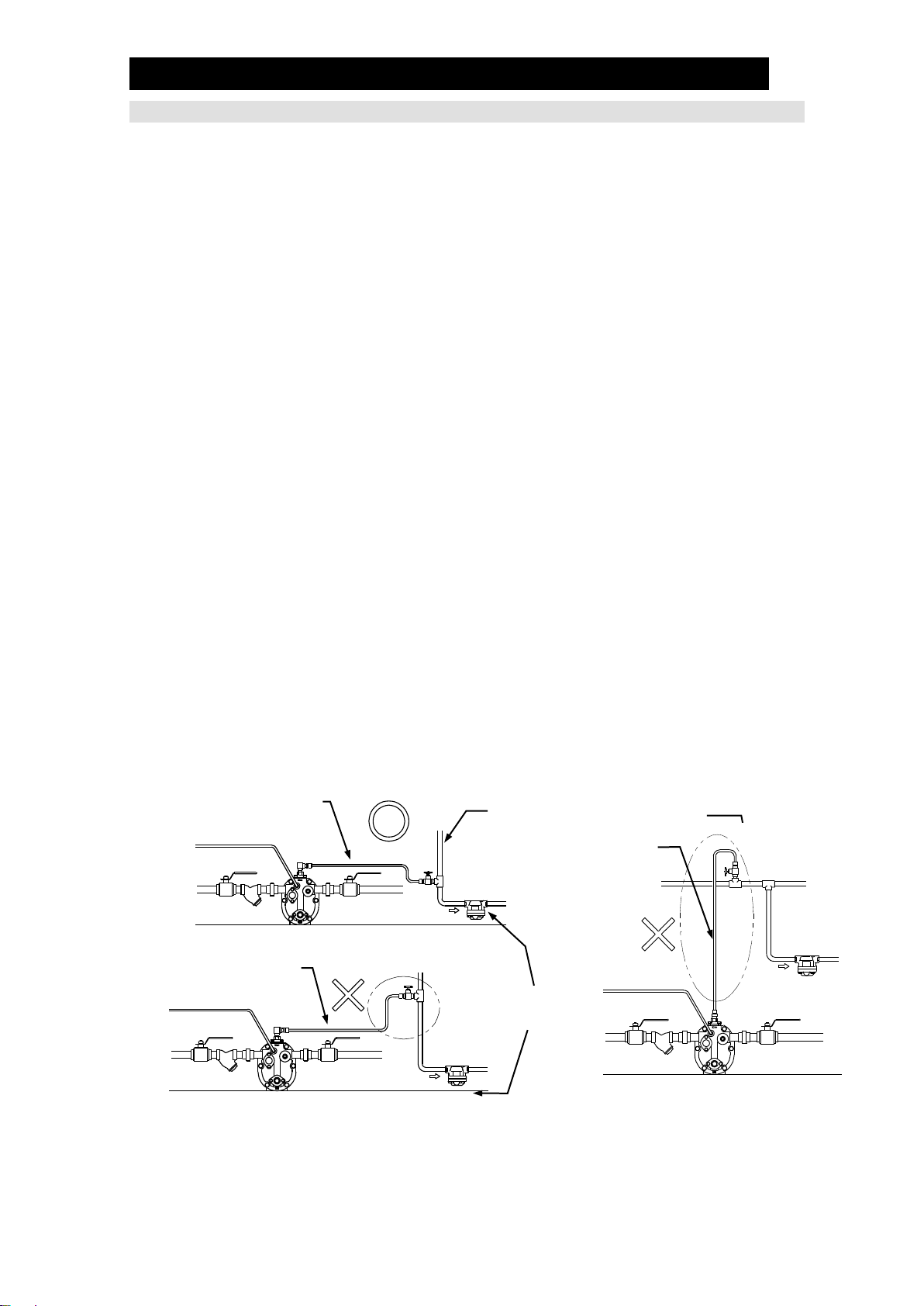
(4) Inlet and Outlet Piping
Install condensate inlet pipe [Si] to help
condensate flow into the PowerTrap by
gravity. Even if the exhaust tube is not
used (see drawing to the right), use a tee
so that the exhaust tube can be
connected when needed. The pipe
thickness should be schedule 40 or less
for proper operation.
Install a condensate inlet strainer [Ki] (40-mesh or finer) on the PowerTrap pumped
medium inlet pipe and install a union joint for maintenance. The installation should
be in a location that allows sufficient space for maintenance of the strainer [Ki].
Condensate outlet pipe [So] diameter should be at least 25 mm (1”).
Refer to “Sizing the Condensate Reservoir Pipe”at the end of this section for the
size of condensate inlet pipe [Si] (length of Dh).
During pumping operation, the PowerTrap uses the motive medium supply
pressure to push out the condensate in the trap. The GT5C can discharge
approximately 1.4 liters (3/8US Gallons) of pumped medium for each discharge
operation. The amount of time required for each discharge operation will be
between 5 and 30 seconds, depending on the back pressure and the motive
medium pressure. This means that the instantaneous flow through the condensate
outlet pipe [So] during the discharge operation is between 170 kg (370 lb) and 1
metric ton (2200 lb) per hour.
Flow meters must not be installed on the condensate outlet pipe [So]. Install a
steam flow meter at the equipment inlet if necessary.
Tee with Plug
Correct
Correct
Incorrect
Incorrect
Dh
Si
Filling head [A]
172-65473MA-03 (GT5C PowerTrap) 17 Jul 2019
13
(5) Valves on the Various Pipes
In order to ensure the proper discharge capacity, use full bore ball valves or gate
valves on the pumped medium inlet [Vi] and outlet lines [Vo].
Be sure to install blowdown valve [Vb]. A bellows sealed valve is recommended,
due to the lack of leakage from the gland and easy flow rate adjustment.
Install union or flanged joints between the valves and the PowerTrap to allow for
easy maintenance.
Be sure to provide the necessary maintenance space for PowerTrap disassembly
and repair (see “Maintenance Space”).
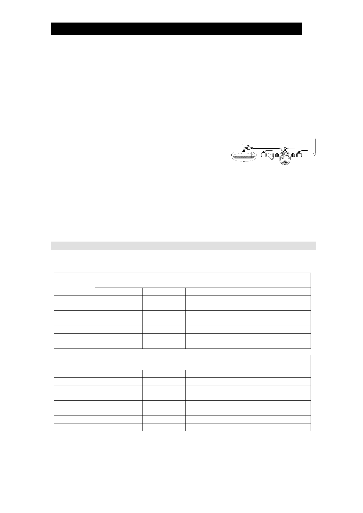
(6) Reservoir Pipe and Filling Head [A]
Please refer to “Size of the Condensate Reservoir
Pipe” shown below.
The size and length (volume) are determined by
the amount of pumped medium held back while
the PowerTrap is discharging. Therefore, the area
belowthe inlet piping cannot be considered in the
effective volume of the reservoir [Dh].
The filling head [A] represents the distance from the installation surface of the
PowerTrap (from grade) to the bottom of the inlet piping (condensate reservoir
[Si]), shown as [A] in the sketches in “Steam System Example”. The minimum
filling head for GT5C is 155 mm (6”).
Sizing the Condensate Reservoir Pipe
The PowerTrap reservoir pipe size for each condensate discharge amount should be
selected from the following table.
Condensate
Amount
kg/h
Diameter [mm (in)] and Length [m] of
Condensate Reservoir Pipe
25 (1)
32 (1¼)
40 (1½)
50 (2)
80 (3)
50
0.6 (m)
100
1.2
0.6
0.4
150
1.8
1.0
0.6
0.4
200
2.4
1.3
0.8
0.5
300
2.0
1.2
0.7
400
2.6
1.5
1.0
500
2.0
1.2
0.5
Condensate
Amount
lb/h
Diameter [in] and Length [ft] of
Condensate Reservoir Pipe
1”
1¼”
1½”
2”
3”
100
2.0 (ft)
150
3.0
1.5
200
3.9
2.0
1.3
300
5.6
3.0
2.0
1.3
500
4.9
3.0
2.0
700
6.9
4.0
2.5
1.0
1000
5.5
3.5
1.5
If the motive medium supply pressure [Pm]/back pressure (Pb) ≥2, the length of
condensate reservoir pipe can be reduced by ½.
Shadowed area is not included in
reservoir volume calculations

172-65473MA-03 (GT5C PowerTrap) 17 Jul 2019
14
Maintenance Space and Tolerance Angle for Installation
Maintenance Space
The maintenance space shown in the figure below should be provided to enable
inspection and disassembly/repair of the PowerTrap.
Tolerance Angle for Installation
The product should be inclined no more than 3°. Make sure the body is installed with the
raised TLV lettering on the body horizontal.
Unit: mm (in)
100 (4)
100 (4)
100 (4)

172-65473MA-03 (GT5C PowerTrap) 17 Jul 2019
15
Operation and Periodic Inspection
After all piping work has been completed in accordance with the
specific piping system designed when the decision to utilize the
PowerTrap was made, check once again to make sure that all pipe
connections have been tightened, gaskets have been inserted where
needed and all parts are securely installed.
At the start-up of operation, large quantities of condensate may flow,
causing the PowerTrap to momentarily overload. Open the inlet valve
gradually so that the condensate flows in slowly.
WARNING
Install properly and DO NOT use this product outside the recommended
operating pressure, temperature and other specification ranges.
Improper use may result in such hazards as damage to the product or
malfunctions which may lead to serious accidents. Local regulations
may restrict the use of this product to below the conditions quoted.
CAUTION
When disassembling or removing the product, wait until the internal
pressure equals atmospheric pressure and the surface of the product
has cooled to room temperature. Disassembling or removing the
product when it is hot or under pressure may lead to discharge of fluids,
causing burns, other injuries or damage.
CAUTION
Be sure to use only the recommended components when repairing the
product, and NEVER attempt to modify the product in any way. Failure to
observe these precautions may result in damage to the product or burns
or other injury due to malfunction or the discharge of fluids.
CAUTION
Installation, inspection, maintenance, repairs, disassembly, adjustment and valve
opening/closing should be carried out only by trained maintenance personnel.
Operation
(1) Valve Operation
During the first operation after installation, or re-operation after a long shutdown,
open blowdown valve [Vb] (ensuring that the area around the opening is safe) to
eliminate rust and scale completely. Refer to the “Steam System Example”drawings
in the “Installation”section to become familiar with the symbols used for the various
valves.
If water hammer has occurred, immediately cease operation and close any valves
that are operating.
a) Slowly open the valve [Ve] on the exhaust pipe.
b) Slowlyopen the valve [Vm] on the motive medium supply pipe. Make sure that there
is no sound of flow from the exhaust pipe [Se] or the condensate inlet pipe [Si].
c) Slowly open the valve [Vo] on the pumped medium outlet pipe.
d) Slowly open the valve [Vi] on the pumped medium inlet pipe.
e) During normal trapping operation (equipment side pressure > back pressure), the
GT5C discharges condensate continuously. During stall or reverse pressure
(equipment side pressure ≤ back pressure), the GT5C switches to pumping
operation. The PowerTrap is normal if it operates intermittently during pumping
operation; first exhausting the motive medium to fill with pumped medium, then
taking in motive medium to force the condensate out.
The interval of operation will vary greatly depending on the amount of pumped
medium inflow, the temperature, the motive medium (steam) pressure. (The
interval of operation is considered the length of time between the start of one
discharge cycle and the start of the next discharge cycle.)

172-65473MA-03 (GT5C PowerTrap) 17 Jul 2019
16
The relation between the interval of operation Tc(seconds) and the amount of
inflowing pumped medium (Q or Qp) can be roughly determined using the
following formula:
Tc= 5,000/Q Q = 5,000/TcQ: amount of inflowing pumped medium (kg/h)
Tc= 11,111/Qp Qp= 11,111/TcQp: amount of inflowing pumped medium (lb/h)
(2) If an error such as a leak or water hammer occurs after beginning PowerTrap
operation, shut off the valves immediately in the following order:
valve [Vm] on motive medium supply pipe pumped medium inlet valve [Vi]
pumped medium outlet valve [Vo] valve [Ve] on exhaust pipe
(3) Whenever any type of malfunction is suspected in the PowerTrap, refer to the
“Troubleshooting” section.
Periodic Inspection and Diagnosis
There are two types of periodic inspection: the visual inspection and the disassembly
inspection.
(1) Visual Inspection
As a general rule, this inspection should be performed at least once every 3
months.
Check the following items:
a) There should be no leakage from the PowerTrap or from any of the connections.
b) The PowerTrap unit should make continuous sound during trapping operation
(equipment side pressure > back pressure).
c) The PowerTrap unit should be operating cyclically without continuous sound in
the motive medium supply pipe or the exhaust pipe during the pumping
operation (equipment side pressure ≤ back pressure).
d) Pumped medium should not accumulate in the (steam-using) equipment, and
the temperature of the equipment should not be abnormally low.
e) There should not be any abnormal noise (such as water hammer) from the
pumped medium outlet pipe or the pumped medium recovery line when the
PowerTrap operates.
(2) Disassembly Inspection
Refer to the “Disassembly/Reassembly” section.
As a general rule, this inspection should be performed at least once every 2 years.
When inspecting the interior of the unit, check the following items:
a) Make sure the snap-action unit moves up and down smoothly as the float rises
and falls.
b) Make sure the valve of the trap unit moves up and down smoothly as it opens
and closes.
c) Make sure the intake/exhaust valves move up and down smoothly.
d) Make sure the float is not damaged and is not filled with water.
e) Make sure all nuts and bolts are properly installed and fastened.
f) Check to make sure that there is no foreign matter sticking to the shafts and
levers of any of the units, and make sure there is no abnormal wear.
When reassembling, be sure to replace the body and cover gaskets with new
gaskets if damaged.
Also, replace any parts that are broken or show serious wear.
If any parts require replacement, refer to the “Replacement Parts” List.

172-65473MA-03 (GT5C PowerTrap) 17 Jul 2019
17
Disassembly/Reassembly
NEVER apply direct heat to the float. The float may explode due to
increased internal pressure, causing accidents leading to serious injury
or damage to property and equipment.
WARNING
Use hoisting equipment for heavy objects (weighing approximately
20 kg (44 lb) or more). Failure to do so may result in back strain or other
injury if the object should fall.
CAUTION
When disassembling or removing the product, wait until the internal
pressure equals atmospheric pressure and the surface of the product
has cooled to room temperature. Disassembling or removing the
product when it is hot or under pressure may lead to discharge of fluids,
causing burns, other injuries or damage.
CAUTION
Do not use excessive force when connecting threaded pipes to the
product. Over-tightening may cause breakage leading to fluid
discharge, which may cause burns or other injury.
CAUTION
Use the procedures on the following pages to remove components. Use the same
procedures in reverse to reassemble. (Installation, inspection, maintenance, repairs,
disassembly, adjustment and valve opening/closing should be carried out only by trained
maintenance personnel.)
In cases where sufficient maintenance space has been provided for (see “Maintenance
Space”), maintenance can be carried out without disconnecting the inlet and outlet
piping. Where there is insufficient maintenance space, first disconnect the inlet and
outlet piping, and then move the unit to a spacious area in which maintenance can be
carried out safely.
When reassembling:
Also replace any gaskets, units or parts that are broken or show serious wear. If
any parts require replacement, refer to “Replacement Parts”.
When reassembling, coat threads and bolts with anti-seize. Tighten the body and
cover bolts in a uniform manner left and right, being careful to avoid uneven
tightening.
If drawings or other special documentation were supplied for the product, any
torque given there takes precedence over values shown here.

172-65473MA-03 (GT5C PowerTrap) 17 Jul 2019
18
Recommended Tools List for Disassembly/Reassembly
No.
Tool Name
Step Used
Tool
1
Torque Wrench (Ratchet)
0 –100 Nm
(0 –73 lbfft)
1,2,3,4,5,6
2
Sockets
Distance across flats = S
13 mm (½”)
19 mm (¾”)
22 mm (78")
3,4,6
2,5
4
S
3
Extension Bar
L = 150 mm (578")
5
4
Offset Wrench
13 mm (½”)
19 mm (¾”)
22 mm (78")
3,4,6
2
4
5
Adjustable Wrench
L=200 –300 mm
(8”–12”)
1, 6
6
Needle-Nose Pliers
3
7
Hex Key
2.5mm (332”)
6
8
Internal Snap Ring Pliers
4
(1 Nm 10 kgcm2)
L
S

172-65473MA-03 (GT5C PowerTrap) 17 Jul 2019
19
1. Before Removing/Reattaching
Discharge the condensate from the body before removing parts.
(1 Nm 10 kgcm2)
Part
Disassembly
Reassembly
Plug
•Discharging condensate is carried out with the intake
(motive medium), exhaust, inlet and outlet piping still
connected to the unit.
•Using an adjustable wrench, slowly loosen plug to release
pressure and discharge fluid. Take care to avoid being
burned by fluid discharge. (Opening this plug may help to
discharge condensate in the body more easily when the
drain plug is opened.)
• Wrap threads with 3
–3.5 turns of sealing
tape or apply sealing
compound.
• Tighten to a torque of
30 Nm (22 lbfft).
Drain Plug
•Using an adjustable wrench, slowly loosen plug to release
pressure and discharge fluid, take care to avoid being
burned by fluid discharge.
• Wrap threads with
3 –3.5 turns of
sealing tape or apply
sealing compound.
• Tighten to a torque of
30 Nm (22 lbfft).
Plug
Drain Plug
Other manuals for PowerTrap GT5C
1
Table of contents
Other TLV Water Pump manuals


Popular Water Pump manuals by other brands

Graco
Graco SaniForce 1590 HS Instructions-parts list

Pratissoli
Pratissoli MW Series Use and maintenance manual

Ingersoll-Rand
Ingersoll-Rand ARO PD10P Series Operator's manual

Kärcher
Kärcher BPE 4200/50 instructions

Alemlube
Alemlube O30060 instruction manual

Wilo
Wilo DrainLift M2/8 Installation and operating instructions


