TMC EPIC 810-ECA User manual

Please read before using feature module.
810-ECA
Model 810-ECA
External Cordless Adapter
User’s Guide
ECA for PDF v13 070903.qxd 7/9/2003 3:30 PM Page 2

i
Getting Started
Getting Started
Congratulations! You’ve purchased a TMC Model 810-ECA External Cordless
Adapter that meets the highest standards for quality and convenience in the
Small Office/Home Office environment. To get the most from your Feature
Module, please take time to read this guide thoroughly.
IMPORTANT SAFETY INSTRUCTIONS
When using your telephone equipment, basic safety precautions should always
be followed to reduce the risk of fire, electric shock and injury to persons, includ-
ing the following:
1.
2.
3.
4.
5.
SAVE THESE INSTRUCTIONS
Do not use this product near water, for example, near a bath tub, wash bowl,
kitchen sink, or laundry tub, in a wet basement, or near a swimming pool.
Avoid using a telephone (other than a cordless type) during an electrical
storm. There may be a remote risk of electric shock from lightning.
Do not use the telephone to report a gas leak in the vicinity of the leak.
Use only the power cord and batteries indicated in this manual. Do not dis-
pose of batteries in a fire. They may explode. Check with local codes for pos-
sible special disposal instructions.
Use only the class 2 power adapter 12VDC 500 mA.
!
ECA for PDF v13 070903.qxd 7/9/2003 3:30 PM Page 3

The TMC Model 810-ECA External Cordless Adapter is designed for easy installation in your
home or office. However, it is important that you follow these few simple guidelines:
- Take a few minutes to read this manual so that you thoroughly understand the instructions to
be followed for proper installation of your Cordless Adapter.
- This User’s Guide provides easy to understand directions for operation of your Feature
Module. Please retain these instructions for future reference.
Packing List
Remove the unit from the package and check this list to be certain all parts are included:
ii
Before you begin . . .
To order any packing list items, call toll-free 1-800-TMC-1638.
Feature Module Two Telephone Line Cords
AC Adapter
Getting Started
ECA for PDF v13 070903.qxd 7/9/2003 3:30 PM Page 4

Getting Started . . . . . . . . . . . . . . . . . . . . . . . . . . . . . . . . . . . . . . . . . . . . . .i
Reference Drawing . . . . . . . . . . . . . . . . . . . . . . . . . . . . . . . . . . . . . . . . . . .v
Section 1 - Installing Your External Cordless Adapter . . . . . . . . . . . . . .1-6
Step 1: Connect Line Cords . . . . . . . . . . . . . . . . . . . . . . . . . . . . . . .2
Step 2: Connect Telephone to Adapter . . . . . . . . . . . . . . . . . . . . . . .3
Step 3: Set Left DIP Switches to Proper Postions . . . . . . . . . . . . . .4
Step 4: Set Right DIP Switches to Proper Postions . . . . . . . . . . . . .5
Step 5: Connect Power Cord . . . . . . . . . . . . . . . . . . . . . . . . . . . . . .6
Section 2 - Using Your External Cordless Adapter . . . . . . . . . . . . . . . .7-15
Capabilities of your External Cordless Adapter . . . . . . . . . . . . . . . . .8
Important Points to Note . . . . . . . . . . . . . . . . . . . . . . . . . . . . . . . . . .9
Making a Call . . . . . . . . . . . . . . . . . . . . . . . . . . . . . . . . . . . . . . . . . .10
Answering a Call . . . . . . . . . . . . . . . . . . . . . . . . . . . . . . . . . . . . . . . .11
Using the Flash Button . . . . . . . . . . . . . . . . . . . . . . . . . . . . . . . . . . .12
Conferencing Two Outside Lines . . . . . . . . . . . . . . . . . . . . . . . . . . .13
Making and Answering Intercom Calls . . . . . . . . . . . . . . . . . . . . . . .14
Making Pages . . . . . . . . . . . . . . . . . . . . . . . . . . . . . . . . . . . . . . . . . .15
Section 3 - Additional Information . . . . . . . . . . . . . . . . . . . . . . . . . . . . . .17-21
Troubleshooting Guide . . . . . . . . . . . . . . . . . . . . . . . . . . . . . . . . . . .18
Warranty Information . . . . . . . . . . . . . . . . . . . . . . . . . . . . . . . . . . . . .19
FCC Information . . . . . . . . . . . . . . . . . . . . . . . . . . . . . . . . . . . . . . . .20
Table of Contents
iv
ECA for PDF v13 070903.qxd 7/9/2003 3:30 PM Page 6

Reference Drawing
v
Strain Relief Tab
Jacks for connection
to Wall
Jacks for connection to a
Phone
IMPORTANT NOTE:
These two jacks are
designed to allow you to
share your feature module
with another phone, such
as a TMC ET4000.
These jacks ARE NOT for
connection to the cordless
phone.
Please connect the base of
your single-line cordless
phone into the jack labeled
“TO CORDLESS PHONE.”
Jack for connection to a
Cordless Phone
Status Indicator Lamp
Left Dip Switches
Right Dip Switches
AC Adapter Jack
ECA for PDF v13 070903.qxd 7/9/2003 3:30 PM Page 7

Installing Your External Cordless Adapter
Section
1
Installing
Your
External
Cordless
Adapter
1
Page
2 Step 1: Connect Line Cords
3 Step 2: Connect Telephone to
Adapter
4 Step 3: Set Left DIP Switches
to Proper Positions
5 Step 4: Set Right DIP Switches
to Proper Positions
6 Step 5: Connect Power Cord
ECA for PDF v13 070903.qxd 7/9/2003 3:30 PM Page 8

Step 1: Connect Line Cords
1 Connect First Line Cord
Connect one end of a long telephone line cord
to the jack on the back of the feature module
labeled L1/L2. Connect the other end to the
jack(s) labeled Lines 1 & 2 either:
directly to the wall jack if it is a two-line RJ14
jack
OR
to a two-line coupler (not provided) if you have
two single-line RJ11 jacks for lines 1 and 2.
Then connect the two cords of the coupler to
the corresponding wall jacks. Two-line cou-
plers are available many places, for example
Radio Shack (part #279-401).
2 Connect Second Line Cord
Connect one end of a long telephone line cord
to the jack on the back of the feature module
labeled L3/L4. Connect the other end to the
jack(s) labeled Lines 3 & 4 in the same manner
as described in the previous step.
NOTE: If you wish to plug in the module to a
jack that is already in use, unplug the existing
device from the wall jacks, connect both of the
line cords to the module as shown, and then
plug the device into the jacks on the module
labeled “TO PHONE.”
2
Installing Your External Cordless Adapter
L3/L4
L1/L2
Line 1 Line 2
L1/L2
Lines
1&2
ECA for PDF v13 070903.qxd 7/9/2003 3:30 PM Page 9

Installing Your Cordless Phone Adapter
Step 2: Connect Telephone to Adapter
3
1 Install Cordless Telephone
Please follow the installation instructions that
came with your cordless telephone.
Note that TMC Corporation does not manufac-
ture cordless telephones. The Cordless Phone
Adapter has been designed to be compatible
with any standard single-line telephone.
2 Connect Cordless Phone Base to
Adapter
Connect one end of the telephone line cord
that came with your cordless phone to the jack
in the cordless phone base as instructed in the
installation instructions that came with your
cordless phone, and plug the other end into the
jack on the External Cordless Adapter labeled
“To Cordless Phone.”
Note that you can use any single line device
with your Cordless Phone Adapter; it need not
be a cordless telephone. It is called a “External
Cordless Adapter” because most people use it
to provide a cordless extension for their
System.
Plug line cord
from telephone
to this jack on
the rear of the
feature module
ECA for PDF v13 070903.qxd 7/9/2003 3:30 PM Page 10

Installing Your External Cordless Adapter
Step 3: Set LeftDIP Switches to Proper Positions
Set Switches 1-2
The setting of these two DIP switches
determines the ringer setting for line 1.
Please refer to the drawing at the right to
determine how to set the DIP switches for
line 1.
Set Switches 3-8
The setting of these six DIP switches
determines the line and ringer settings for
lines 2, 3, and 4.
Please refer to the drawing at right for
instructions on setting each line. Note that
the drawing illustrates setting DIP switch-
es 3-4 for setting line 2. Set DIP switches
5-6 in the same manner to set line 3, and
set DIP switches 7-8 in the same manner
to set line 4.
Ringer ON
Ringer OFF
Ringer ON
Ringer OFF
Line
UNCONNECTED
4
ECA for PDF v13 070903.qxd 7/9/2003 3:30 PM Page 11

Installing Your External Cordless Adapter
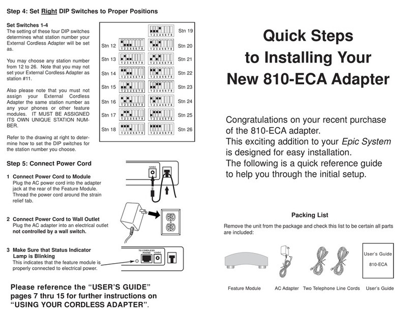
Step 4: Set Right DIP Switches to Proper Positions
Set Switches 1-4
The setting of these four DIP switches
determines what station number your
External Cordless Adapter will be set as.
You may choose any station number from
12 to 26. Note that you may not set your
External Cordless Adapter as station #11.
Also please note that you must not assign
your External Cordless Adapter the same
station number as any of your phones or
other feature modules. IT MUST BE
ASSIGNED ITS OWN UNIQUE STATION
NUMBER.
Refer to the drawing at right to determine
how to set the DIP switches for the station
number you choose.
Set Switch 5
The setting of this DIP switch determines
flash length.
Set the switch in the up position for normal
length flashes (approximately 700 mil-
liseconds), or place the switch in the down
position for short flashes (approximately
200 milliseconds).
In most environments it is best to leave
this switch in the up position, for normal
length flashes. If you find that calls are
dropping when you use the flash button,
then try setting the switch in the down
position.
Set switch 5 in the up position to set
this External Cordless Adapter to
normal length flashes
Set switch 5 in the down position to
set this External Cordless Adapter to
short flashes
Stn 12
Stn 13
Stn 14
Stn 15
Stn 16
Stn 17
Stn 18
Stn 19
Stn 20
Stn 21
Stn 22
Stn 23
Stn 24
Stn 25
Stn 26
5
ECA for PDF v13 070903.qxd 7/9/2003 3:30 PM Page 12

6
Step 5: Connect Power Cord
Installing Your Cordless Phone Adapter
1 Connect Power Cord to Module
Plug the AC power cord into the adapter jack at
the rear of the Feature Module. Thread the
power cord around the strain relief tab.
2 Connect Power Cord to Wall Outlet
Plug the AC adapter into an electrical outlet not
controlled by a wall switch.
3 Make Sure that Status Indicator Lamp
is Blinking
This indicates that the feature module is prop-
erly connected to electrical power.
ECA for PDF v13 070903.qxd 7/9/2003 3:30 PM Page 13

7
Using Your Cordless Phone Adapter
Section
2
Using Your
External
Cordless
Adapter
Page
8 Capabilities of your External
Cordless Adapter
9 Important Points to Note
10 Making a Call
11 Answering a Call
12 Using the Flash Button
13 Conferencing Two Outside
Lines
14 Making and Answering
Intercom Calls
15 Making Pages
ECA for PDF v13 070903.qxd 7/9/2003 3:30 PM Page 14

8
Using Your External Cordless Adapter
Capabilities of your Cordless Phone Adapter
Features of your External Cordless
Adapter
•Make Calls on Any Line
•Answer Calls on Any Line
•Place Calls on Hold
•Conference Two Outside Lines
•Make Intercom Calls
•Answer Intercom Calls
•Make Pages
•Make an Intercom Call or Page to
another Station while You Have a
Call on Hold
•Transfer a Call to Another Station
•Receive Calls Transferred from other
Stations
•If your cordless phone has a caller ID
display, it will indicate which line an
incoming call is ringing on.
•If you subscribe to caller ID and your
cordless phone has a caller ID dis-
play, it will display the caller ID infor-
mation
•If you are engaged in a call and a
call is ringing on another line, you will
hear one, two, three, or four beeps in
your ear to indicate which line the
call is coming in on.
You may connect up to 15 External Cordless
Adapters to your System. Connect each one to
a separate cordless telephone, and assign each
one a station number from 12 to 26 (See page
5).
Once you connect your cordless phone to the
External Cordless Adapter, you will enjoy all the
features listed on this page.
ECA for PDF v13 070903.qxd 7/9/2003 3:30 PM Page 15

Important Points to Note
Using Your External Cordless Adapter
9
You must attach your External Cordless Adapter to all lines that you wish to
access from your cordless telephone.
You must connect your External Cordless Adapter to line 1 for it to function.
This feature module is called a “External Cordless Adapter” because most peo-
ple use it to provide a cordless extension to their System. However, it works
with any standard single-line telephone.
You may connect up to 15 External Cordless Adapters to your System. Connect
each one to a separate cordless telephone and assign each one a different
extension number from 12 to 26.
Your External Cordless Adapter will not work with private lines.
The External Cordless Adapter is compatible with features such as call waiting,
Centrex, and other central office features that require the use of the Flash but-
ton. However, please remember that if you want to make a switchhook flash,
you must press the Flash button, followed by “0.”
ECA for PDF v13 070903.qxd 7/9/2003 3:30 PM Page 16

10
Using Your External Cordless Adapter
Making a Call
To make a call on any available line:
1Go off-hook with your telephone. With
most cordless phones, this is done by
the pressing of a button labeled “Phone”
or “On.” Note that you will now be
hearing the internal dial tone.
2Dial “9” on your telephone.
This will seize the first available line, and
you should now be hearing the regular
dial tone.
3Dial your call normally.
To make a call on a particular line:
1Go off-hook with your telephone. With
most cordless phones, this is done by
the pressing of a button labeled “Phone”
or “On.” Note that you will now be
hearing the internal dial tone.
2Dial “81”, “82”, “83” or “84” on your tele-
phone.
81 ...if you wish to seize line 1
82 ...if you wish to seize line 2
83 ...if you wish to seize line 3
84 ...if you wish to seize line 4
This will seize that particular line, and
you should now be hearing the regular
dial tone.
3Dial your call normally.
When you go off-hook at your cordless tele-
phone, you will hear the internal dial tone.
You may then select a line to make your outside
call.
To seize the first available line, dial “9” on your
telephone’s dialpad. You will be connected to
line 1, if it is free. If line 1 is in use, you will be
connected to line 2, and so on.
If, however, you wish to make an outgoing call
on a particular line, dial “8”, followed by the cor-
responding number on the dialpad. For exam-
ple, if you wish to make a call on line 3, dial “83”
on the dialpad. Note that if that particular line is
in use, you will not automatically be connected
to another line.
After you dial “9” or the particular number to
seize a line, you will hear the regular dial tone.
You may now dial your call in the normal manner.
Note: You can also use these steps to take a
call off of hold that has been put on hold by
another Station. Simply go off hook at your cord-
less phone (you should now be hearing the inter-
nal dial tone), and then dial “81” to take a call off
hold on line 1, or “82” to take a call off hold at line
2, and so on.
ECA for PDF v13 070903.qxd 7/9/2003 3:30 PM Page 17

11
Using Your External Cordless Adapter
Answering a Call
To answer a call that is ringing at your
cordless telephone:
1Go off-hook at your telephone. With
most cordless phones, this is done by
the pressing of a button labeled “Phone”
or “On.”
Note that this is exactly the same way
that you would answer a ringing call if
your cordless telephone were connected
directly to the line.
Note that if your cordless phone has
caller ID capability, the display will indi-
cate which line the call is ringing on. The
display will read “L1:”, “L2:”, “L3:”, or
“L4:” and will also display the caller ID
info if you subscribe to the caller ID ser-
vice on that line.
To answer a call that is not ringing at
your cordless telephone:
1Go off-hook at your telephone. With
most cordless phones, this is done by
the pressing of a button labeled “Phone”
or “On.” Note that you will now be
hearing the internal dial tone.
2Dial “81”, “82”, “83” or “84” on your tele-
phone.
81 ...if you wish to answer a call on line 1
82 ...if you wish to answer a call on line 2
83 ...if you wish to answer a call on line 3
84 ...if you wish to answer a call on line 4
This will seize that particular line, and
you should now be speaking to the call-
ing party.
When your cordless telephone is ringing, you
may answer the call by simply going off-hook at
that telephone. You will automatically be con-
nected to the ringing line.
You may however wish to turn some or all of your
ringers OFF at your cordless phone (See page 4
for instructions on doing this).
If you wish to answer a particular line that you
hear ringing at another phone, but whose ringer
is OFF at your cordless phone, do the following:
Go off-hook at your telephone. Note that you
will now be hearing the internal dial tone.
To answer the ringing line, dial “8”, followed by
the corresponding number on the dialpad of your
cordless telephone.
IMPORTANT NOTE: If you are engaged in a call
on your cordless phone, and a call is ringing on
another line, you will hear one, two, three, or four
beeps in your ear to indicate which line the call
is ringing on.
If you wish to answer that call, you may hang up
your cordless phone, wait for your cordless
phone to start ringing, then go off hook to answer
the new call.
Or you may put your current call on hold by
pressing FLASH, then dial “81”, “82”, “83” or “84”
to answer the ringing line. When you wish to
return to your call on hold, hang up your cordless
phone, wait for your cordless phone to start ring-
ing, then go off hook and you will be connected
to the original call.
ECA for PDF v13 070903.qxd 7/9/2003 3:30 PM Page 18

12
Using Your External Cordless Adapter
Using the Flash button
To put a call on hold:
1Press the FLASH button on your cordless
phone.
To take the call off of hold:
1Press the FLASH button on your cordless
phone again.
Note that you can also take the call off of
hold at any other phone by simply seiz-
ing that line at the other telephone.
To make a switchhook flash:
1Press the FLASH button on your cordless
phone.
2Dial “0.”
The Flash button is used for placing calls on
hold, taking calls off of hold, and conferencing
two lines together, as well as the standard Flash
function of causing a switchhook flash.
To put a call on hold, simply press the Flash but-
ton on your cordless phone.
You can take the call of from hold at any system
or non-system telephone by seizing the line at
that phone. If you would like to take the call of
from hold at your cordless phone, simply press
Flash again.
IMPORTANT: If you would like to use the Flash
button to make a switchhook flash, press the
Flash button and then dial “0.”
This feature is used to activate services such as
Call Waiting or 3-Way Calling, or certain Centrex
features or other features that may be offered by
your Telephone Company.
ECA for PDF v13 070903.qxd 7/9/2003 3:30 PM Page 19

13
Using Your External Cordless Adapter
Conferencing Two Outside Lines
To conference two outside lines:
1Place your first call on hold by pressing
FLASH. Note that you will now be
hearing the internal dial tone.
2Make or answer your second call. (See
pages 10 and 11, starting with step 2).
3Press FLASH again to conference the
two lines together.
4To end a conference call, hang up.
Both parties will be disconnected.
While having a conversation on one line, you
can make or answer a call on another line, then
connect both lines together to create a confer-
ence call.
To end the conference call, hang up your cord-
less phone and both parties will be disconnect-
ed.
ECA for PDF v13 070903.qxd 7/9/2003 3:30 PM Page 20

14
Making and Answering Intercom Calls
Using Your External Cordless Adapter
To intercom another station:
1Go off-hook with your telephone. With
most cordless phones, this is done by
the pressing of a button labeled “Phone”
or “On.” Note that you will now be
hearing the internal dial tone.
2Dial “*”, followed by a number from 11-
26, indicating the station you wish to
intercom.
3After someone answers or you hear the
confirming tone, speak towards the tele-
phone and talk.
4To end the conversation, hang up your
cordless telephone as you normally
would.
To answer an intercom call to your
cordless telephone:
1Go off-hook with your telephone. With
most cordless phones, this is done by
the pressing of a button labeled “Phone”
or “On.”
2You will automatically be connected to the
ringing intercom call.
When you go off-hook at your cordless tele-
phone, you will hear the internal dial tone.
You may then place an intercom call to any other
system telephone.
Simply dial “*”, followed by the number of the
station you wish to intercom.
Note: If the intercom line is currently in use or
the called extension is set to DO NOT DISTURB,
you will not be able to place the intercom call.
Please also note that when you go off-hook at
your cordless telephone, you will hear the inter-
nal dial tone whether or not the intercom is cur-
rently in use.
When your cordless telephone is ringing
because someone is calling you on the intercom,
you may answer the intercom call by simply
going off-hook exactly the same as if you were
answering a call ringing on an outside line.
You will automatically be connected to the ring-
ing intercom call.
ECA for PDF v13 070903.qxd 7/9/2003 3:30 PM Page 21

Making Pages
15
Using Your External Cordless Adapter
To page another station:
1Go off-hook with your telephone. With
most cordless phones, this is done by
the pressing of a button labeled “Phone”
or “On.” Note that you will now be
hearing the internal dial tone.
2Press “#”, followed by a number from 11-
26, indicating the station you wish to
page.
3After you hear the paging tone, speak
towards the telephone and talk.
4To end the page, hang up your cordless
telephone as you normally would.
To make an All Page:
1Go off-hook with your telephone. With
most cordless phones, this is done by
the pressing of a button labeled “Phone”
or “On.” Note that you will now be
hearing the internal dial tone.
2Press the “#” button twice.
3After you hear the paging tone, speak
towards the telephone and talk.
4To end the page, hang up your cordless
telephone as you normally would.
When you go off-hook at your cordless tele-
phone, you will hear the internal dial tone.
You may then make an intercom page to any
other system telephone.
Simply dial “#”, followed by the number of the
station you wish to page.
Note: If the intercom line is currently in use or
the paged extension is set to DO NOT DIS-
TURB, you will not be able to make the page.
Please also note that when you go off-hook at
your cordless telephone, you will hear the inter-
nal dial tone whether or not the intercom is cur-
rently in use.
The All Page feature enables you to make
announcements through all of the other system
telephones.
When you make an All Page, your announce-
ment, preceded by a double paging alert tone,
will be heard at all the phones that are not in use
and do not have their DO NOT DISTURB or
Page Block activated.
ECA for PDF v13 070903.qxd 7/9/2003 3:30 PM Page 22
Other manuals for EPIC 810-ECA
1
Table of contents
Other TMC Adapter manuals
Popular Adapter manuals by other brands
StarTech.com
StarTech.com SP122DP2HD instruction manual

TRENDnet
TRENDnet TE-16PTplus Specifications
Kobian
Kobian IEEE 802.11b Wireless USB 2.0 Adapter user guide

Usconverters
Usconverters UCBT232EXA Datasheet & Quick Reference
Parallax
Parallax Prop Clip quick start guide
SMC Networks
SMC Networks SMC EZ Connect g SMCWCBT-G Quick installation guide

