TMC LI6BM User manual

LI6BM
Pentium II/III 440BX/Apollo Pro Plus
JumperFree Motherboard
User's Manual
Version 1.0

ii LI6BM User’s Manual
The brand names, product names and trade names in this manual
are trademarks or registered trademarks of their respective
holders.
This publication is protected by copyright and all rights are
reserved. No part of it may be reproduced or transmitted by any
means or in any form, without prior consent in writing from the
manufacturer.
The information in this document has been carefully checked and
is believed to be accurate. However, the manufacturer assumes
no responsibility for any inaccuracies that may appear in this
manual. In no event will the manufacturer be liable for direct,
indirect, special, exemplary, incidental or consequential damages
resulting from any defect or omission in this manual, even if
advised of the possibility of such damages. The material contained
herein is for informational purposes only.

Contents
LI6BM User’s Manual iii
Contents
Chapter 1 Introduction....................................................1
Chapter 2 Specifications..................................................3
Chapter 3 Hardware Description ...................................7
3.1 Processor ...................................................................................9
3.2 L2 Cache ...................................................................................9
3.3 BIOS..........................................................................................9
3.4 Main Memory..........................................................................10
3.5 I/O Port Address Map..............................................................11
3.6 DMA Channels........................................................................11
3.7 Onboard PCI-IDE....................................................................11
3.8 Interrupt Request (IRQ) Lines.................................................12
3.9 Onboard Multi-I/O ..................................................................12
3.10 Onboard VGA .......................................................................13
3.11 Onboard Audio......................................................................13
3.12 Onboard Ethernet Controller (option) ...................................14
3.13 Hardware Monitoring IC.......................................................14
Chapter 4 Configuring the Motherboard ....................15
4.1 CPU Frequency Selection........................................................17
4.2 Keyboard Power On Function: JP8, J10..................................17
4.3 Clear CMOS Select: JP11 .......................................................18
4.4 TV-Out Hardware Compliance Setting: JP12..........................18
4.5 CPU Host Frequency Force Selector: JP3...............................18
Chapter 5 Installation....................................................19
5.1 I/O Connectors ........................................................................21
5.2 J1: S-VHS Connector..............................................................21
5.3 J2: RCA Connector..................................................................21
5.4 J3: Panel Link Connector (option)...........................................22
5.5 J4: CRT Connector..................................................................22
5.6 J5: USB Connector..................................................................23
5.7 J6: PS/2 Keyboard and PS/2 Mouse Connectors.....................23
5.8 J7: Serial Ports.........................................................................24
5.9 J8: Parallel Port Connector......................................................24
5.10 J9: RJ45 Connector (option)..................................................25
5.11 J10, J11, J12: Line Out, Line In, Mic Connectors.................25

Contents
iv LI6BM User’s Manual
5.12 J22: Game Port Connector.....................................................25
5.13 J14: AMC Connector.............................................................26
5.14 J15: CPU Fan Power Connector............................................26
5.15 J16: Chassis Fan Power Connector........................................27
5.16 J17: BL21PI Riser Card Connector.......................................27
5.17 J18: IrDA Connector..............................................................27
5.18 J19: Front Bezel Connectors..................................................27
5.19 J20: Floppy Drive Connector.................................................28
5.20 J21: ATX Power Supply Connector ......................................28
5.21 J23, J24: IDE1 and IDE2 Connectors....................................29
5.22 J25, J26: CD-ROM Audio In Connectors..............................30
5.23 J27: Auxiliary Audio In Connector........................................30
Chapter 6 BIOS and System Setup...............................31
6.1 BIOS Introduction ...................................................................34
6.2 BIOS Setup..............................................................................34
6.3 Standard CMOS Setup.............................................................36
6.4 BIOS Features Setup................................................................39
6.5 Chipset Features Setup.............................................................43
6.6 Power Management Setup .......................................................46
6.7 PNP/PCI Configuration...........................................................50
6.8 Load BIOS Defaults ................................................................53
6.9 Load Setup Defaults.................................................................53
6.10 CPU Speed Setting / CPU Features Setup.............................54
6.11 Integrated Peripherals............................................................57
6.12 Supervisor / User Password...................................................60
6.13 IDE HDD Auto Detection......................................................61
6.14 Save & Exit Setup..................................................................62
6.15 Exit Without Saving...............................................................62
Chapter 7 Audio Driver Installation Guide.................63
Chapter 8 VGA Driver Installation Guide ..................73
Chapter 9 LAN Driver Installation Guide...................79
Chapter 10 System Monitor Utility User’s Guide.........95
Chapter 11 LI6BM and the Databook Case................103
Appendix........................................................................107
A. Slot 1 Retention Mechanism...................................................107
B. Technical Information regarding TV-Out ...............................108
C. Additions & Errata..................................................................109

Chapter 1 Introduction
LI6BM User’s Manual 1
Chapter 1 Introduction
This manual is designed to give you information on the LI6BM
motherboard. It is divided into the following sections:
•
••
•
Introduction
•
••
•
Specifications
•
••
•
Hardware Description
•
••
•
Configuring the Motherboard
•
••
•
Installation
•
••
•
BIOS and System Setup
•
••
•
Audio Driver Installation Guide
•
••
•
VGA Driver Installation Guide
•
••
•
LAN Driver Installation Guide
•
••
•
System Monitor Utility User’s Guide
The LI6BM comes in five variations: LI6BM, LI6BMW, LI6BMN,
LI6BMNP, and LI6BMP. The following table shows the main
differences among the three models.
LI6BM LI6BMW LI6BMN
Chipset Intel 440BX Intel 440BX Intel 440BX
Panel Link No Yes No
Ethernet No Intel 82558B Intel 82558B
Audio Yes Yes Yes
VGA Yes Yes Yes
LI6BMNP LI6BMP Remarks
Chipset Apollo Pro Plus Apollo Pro Plus
Panel Link No No
Ethernet Intel 82558B No
Audio Yes Yes
VGA Yes Yes
W: full function
N: LAN on board
P: Apollo Pro
Plus

Chapter 1 Introduction
2 LI6BM User’s Manual
Checklist
Please check that your package iscomplete and contains the items below.
If you discover damaged or missing items, please contact your dealer.
•
••
•
The LI6BM Motherboard with the BL21PI Riser Card
•
••
•
1 40-pin IDE ribbon cable (14 cm)
•
••
•
1 40-pin CD-ROM ribbon cable (8 cm)
•
••
•
1 34-pin FDD ribbon cable (20 cm)
•
••
•
1 16-pin game port cable
•
••
•
1 CD containing System Monitor utility, PIIX4 Bus Master IDE
driver and utilities. Intel’s LANDesk Client Manger software is
optional.

Chapter 2 Specifications
LI6BM User’s Manual 3
Chapter 2 Specifications
The LI6BM is a high-performance PentiumII motherboard that offers
flexibility in terms of CPU frequency and bus speeds. The main features
of the motherboard consist of the following:
CPU Socket
Slot 1
Processor
Intel Pentium II 233/266/300MHz (66MHz / Klamath)
Intel Pentium II 333MHz (66MHz / Deschutes)
Intel Pentium II 300/350/400/450/500MHz (100MHz / Deschutes)
Intel Celeron 266/300/300A/333MHz (66MHz)
Intel Pentium III 450/500MHz (100MHz / Katmai )
L2 Cache
CPU integrated L2 cache
CPU Voltage
Switching voltage regulator on board supporting multiple voltage
ranging 1.8V-3.5V
Main Memory
64MB SDRAM on board and two 168-pin DIMM sockets
Memory types: SDRAM (Synchronous DRAM)
Maximum memory configuration: 320MB
NOTE: 1. Only use SDRAM modules that support SPD (Serial
Presence Detect).
2. Use PC100 modules when running 100MHz CPU bus
speed and use PC66 modules when running 66MHz CPU
bus speed.
Chipset
Intel 82440BX or VIA Apollo Pro Plus (82C693) with built-in
PCI-IDE
Year 2000 Compliant BIOS
The onboard Award BIOS is Year 2000 Compliant and will pass
software applications that have the tendency to invoke INT1AH
function 04H such as year2000.exe utility released by NSTL. The
BIOS comes with ISA Plug and Play (PnP) extension, DMI, bootable
CD-ROM and power-management features.

Chapter 2 Specifications
4 LI6BM User’s Manual
Power Connector
ATX power supply connector (Use an ATX power supply with 3.3V
power.)
Onboard Audio
The onboard audio consists of the Creative Labs ES1373 Chip +
AC97. With a PCI Bus Mastering interface with DOS compatibility, it
supports 32 voices wavetable, surround sound, 3D audio, and audio
effects such as reverb and chorus. Creative Labs ES1373 uses single,
shareable PCI interrupt and is PC97 compliant. AMC operation
consists of a 16-bit, bi-directional video port that allows direct
connection to popular video upgrades such as video capture/video
conferencing, hardware MPEG-2/DVD player, TV tuner with
Intercast support and interface to ATI’s ImpacTV chip.
Onboard VGA
The onboard ATi 3D RAGE LT PRO utilizes AGP (Accelerated
Graphics Port) bus to achieve rich 3D and video graphics display. It
enables 3D graphics capabilities including support for z-buffering,
alpha blending and faster texture mapping. Onboard TV-out
connectors support S-VHS and RCA specifications.
Panel Link Support (option)
The optional panel link connector supports the new industry-standard
digital video interface called digital flat panel port (DFPP). It allows
connection to a flat panel monitor with over several meters of cable
without the need for analog-to-digital conversion. It is also compatible
with VESA standards such as VESA Display Data Channel (DDC)
and VESA Extended Display Identification Data (EDID).
Onboard Ethernet Controller (option)
The onboard Intel 82558B Ethernet controller is compatible with both
the traditional 10Mbps and advanced 100Mbps LAN facilities. An
RJ45 connector and Wake on LAN are supported by LI6BM.
Hardware Monitoring
The Winbond 83781D Hardware Monitor IC checks system
parameters such as CPU temperature, system temperature, voltage
levels, CPU fan and chassis fan speeds in order to prevent system
hang-ups even before they happen. The IC is used in conjunction with
the bundled System Monitor utility. The LANDesk Client Manager
software CD is optional.

Chapter 2 Specifications
LI6BM User’s Manual 5
DMI BIOS Support
Desktop Management Interface (DMI) allows users to download
system hardware-level information such as CPU type, CPU speed,
internal/external frequencies and memory size.
PCI Bus Master IDE Controller (Ultra DMA/33)
Supports two connectors for up to four IDE devices in two channels
such as Tape Backup and CD-ROM drives, PIO Mode 3/4 and Bus
Mastering Ultra DMA/33.
Super I/O
Onboard super I/O is a Winbond W83977TF that provides:
z
Two 16550 UART compatible serial ports
z
One parallel port (ECP/EPP compatible)
z
One floppy controller (2.88MB compatible)
z
One IrDA port
z
Keyboard Controller (keyboard power-on supported)
Keyboard and Mouse Connectors
PS/2 type
USB Connector
2 ports onboard
Win95-shut-off
Allows shut-off control from within Windows 95
Modem-ring-on
Supports PC powering on through an external modem.
Expansion Slots on Riser Card BL21PI
Two PCI 32-bit slots
One ISA 16-bit slot
Board Dimensions
11.93” x 12.48” (30.3cm x 31.7cm)

Chapter 2 Specifications
6 LI6BM User’s Manual
This page was intentionally left blank.

Chapter 3 Hardware Description
LI6BM User’s Manual 7
Chapter 3 Hardware Description
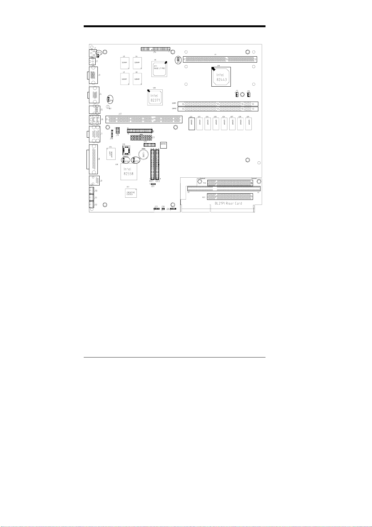
This chapter briefly describes each of the major features of the LI6BM
motherboard. The layout of the board in Figure 1 shows the location of
the key components. The topics covered in this chapter are as follows:
3.1 Processor ...................................................................................9
3.2 L2 Cache ...................................................................................9
3.3 BIOS..........................................................................................9
3.4 Main Memory..........................................................................10
3.5 I/O Port Address Map..............................................................11
3.6 DMA Channels........................................................................11
3.7 Onboard PCI-IDE....................................................................11
3.8 Interrupt Request (IRQ) Lines.................................................12
3.9 Onboard Multi-I/O ..................................................................12
3.10 Onboard VGA .......................................................................13
3.11 Onboard Audio......................................................................13
3.12 Onboard Ethernet Controller (option) ...................................14
3.13 Hardware Monitoring IC.......................................................14

Chapter 3 Hardware Description
8 LI6BM User’s Manual
Figure 1: Layout of the LI6BM Motherboard

Chapter 3 Hardware Description
LI6BM User’s Manual 9
3.1 Processor
The LI6BM motherboard is designed to take a Pentium II processor
running 233MHz/266MHz/300/333MHz at 66MHz CPU bus speed or
300/350/400/450/500MHz at 100MHz CPU bus speed with its Slot 1
processor connector.
3.2 L2 Cache
The L2 cache is integrated in the Pentium II processor. The private L2
cache bus is not connected to package pins; rather its signals are routed
between the two cavities using standard package techniques.
3.3 BIOS
The BIOS on the LI6BM motherboard provides the standard BIOS
functions plus the following additional features:
1. ISA Plug and Play (PnP) Extension
Unlike PCI cards that are Plug and Play, ISA cards require setting
jumpers to resolve hardware conflicts. To make a computer system
PnP, an ISA PnP standard is established and supported by new
operating systems, such as Windows 95. Under Windows 95, the
motherboard BIOS must have an ISA PnP extension to support new
ISA PnP cards.
2. Power Management
The power management feature provides power savings by slowing
down the CPU clock, turning off the monitor screen and stopping the
HDD spindle motor. The BIOS fully conforms to ACPI (Advanced
Configuration and Power Interface) specification.
Chapter 3 Hardware Description
10 LI6BM User’s Manual
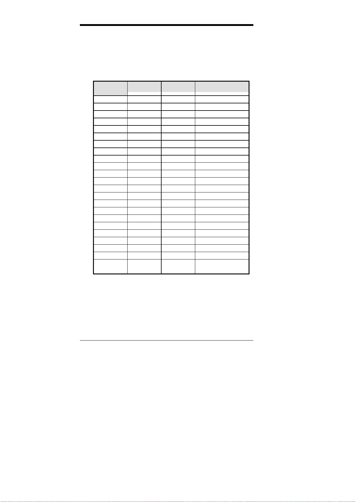
3.4 Main Memory
The LI6BM motherboard supports 64MB of DRAM memory on board
and two 168-pin DIMM (Dual In-line Memory Module) sockets to form
an additional memory of 256MB. Refer to the following table on how to
configure the memory.
168-pin DIMM (3.3V) SDRAM
Onboard
DRAM DIMM1 DIMM2 Total Memory
64MB ----- ----- 64MB
64MB 8MB ----- 72MB
64MB 8MB 8MB 80MB
64MB 8MB 16MB 88MB
64MB 8MB 32MB 104MB
64MB 8MB 64MB 136MB
64MB 8MB 128MB 200MB
64MB 16MB ----- 80MB
64MB 16MB 16MB 96MB
64MB 16MB 32MB 112MB
64MB 16MB 64MB 144MB
64MB 16MB 128MB 208MB
64MB 32MB ----- 96MB
64MB 32MB 32MB 128MB
64MB 32MB 64MB 160MB
64MB 32MB 128MB 224MB
64MB 64MB ----- 128MB
64MB 64MB 64MB 192MB
64MB 64MB 128MB 256MB
64MB 128MB ----- 192MB
64MB 128MB 128MB 320MB
64MB 256MB ----- 320MB
64MB 256MB 256MB 576MB
For 440BX only
NOTE: Use SDRAM modules with PC100 specification when running
100MHz CPU bus speed. With 66MHz CPU bus speed, SDRAM
modules with PC66 or PC100 specification can be used.

Chapter 3 Hardware Description
LI6BM User’s Manual 11
3.5 I/O Port Address Map
Each peripheral device in the system is assigned a set of I/O port
addresses, which also becomes the identity of the device. There is a total
of 1K port address space available. The following table lists the I/O port
addresses used on the motherboard.
Address Device Description
000h - 01Fh DMA Controller #1
020h - 03Fh Interrupt Controller #1
040h - 05Fh Timer
060h - 06Fh Keyboard Controller
070h - 07Fh Real Time Clock,, NMI
080h - 09Fh DMA Page Register
0A0h - 0BFh Interrupt Controller #2
0C0h - 0DFh DMA Controller #2
0F0h Clear Math Coprocessor Busy Signal
0F1h Reset Math Coprocessor
1F0h - 1F7h IDE Interface
2F8h - 2FFh Serial Port #2(COM2)
378h - 3FFh Parallel Port #1(LPT1)
3F0h - 3F7h Floppy Disk Controller
3F8h - 3FFh Serial Port #1(COM1)
3.6 DMA Channels
There are seven DMA channels available on the motherboard. Only
DMA2 is used by the floppycontroller. In the case that ECP mode on the
parallel port is utilized, DMA1 or DMA3 will be used.
3.7 Onboard PCI-IDE
The PCI-IDE controller isa part of the Intel 82440BX or VIA Apollo Pro
Plus(82C693) chipset. It supports PIO mode 3/4 and bus mastering Ultra
DMA/33. The peak transfer rate of PIO mode 3/4 can be as high as
17MB/sec. Using HDDs that support Ultra DMA/33, the peak transfer
rate can reach 33MB/sec. There are two IDE connectors - primary IDE
and secondary IDE. With two devices per connector, up to four IDE
devices can be supported.
Chapter 3 Hardware Description
12 LI6BM User’s Manual
3.8 Interrupt Request (IRQ) Lines
There are a total of 15 IRQ linesavailable on the motherboard. Peripheral
devices use an interrupt request to notify the CPU for the service
required. The following table shows the IRQ lines used bythe devices on
the motherboard:
Level Function
IRQ0 System Timer Output
IRQ1 Keyboard
IRQ2 Interrupt Cascade
IRQ8 Real Time Clock
IRQ9 Software Redirected to Int 0Ah or PCI Slot Int#
IRQ10 Reserved or PCI Slot Int#
IRQ11 Reserved or PCI Slot Int#
IRQ12 PS/2 Mouse or PCI Slot Int#
IRQ13 Co-Processor
IRQ14 Primary IDE
IRQ15 Secondary IDE
IRQ3 Serial Port #2
IRQ4 Serial Port #1
IRQ5 Parallel Port #2 or PCI Slot Int#
IRQ6 Floppy Disk Controller
IRQ7 Parallel Port #1
3.9 Onboard Multi-I/O
The onboard multi-I/O chip, W83977TF, supports a keyboard controller
(AMIcopyright), two serial ports, one parallel port, one floppy controller
and one IrDA port. The serial ports are 16550 UART compatible. The
parallel port features high-speed EPP/ECP mode. The floppy controller
supports up to 2.88 MB format.
The multi-I/O also features keyboard power-on that is configured in the
Power On Function field of the Integrated Peripherals section in the
BIOS. It allows users to enter a password of a maximum of five
characters (0~9, A~Z). Hot keys to power on supported are the function
keys (Ctrl-F1~Ctrl-F12).

Chapter 3 Hardware Description
LI6BM User’s Manual 13
3.10 Onboard VGA
The onboard 3D RAGE LT PRO is a highly integrated Multimedia/3D
Graphics Controller that has the following unique features:
• TV-Out
An integrated TV encoder with on-chip triple-DAC allows
simultaneous CRT/LCD/TV output.
• Dual CRT Controller Support
Two independent CRT controllers support two asynchronous
simultaneous displays (LCD/CRT, CRT/TV).
• Floating-Point Set-up Engine
The3D RAGE LT PRO integrates a floating-point se-up engine
capable of processing up to 1.2 million triangles per second.
By off-loading the set-up function from the CPU, allowing it to
focus on 3D geometry and lighting transformations, the 3D
RAGE LT PRO dramatically improves the performance of the
entire 3D pipeline.
• DVD and Video Support
DVD and video features include enhanced motion
compensation acceleration and a 4-tap horizontal and 2-tap
vertical high quality DVD video scaler, providing smooth
images without the “jaggies” (jagged edges) common to
today’s video products. The scaler provides true color video
display, independent of the graphics mode used.
• AGP 2X mode
The DVD enabled 3D RAGE LT PRO AGP 2X support the
AGP 2X (133MHz) mode that offers a peak bandwidth in
excess of 500MB/s. It supports AGP’s pipeline and sideband
protocols critical to the enhanced 3D and video performance.
• Panel Link Support (option)
The optional panel link connector supports new compact LCD
(Liquid Crystal Display) monitors that not only emit less
radiation and consume less power but take less space.
3.11 Onboard Audio
The onboard ES1373 is a Creative Labs AC97 digital controller, which
providesthe next generation ofaudio performance to the Sound Blaster
AudioPCIproduct line. It includes a complete audio recording and
playback system. The ES1373 interfaces to the PCI bus and to AC97, an
industry standard codec/mixer. This solution is Sound Blaster PCI
compatible utilizing a patented method of Sound Blaster emulation. In
addition, it is compliant to AC97 interface, Microsoft PC97 and PC98,
and Multimedia PC Level II and III specifications.

Chapter 3 Hardware Description
14 LI6BM User’s Manual
3.12 Onboard Ethernet Controller (option)
The onboard Intel 82558B Ethernet controller features the following:
•
••
•
PCI local bus
•
••
•
IEEE802.3u auto-negotiation for automatic speed selection
•
••
•
10/100Mbps operation in a single port PCI bus master
architecture
•
••
•
Wake On LAN function support
3.13 Hardware Monitoring IC
The LI6BM comes with the Winbond W83781D hardware monitoring
IC. It monitors several hardware parameters including power supply
voltages, fan speeds, and temperatures, which are very important for a
high-end computer system to work stable and properly.
Chapter 4 Configuring the Motherboard
LI6BM User’s Manual 15
Chapter 4 Configuring the Motherboard
The following sections describe the necessary procedures and proper
jumper settings to configure the LI6BM motherboard. For the locations
of the jumpers, refer to Figure 2.
4.1 CPU Frequency Selection........................................................17
4.2 Keyboard Power On Function: JP8, J10..................................17
4.3 Clear CMOS Select: JP11 .......................................................18
4.4 TV-Out Hardware Compliance Setting: JP12..........................18
4.5 CPU Host Frequency Force Selector: JP3...............................18
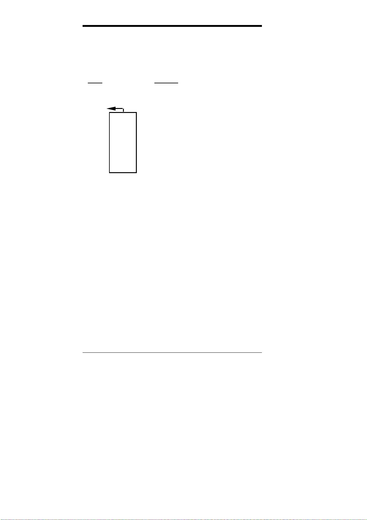
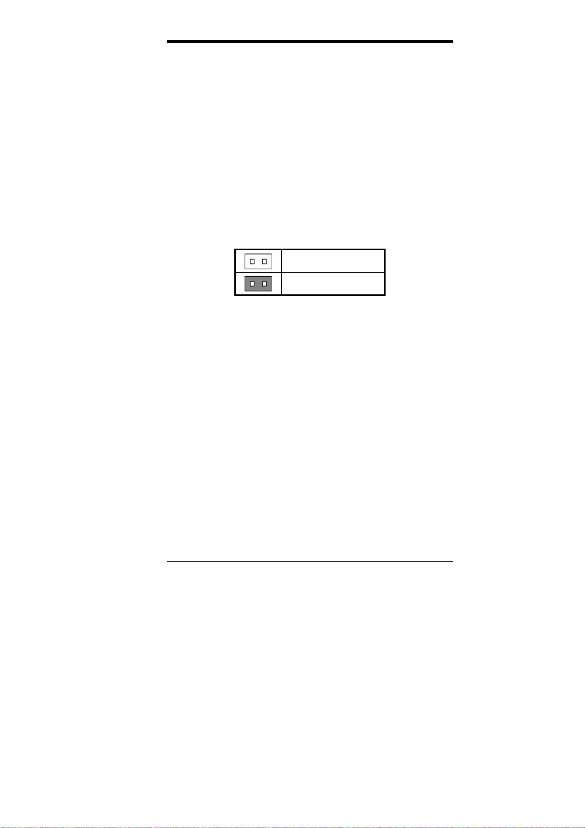
The following examples show the conventions used in this chapter.
Jumper Open
Jumper Closed/Short
Chapter 4 Configuring the Motherboard
16 LI6BM User’s Manual
Figure 2: Jumper Location on the LI6BM
Table of contents
Other TMC Motherboard manuals


Popular Motherboard manuals by other brands


Microchip Technology
Microchip Technology MCP401XEV user guide

IEI Technology
IEI Technology NANO-8522 user manual

Texas Instruments
Texas Instruments C28 Series user guide

NXP Semiconductors
NXP Semiconductors P1010RDB-PB quick start guide

Avnet
Avnet RZBOARD V2L Hardware user's guide

NXP Semiconductors
NXP Semiconductors i.MX 8MIC-RPI-MX8 quick start guide