TMG TMG-TFM60 User manual

v.2022.11.29
TRACTOR FLAIL MOWER
TMG-TFM60/68/72
tttttTFM60/TFM6
8/TFM72TFM60/TF
M68/TFM72

www.tmgindustrial.com 2 / 18 TOLL FREE: 1-877-761-2819
CONTENTS
IMPORTANT SAFETY INFORMATION .......................................................................................................................................................................2
Safety always........................................................................................................................................................................3
Transport machinery safely ................................................................................................................................................3
Safety Labels ........................................................................................................................................................................4
INTRODUCTION ......................................................................................................................................................................................................5
Using This Manual................................................................................................................................................................5
Terminology..........................................................................................................................................................................5
Owner Assistance.................................................................................................................................................................5
SECTION 1: ASSEMBLY AND SET-UP.......................................................................................................................................................................5
Tractor Requirements..........................................................................................................................................................6
Packing Description.............................................................................................................................................................6
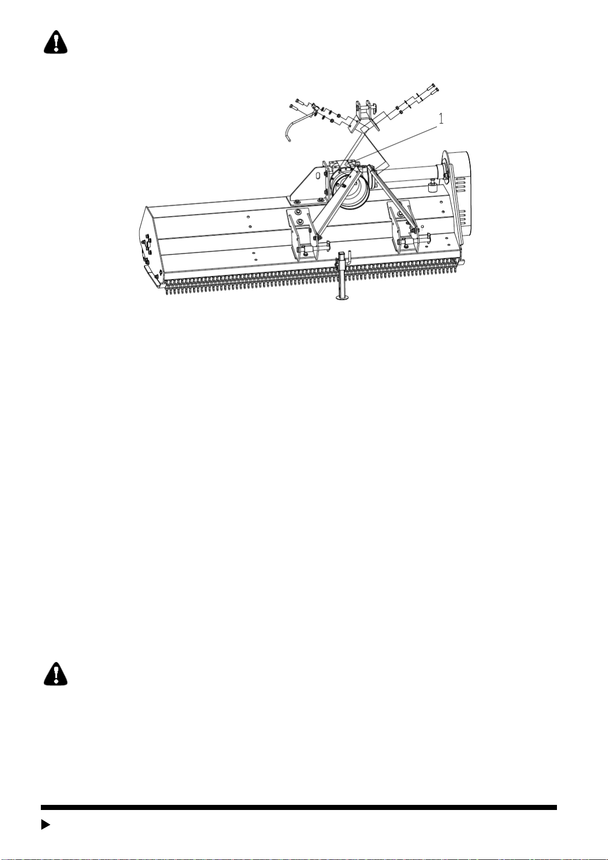
Installation Wizard ...............................................................................................................................................................7
Tractor Hook-Up...................................................................................................................................................................9
Driveline Installation ............................................................................................................................................................9
SECTION 2: OPERATING INSTRUCTIONS ................................................................................................................................................................. 9
Transporting .......................................................................................................................................................................10
Mowing Instructions ..........................................................................................................................................................10
Operating Instructions .......................................................................................................................................................10
SECTION 3: ADJUSTMENTS...................................................................................................................................................................................10
Leveling the Mower............................................................................................................................................................10
Cutting Height Adjustment................................................................................................................................................10
3-Point Hitch Adjustments................................................................................................................................................11
Belt Tension........................................................................................................................................................................11
SECTION 4: MAINTENANCE AND LUBRICATION...................................................................................................................................................... 11
Maintenance .......................................................................................................................................................................11
Knife Replacement.............................................................................................................................................................11
V-Belt Installation ..............................................................................................................................................................11
Storage................................................................................................................................................................................12
Lubrication..........................................................................................................................................................................12
SECTION 5: SPECIFICATIONS & CAPACITIES .........................................................................................................................................................12
SECTION 6: TROUBLESHOOTING............................................................................................................................................................................13
SECTION 7: APPENDIX...........................................................................................................................................................................................13
Warranty..............................................................................................................................................................................13
Bolt Torque .........................................................................................................................................................................14
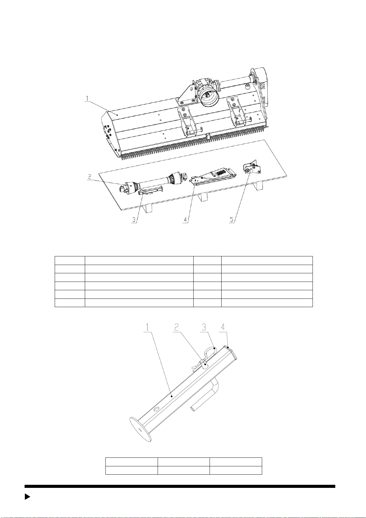
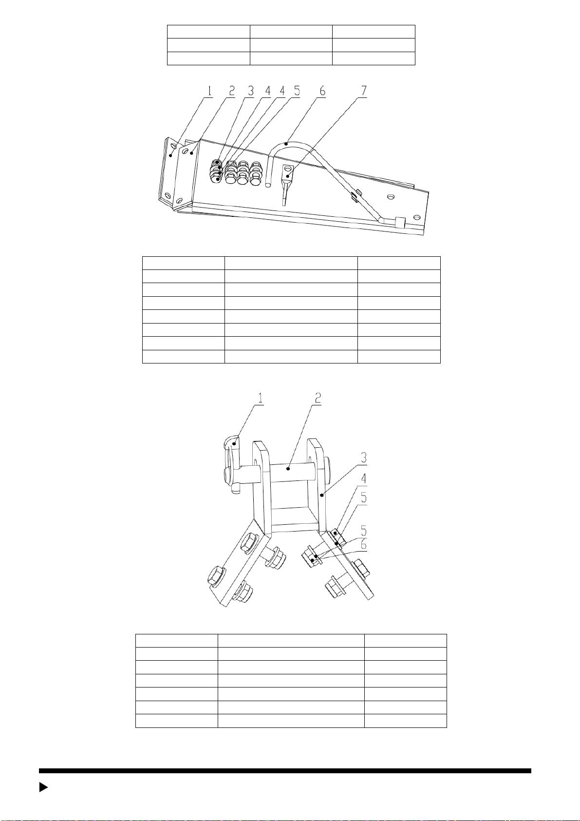
PART BREAKDOWN LIST .......................................................................................................................................................................................15
IMPORTANT SAFETY INFORMATION

www.tmgindustrial.com 3 / 18 TOLL FREE: 1-877-761-2819
Safety always
Thoroughly read and understand the instructions given in this manual before operation. Refer to the “Safety Decal”, read all
instructions noted on them.
Do not allow anyone to operate this equipment who has not fully read and comprehended this manual and who has not been
properly trained in the safe operation of the equipment.
1. Operator should be familiar with all functions of the unit. Operate implement from the driver’s seat only.
2. Make sure all guards and shields are in place and secured before operating the implement.
3. Do not leave tractor or implement unattended with engine running.
4. Dismounting from a moving tractor could cause serious injury or death.
5. Do not stand between tractor and implement during hitching.
6. Keep hands, feet, and clothing away from power-driven parts.
7. Wear snug fitting clothing to avoid entanglement with moving parts.
8. Watch out for wires, trees, etc., when raising implement. Make sure all persons are clear of working area.
9. Turning tractor too tight may cause implement to ride up on wheels. This could result in injury or equipment damage.
Look For the Safety Alert Symbol
The SAFETY ALERT SYMBOL indicates there is a potential hazard to personal safety involved and extra safety precaution
must be taken. When you see this symbol, be alert and carefully readthe message that follows it. In addition to design and
configuration of equipment,hazard controland accident prevention are dependent upon the awareness, concern,
prudence, and proper training of personnel involved in the operation, transport, maintenance and storage of equipment.
Be aware of signal words
A signal word designates a degree or level of hazard seriousness. The signal words are:
DANGER
Indicates an imminently hazardous situation which, if not avoids, will result in death or serious injury. This signal word is limited to
the most extreme situations, typically for machine components that, for functional purpose, cannot be guarded.
WARNING
Indicates a potentially hazardous situation which, if not avoided, could result in death or serious injury, and includes hazards that
are exposed when guards are removed. It may also be used to alert against unsafe practices.
CAUTION
Indicates a potentially hazardous situation which, if not avoided, may result in minor or moderate injury. It may also be used to
alert against unsafe practices.
For you protection
Thoroughly read and understand the “safety label” section, read all instructions noted on them.
Shut down and storage
Lower machine to ground, put tractor in park, turn off engine, and remove the ignition key.
Detach and store implements in a area where children normally do not play. Secure implement by using blocks and supports.
Use safety lights and devices
Slow moving tractors, self-propelled equipment, and towed implements can create a hazard when driven on public roads. They
are difficult to see, especially at night.
Flashing warning lights and turn signals are recommended whenever driving on public roads. Use lights and devices provided
with implement.
Transport machinery safely
1. Comply with state and local laws.

www.tmgindustrial.com 4 / 18 TOLL FREE: 1-877-761-2819
2. Maximum transport speed for implement is 20 mph. Do not exceed. Never travel at a speed which does not allow adequate
control of steering and stopping. Some rough terrain require a slower speed.
3. Sudden braking can cause a towed load to swerve and upset. Reduce speed if towed load is not equipped with brakes.
4. Use the following maximum speed - tow load weight ratios as a guideline:
5. 20 mph when weight is less than or equal to the weight of tractor.
6. 10 mph when weight is double the weight of tractor.
7. IMPORTANT: Do not tow a load that is more than double the weight of tractor.
Keep riders off machinery.
Riders obstruct of operator’s view, they could be struck by foreign objects or thrown from the machine.
Never allow children to operate equipment.
Practice safe maintenance
1. Understand procedure before doing work. Use proper tools and equipment. refer to Operator’s
2. Manual for additional information.
3. Work in a clean dry area.
4. Lower the implement to the ground, put tractor in park, turn off engine, and remove key before performing maintenance.
5. Allow implement to cool completely.
6. Do not grease or oil implement while it is operation.
7. Inspect all parts. Make sure parts are in good condition and installed properly.
8. Remove buildup of grease, oil or debris.
9. Remove all tools and unused parts from implement before operation.
10. Prepare for emergencies
11. Be prepared if a fire starts.
12. Keep a fist aid kit and fire extinguisher handy.
13. Keep emergency numbers for doctor, ambulance, hospital and fire department near phone.
Wear protective equipment.
1. Protective clothing and equipment should be worn.
2. Wear clothing and equipment appropriate for the job. Avoid loose fitting clothing.
3. Prolonged exposure to loud noise can cause hearing impairment or hearing loss. Wear suitable hearing protection such as
earmuffs or earplugs.
4. Operating equipment safely requires the full attention of the operator. Avoid wearing radio headphones while operating
machinery.
Avoid high pressure fluids hazard.
1. Escaping fluid under pressure can penetrate the skin causing serious injury.
2. Avoid the hazard by relieving pressure before disconnecting hydraulic lines.
3. Use a piece of paper or cardboard, not body parts, to check for suspected leaks. Wear protective gloves and safety
glasses or goggles when working with hydraulic systems.
4. If an accident occurs, see a doctor immediately. Any fluid injected into the skin must be treated within a few hours or
gangrene may result.
Safety Labels
Your Flail Mower comes equipped with all safety labels in place. They were designed to help you safely operate your implement.
Read and follow their directions.
1. Keep all safety labels clean and legible.
2. Replace all damaged or missing labels. To order new labels go to your nearest TMG dealer or visit our dealer locator at
TMG.com.
3. Some new equipment installed during repair requires safety labels to be affixed to the replaced component as specified
by TMG. When ordering new components make sure the correct safety labels are included in the request.

www.tmgindustrial.com 5 / 18 TOLL FREE: 1-877-761-2819
4. Refer to this section for proper label placement. To install new labels:
a. Clean the area the label is to be placed.
b. Spray soapy water on the surface where the label is to be placed.
c. Peel backing from label. Press firmly onto the surface.
d. Squeeze out air bubbles with the edge of a credit card.
Safety labels
This shows the grease position.
Introduction
TMG welcomes you to the growing family of new product owners. This implement has been designed with care and built by
skilled workers using quality materials. Proper assembly, maintenance, and safe operating practices will help you get years of
satisfactory use from the machine.
The Flail Mowers are designed for Category 1 - three point hitch or Quick-Hitch System mounting. These Fixed Bar Flail Mowers
are ideal for ripping, leveling, finish grading, and backfilling applications at feedlots, outdoor arenas, building sites, and
maintenance operations on farm and ranch lanes or roadways.
Using This Manual
1. This Operator’s Manual is designed to help familiarize you with safety, assembly, operation, adjustments, troubleshooting,
and maintenance. Read this manual and follow the recommendations to help ensure safe and efficient operation.
2. The information contained within this manual was current at the time of printing. Some parts may change slightly to
assure you of the best performance.
3. To order a new Operator’s or Parts Manual contact your authorized dealer. Manuals can also be printed from the TMG
Service & Support Center by your dealer.
Terminology
“Right” or “Left” as used in this manual is determined by facing the direction the machine will operate while in use unless
otherwise stated.
Note: A special point of information that the operator must be aware of before continuing.
Important: A special point of information related to its preceding topic. The intention is that this information should be read and
noted before continuing.
Owner Assistance
The Warranty Registration card should be filled out by the dealer at the time of purchase. This information is necessary to
provide you with quality customer service. If customer service or repair parts are required contact a dealer. A dealer has trained
personnel, repair parts and equipment needed to service the machine.
The parts on your machine have been specially designed and should only be replaced with genuine parts.
Serial Number Plate
For prompt service always use the serial number and model number when ordering parts from your dealer. Be sure to include
your serial and model numbers in correspondence also.
Section 1: Assembly and Set-up

www.tmgindustrial.com 6 / 18 TOLL FREE: 1-877-761-2819
Tractor Requirements
This mower is designed with a 3-Point category 1 hitch. Tractor horsepower rating should not exceed 50 PTO horse power.
Packing Description
1. Remove and check
Remove the packing, check goods without defect and omission.
Figure 1-1: The Mower and Accessory in Package
2. Packing List
The detailed packing list of the mower and accessory as the following table.
Item
Description
Qty.
Package Form
1
Main body of the mower
1
None
2
Driveline shaft
1
None
3
Raker sub-assembly
1
Bubble film
4
R&L hitch plates and fittings
1
Bubble film
5
Hitch bracket weldment and fittings
1
Bubble film
The detailed description of raker sub-assembly
Figure 1-2: Raker Sub-Assembly
Item
Description
Qty.
1
Raker weldment
1

www.tmgindustrial.com 7 / 18 TOLL FREE: 1-877-761-2819
2
Raker pin
1
3
R pin
1
4
Plastic plug
1
The detailed description of R&L hitch plates and fittings
Figure 1-3: R&L Hitch Plates and Fittings
Item
Description
Qty.
1
Hitch plate -R
1
2
Hitch plate -L
1
3
Locknut M12
4
4
Plain washer 12
8
5
Bolt M12x40
4
6
Driveline shaft hook
1
7
Hook bracket
1
The detailed description of hitch bracket weldment and fittings
Figure 1-4: Hitch Bracket Weldment–Upper and Fittings
Item
Description
Qty.
1
Safety lock pin
1
2
Hitch pin -Upper
1
3
Hitch bracket weldment-Upper
1
4
Bolt M12x40
4
5
Plain washer 12
8
6
Locknut M12
4
Installation Wizard
The installation wizard will guide you to finish the final assembly of your new mower easily.

www.tmgindustrial.com 8 / 18 TOLL FREE: 1-877-761-2819
1. Tool Required
1/2” Ratchet Wrench with 19mm sleeve
17-19 Spanner
2. Installation
Step1: Installing Raker Sub-Assembly
Remove the packaging of raker sub-assembly, pull out the R pin from the raker sub-assembly as well as the raker pin.
Insert the raker weldment into the tube on the hood panel as well as the raker pin, and insert R pin into the hole on the raker pin.
Figure1-5: Installing Aker Sub-Assembly
Step2: Installing R&L Hitch Plates and Fittings
Remove the packaging of R&L hitch plates and fittings.
Use 4pcs of BoltsM12x40, 8pcs of plain washers12 and 4pcs of locknutsM12 to fix R&L hitch plates to hitch bracket weldments
Lower on the hood panel.
Tighten locknuts completely.
WARNING
Fix R&L hitch plates in position 1 or 2 at the same time, otherwise the hitch bracket weldment-upper will not to be installed.
Figure1-6: Installing R&L Hitch Plates
Step3: Installing Hitch Bracket Weldment–Upper and Fittings
Remove the packaging of hitch bracket weldment –Upper and fittings.
Use 4pcs of BoltsM12x40, 8pcs of plain washers12 and 4pcs of locknutsM12 to fix hitch bracket weldment-upper, driveline
shaft hook and hook bracket with R&L hitch plates.
Tighten locknuts completely, and clip the driveline shaft hook into the hook holder on the hitch plate-L.

www.tmgindustrial.com 9 / 18 TOLL FREE: 1-877-761-2819
WARNING
Fill the item 1 with proper amount of gear oil in figure 8 before operation.
Figure1-8: Installing Hitch Bracket Weldment-Upper and Fittings
Tractor Hook-Up
1. Be certain that tractor draw bar will not interfere. Move draw bar ahead or remove if required. Draw bar should also be
checked for clearance when unit is being raised for the first time.
2. Align lower link arms of tractor to hitch clevises on mower. Insert lower hitch pins into lower ball swivels and attach link
pins.
3. Attach tractor top link to upper floating hitch on mower with pin supplied. Secure with lock pin.
4. Adjust tractor top link in or out to place upper hitch pin vertically above or slightly behind lower hitch pins to allow mower
flotation. The mower should be run with the back 15 degrees lower than the front.
Driveline Installation
1. Slide driveline end with extended safety cone over spline shaft of gearbox and secure with attaching device.
2. Slide driveline over tractor’s spline PTO shaft and secure with locking device of driveline.
3. Driveline should now be moved back and forth to ensure that it is secure on the PTO shaft of the tractor and mower
gearbox.
4. Attach chain from the driveline shield to one of the upper hitch braces to ensure that the shield does not rotate.
5. Should driveline require shortening:
a. Hold the half-shafts next to each other in the shortest working position andmark them.
b. Shorten inner and outer guard tubes equally.
c. Shorten inner and outer sliding profiles by the same length as the guard tubes.
d. Proper overlap is a minimum of one-half the length of each tube, with both tubes being of equallength.
e. Round off all sharp edges and remove burrs. Grease sliding profiles.
CAUTION
Tractor PTO shield and all mower guards must be always in place during operation!
Section 2: Operating Instructions

www.tmgindustrial.com 10 / 18 TOLL FREE: 1-877-761-2819
Transporting
NOTE: Always disengage PTO before raising mower to transport position.
1. When raising the mower to transport position, be sure that driveline does not contact tractor or mower. Adjust and set the
tractor’s 3-point hitch lift height so that the driveline does not contact mower deck in the fully raised position.
2. Be sure to reduce tractor ground speed when turning, leaving enough clearance so that the mower does not contact
obstacles such as buildings, trees or fences.
3. Select a safe ground travel speed when transporting from one area to another. When traveling on roadways, transport in
such a way that faster moving vehicles may pass safely.
4. When traveling over rough or hilly terrain, shift tractor to a lower gear.
CAUTION
When traveling on publicroads, whether at night or during the day, use accessory lights and devices foradequate warning to
operators of other vehicles. Comply with all Federal, State, and local laws.
Mowing Instructions
1. Clear area to be mowed of objects and debris that might be picked up and thrown by the mower blades.
2. Grass is best cut when it is dry. Mowing wet grass can cause plugging resulting in grass clumps behind the mower.
3. Grass should be mowed frequently as shorter clippings deteriorate faster.
4. If mowing extremely tall grass, it is best to raise cutting height and mow the area, then lower cutting height and mow a
second time at the desired height.
Operating Instructions
Proper servicing and adjustments are the key to the long life of any machine. With careful and systematic inspection of the mower,
costly maintenance, time and repair can be avoided.
Before beginning to mow, the following inspection should be performed:
1. Check oil level in gearbox.
2. Check that all plugs in gearbox have been replaced and tightened properly.
3. Be sure all mower knives, bolts and nuts are tight.
4. Be certain all guards and shields are in place and secure.
5. Grease driveline shaft and all other grease fittings.
6. Clear area to be mowed of rocks, branches and other foreign objects.
7. Lower mower to ground. Set tractor throttle at approximately 1/4 open. Engage PTO to start blades rotating.
8. Operate with 540 rpm PTO tractor.
9. At first begin mowing at a slow forward speed and shift up until the desired speed is achieved - maintaining 540 PTO rpm.
10. Mower knives will cut better at a faster blade speed than at reduced throttle.
11. After mowing the first 50 feet, stop and check to see that the mower is adjusted properly.
12. Do not make sharp turns or attempt to back up while mower is on the ground.
13. Do not engage PTO with mower in the fully raised position. Do not engage PTO at full throttle.
Section 3: Adjustments
Leveling the Mower
NOTE: Tractor and mower should be on level ground.
Leveling can be adjusted at the tractor’s 3-point arms and center link.
Cutting Height Adjustment
The machines cutting height depends upon the position of the rear roller.
1. Remove the bolts that fix the roller on both sides.

www.tmgindustrial.com 11 / 18 TOLL FREE: 1-877-761-2819
2. Lift or lower both sides of roller in equal measurements.
3. Replace bolts and re-tighten.
3-Point Hitch Adjustments
The 3-point hitch system on this mower has been designed for front to back flotation when mowing on uneven terrain. Adjust tractor’s
top center link to place the upper hitch pin vertically above or slightly behind the lower hitch pins. The mower should be run with the
back 15 degrees lower than the front.
The hitch can also be adjusted from side to side by turning the adjustment handle. Turn handle until you have achieved your desired
location.
CAUTION
Engage parking brake, shut off tractor, remove key and disengage PTO before making any heightadjustments!
Belt Tension
CAUTION
Belt drive system under spring tension; use care to avoid bodily harm!
The Belt tension should be checked after the first 20 hours of use. And then every 40 hours of use.
1. Tension on the belt can be adjusted with the belt tension bolt. Turn the bolt until desired tension is achieved. When the
belt has the correct tension the gearbox should be adjusted so that the gearbox extension is running straight (parallel)
with the flail mower. Loosen bolts at the bottom of the gearbox and move gearbox until gearbox extension is running
straight.
2. Excessive tension on the belt may lead to premature failure of belt and drive components.
CAUTION
Excessive tension on the belt may lead to premature failure of belt and drive components. Excessivetension on the belt
may also lead to a safety hazard to the operator or bystanders.
Section 4: Maintenance and Lubrication
Maintenance
Proper servicing and adjustment is the key to the long life of any farm implement. With careful and systematic inspection, you can
avoid costly maintenance, time and repair.
CAUTION
For safety reasons, each maintenance operation must be performed with tractor PTO disengaged,mower lowered completely to
ground and tractor engine shut off with ignition key removed.
1. After using the mower for several hours, check all bolts to be sure they are tight and check drive belt tension.
2. Replace any worn, damaged or illegible safety decals by obtaining new decals from dealer.
Knife Replacement
IMPORTANT:Make sure that the knife is the same length as the others on the mower. This will keep the rotor rotation balanced.
1. Remove bolt and nut.
2. Remove old knife.
3. Install new knife and existing bolt.
4. Secure with nut.
V-Belt Installation
CAUTION

www.tmgindustrial.com 12 / 18 TOLL FREE: 1-877-761-2819
Belt drive system under spring tension; use care to avoid bodily harm!
1. Remove belt guard fender and belt cover.
2. Disengage belt tension by loosening belt tension bolt until belt can be removed.
3. With tension relieved from belt remove old belt from pulleys.
4. Tighten belt tension bolt.
5. Reinstall belt guard and belt guard fender.
Storage
At the end of the working season or when the mower will not be used for a long period, it is good practice to clean off any dirt or
grease that may have accumulated on the mower and any of moving parts.
1. Clean as necessary.
2. Check knives for wear and replace if necessary.
3. Inspect mower for loose, damaged or worn parts and adjust or replace as needed.
4. Store unit inside if possible for longer life.
5. Repaint parts where paint is worn or scratched to prevent rust.
6. Replace all damaged or missing decals.
Lubrication
Driveline Shaft U-Joints
Type of Lubrication: Multi-purpose Grease
Roller Bearing (Both Ends)
Type of Lubrication: Multi-purpose Grease
Cutter Rotor Bearing (Both Ends)
Type of Lubrication: Multi-purpose Grease
Gearbox
Type of Lubrication: SAE 90W Gear Lube
Check oil level in gearbox by removing the plug located on the right-hand side. Oil should be level with bottom of plug hole. Add oil if
necessary, by removing top fill plug and side plug. Add oil until it flows from side plug hole.
Do not overfill!
IMPORTANT: Mower should be level when checking oil in gearbox!
Driveline Profiles
Type of Lubrication: Multi-purpose Grease
Section 5: Specifications & Capacities
TMG-TFM Series Mower Specifications
MODEL
TMG-TFM60
TMG-TFM68
TMG-TFM72
CUTTING WIDTH
1550mm
1750mm
1850mm
BLADE NUMBER
24 flail hammers
28 flail hammers
32 flail hammers
PTO TURNNING SPEED
540r/min
540r/min
540r/min
POWER REQUIRED
30-60hp
30-60hp
30-60hp
PRODUCT WEIGHT
270kg
290kg
310kg

www.tmgindustrial.com 13 / 18 TOLL FREE: 1-877-761-2819
Section 6: Troubleshooting
Problem
Solution
Do not try to clean rear discharge area when mower is running. Bodily harm may occur!
Belt slipping
Unplug and clean mower deck.
Remove belt guard shields and clean sheaves.
Replace belt.
Mow at full throttle (540 PTO rpm), check PTO speed and tractor engine.
Patches of uncut grass
Shift transmission to a lower gear.
Tighten belts.
Replace missing knives.
Replace knives.
Excessive vibration
Replace drive belt.
Replace pulleys or align.
Remove belt guard shields & clean debris from belt area & sheaves.
Gearbox noisy
Check lubricant level.
Knives scalping grass
Raise cutting height by adjusting roller.
Change mowing pattern.
Reduce speed turns.
Uneven cut
Shift to a lower gear.
Level mower.
Replace missing knives.
Tractor loaded down by
mower
Mow at full throttle (540 PTO rpm).
Shift to a lower gear.
Clean mower.
Section 7: Appendix
Warranty
TMG warrants to the original purchaser that this product will be free from defects in material and workmanship beginning on
the date of purchase by the end user according to the following schedule when used as intended and under normal service and
conditions for personal use.
Overall Unit and Driveline: One-year.
Blades and Belts: Considered wear items.
This warranty is limited to the replacement of any defective part by manufacturer and the installation by the dealer of any such
replacement part, and does not cover common wear items such as blades, belts, tines, etc. TMG reserves the right to inspect
any equipment or parts which are claimed to have been defective in material or workmanship.
This warranty does not apply to any part or product which in TMG’s judgment shall have been misused or damaged by accident
or lack of normal maintenance or care, or which has been repaired or altered in a way which adversely affects its performance
or reliability, or which has been used for a purpose for which the product not designed. Misuse also specifically includes failure
to properly maintain oil levels, grease points, and driveline shafts.
Claims under this warranty must be made to the dealer which originally sold the product and all warranty adjustments must be
made through such dealer. TMG reserves the right to make changes in materials or design of the product at any time without
notices.

www.tmgindustrial.com 14 / 18 TOLL FREE: 1-877-761-2819
This warranty shall not be interpreted to render TMG liable for damages of any kind, direct, consequential, or contingent to
property. Furthermore, TMG shall not be liable for damages resulting from any cause beyond its reasonable control. This
warranty does not extend to loss of crops, any expense or loss for labor, supplies, rental machinery or for any other reason.
No other warranty of any kind whatsoever, express or implied, is made with respect to this sale; and all implied warranties of
merchantability and fitness for a particular purpose which exceed the obligations set forth in this written warranty are hereby
disclaimed and excluded from this sale.
Bolt Torque
The tables shown below give correct torque values for various bolts and cap screws. Tighten all bolts to the torques specified
unless otherwise noted. Check tightness of bolts periodically, using bolt torque chart as a guide. Replace hardware with the
same strength bolt.
ENGLISH TORQUE SPECIFICATIONS
Bolt Diameter
Bolt Torque
SAE 2
N.m lb-ft
SAE 5
N.m lb-ft
SAE 8
N.m lb-ft
1/4”
8
6
12
9
17
12
5/16”
13
10
25
19
36
27
3/8”
27
20
45
33
63
45
7/16”
41
30
72
53
100
75
1/2”
61
45
110
80
155
115
9/16”
95
60
155
115
200
165
5/8”
128
95
215
160
305
220
3/4”
225
165
390
290
540
400
7/8”
230
170
570
420
880
650
METRIC TORQUE SPECIFICATIONS
Bolt Diameter
Bolt Torque
8.8
N.m lb-ft
10.9
N.m lb-ft
M3
0.5
0.4
1.8
1.3
M4
3
2.2
4.5
3.3
M5
6
4
9
7
M6
10
7
15
11
M8
25
18
35
26
M10
50
37
70
52
M12
90
66
125
92
M14
140
103
200
148
M16
225
166
310
229
M20
435
321
610
450
M24
750
553
1050
744
M30
1495
1103
2100
1550
M36
2600
1917
3675
2710
Torque figures indicated above are valid for non-greased or non-oiled threads and heads otherwise specified. Therefore, do not
grease or oil bolts or cap screws unless otherwise specified in this manual. When using locking elements, increase torque
values by 5%.

www.tmgindustrial.com 15 / 18 TOLL FREE: 1-877-761-2819
Part Breakdown List
TMG-TFM60/TMG-TFM68/TMG-TFM72 Part Breakdown

www.tmgindustrial.com 16 / 18 TOLL FREE: 1-877-761-2819
TMG-TFM60/ TFM68/ TFM72 Part Breakdown List
PART NO.
REF. NO.
PART DESCRIPTION
QTY.
REMARK
1
4030100004
Hood panel
1
TMG-TFM60
4030100006
1
TMG-TFM68
4030100007
1
TMG-TFM72
2
EFGC155.07.00.000
Gearbox drive assembly
1
TMG-TFM60
EFGC175.07.00.000
1
TMG-TFM68, TMG-TFM72
3
4030100009
Skate - L
1
4
4030100010
Skate - R
1
5
7040100006
Plain washer 12
56
6
7010100005
Bolt M12x35
12
7
7030500006
Locknut M12 class 8
12
8
7030400001
Nut M16x1.5
1
9
7010300003
Bolt M16x1.5x50
1
10
4030100011
Gearbox mounting bracket
1
11
7040300006
Large plain washer 12
13
12
7040400006
Spring washer 12
17
13
7030500018
Locknut M12 class 5
16
14
7010100008
Bolt M12x40
20
15
4030100012
Raker
1
16
4020000007
Raker pin
1
17
4300100001
R pin φ4x75
1
18
4010000014
Tension plate
1
19
7040300007
Large plain washer 14
2
20
7040100007
Plain washer 14
2
21
7030500007
Locknut M14
2
22
7010100009
Bolt M14x35
2
23
4050000003
Driving pulley - 3 grooves
1
TMG-TFM60
4050000001
Driving pulley - 4 grooves
1
TMG-TFM68, TMG-TFM72
24
4050000004
Driven pulley - 3 grooves
1
TMG-TFM60
4050000002
Driven pulley - 4 grooves
1
TMG-TFM68, TMG-TFM72
25
4130000001
Swellable sleeve Z3-35x60
2
26
4150100001
Belt B991
3
TMG-TFM60
4
TMG-TFM68, TMG-TFM72
27
4030100014
Pulley cover
1
TMG-TFM60
4030100013
1
TMG-TFM68, TMG-TFM72
28
7010200002
Bolt M12x130
1
TMG-TFM60
7010200001
Bolt M12x110
1
TMG-TFM68, TMG-TFM72
29
7070100002
Bearing seat
2
30
4030100018
Roller
1
TMG-TFM60
4030100020
1
TMG-TFM68
4030100021
1
TMG-TFM72
31
4010000015
Roller mounting plate - R
1
32
4010000016
Roller mounting plate - L
1

www.tmgindustrial.com 17 / 18 TOLL FREE: 1-877-761-2819
33
4030100025
Mud shield
4
TMG-TFM60
4030100027
6
TMG-TFM68
4030100028
7
TMG-TFM72
34
7040100004
Plain washer 8
6
35
7030500016
Locknut M8
2
36
4020000012
Guard chain rod
1
TMG-TFM60
4020000014
1
TMG-TFM68
4020000015
1
TMG-TFM72
37
7040100005
Plain washer 10
2
38
7100100001
Cotter pin φ3x25
2
39
4030100029
Hitch bracket - lower
2
40
4010000020
Splint
4
41
4020000018
Hitch pin - lower
2
42
4300100004
Safety lock pin φ11x50
3
43
4020000019
Hitch pin spacer
2
44
4030100032
Hitch bracket - upper
1
45
4030100030
Hitch bracket -L
1
46
4030100031
Hitch bracket -R
1
47
4020000017
Hitch pin - upper
1
48
4010000021
Hook holder
1
49
4010000022
PTO hook
1
50
4100200006
PTO dust cover
1
51
7040400004
Sping washer 8
4
52
7010100006
Bolt M8x20
4
53
4300400002
Pressure lubricator M8x1
2
54
7070100003
Bearing seat
2
55
7010100004
Bolt M12x30
8
56
4100500002
Oil seal TC55x80x8
1
55
4020000022
Oil seal sleeve L=48
1
TMG-TFM60
4020000020
Oil seal sleeve L=65
1
TMG-TFM68, TMG-TFM72
58
4030100036
Blade axle
1
TMG-TFM60
4030100038
1
TMG-TFM68
4030100039
1
TMG-TFM72
59
4100200007
Cover 30x30
1
60
7010500006
Bolt M16x1.5x85
24
TMG-TFM60
28
TMG-TFM68
32
TMG-TFM72
61
7030800001
Locknut M16x1.5
24
TMG-TFM60
28
TMG-TFM68
32
TMG-TFM72
62
4290200002
Hammer blade
24
TMG-TFM60
28
TMG-TFM68
32
TMG-TFM72
63
7020300001
HSCHS M8x25
10
64
7110200001
Spring holder φ10
1

www.tmgindustrial.com 18 / 18 TOLL FREE: 1-877-761-2819
65
7040400001
Spring washer 4
1
66
7020500001
PHSCS M4x10
1
67
4020000040
Chain spacer
68
TMG-TFM60
77
TMG-TFM68
81
TMG-TFM72
68
4270100002
Guard chain
67
TMG-TFM60
76
TMG-TFM68
81
TMG-TFM72
69
4100200010
Round plug φ14 orange
11
TMG-TFM60/TMG-TFM68/TMG-TFM72 Gearbox Assembly Breakdown
PART NO.
REF. NO.
PART DESCRIPTION
QTY.
REMARK
1A
4040100002
50HP Gearbox
1
2A
4020000005
Shaft sleeve
1
3A
4020000024
Shaft
1
TMG-TFM60
4020000006
1
TMG-TFM68, TMG-TFM72
4A
7080100001
Key A 10x40
1
5A
4030100008
Shaft tube
1
6A
7040400006
Spring washer 12
4
7A
7020100002
HSCS M12x35
4
8A
7060100001
Deep groove ball bearing 6207-
2RS
1
9A
4100500001
Oil seal TC35x72x10
1
10A
7090200001
Clicirp for hole φ72
1
This manual suits for next models
2
Table of contents
Other TMG Lawn Mower manuals