TMG TMG-TMO70 User manual

70” 3-POINT HITCH
ORCHARD FINISHING MOWER
PRODUCT MANUAL
v2023.03.02
TMG-TMO70
Please read and understand the product manual completely before assembly
Check against the parts list to make sure all parts are received
Wear proper safety goggles or other protective gears while in assembly
Do not return the product to dealer. They are not equipped to handle your requests.
Missing parts or questions on assembly?
Please call: 1-877-761-2819 or email: cs@tmgindustrial.com

IMPORTANT SAFETY INFORMATION..............................................................................................3
GENERAL SAFETY GUIDELINES......................................................................................................4
PRODUCTS SPECIFICATIONS.......................................................................................................7
PARTS DESCRIPTION AND FUNCTION.........................................................................................8
SAFETY DECAL LOCATIONS.........................................................................................................9
UNPACKING & ASSEMBLY............................................................................................................11
CONNECTING TRACTOR...............................................................................................................18
PRIOR TO OPERATION..................................................................................................................20
MAINTENANCE.............................................................................................................................24
STORAGE......................................................................................................................................28
TROUBLESHOOTING.....................................................................................................................28
EXPLODED VIEW & PARTS LIST...................................................................................................30
TABLE OF CONTENTS

Before operating the MOWER read the following safety instructions. Failure to comply with these
warnings may result in serious injury or death.
Safety Instructions
Good safety practices not only protect you but also the people around you. Please ensure that everyone using his equipment is
familiar with the recommended operating and maintenance procedures, has read and understood the Operators Manual and
follows all the safety precautions. Most accidents can be prevented. Do not risk serious injury or death by ignoring good safety
practices.
The alert symbol is used throughout this manual and this manual and on the product safety decals. This symbol indicates
attention is required and identifies hazards concerning your personal safety and the safety of others. Please follow the
recommended precautions
The safety alert symbol means...
ATTENTION! BECOME ALERT! YOUR SAFETY IS INVOLVED!
NOTICE -Indicates a situation that could result in damage to the machine or other property.
IMPORTANT SAFETY INFORMATION
CAUTION
Indicates a potentially hazardous situation that, if not avoided, may result in minor or moderate injury. It may also
be used to alert against unsafe practices.
WARNING
Indicates a potentially hazardous situation that, if not avoided, could result in death or serious injury, and includes
hazards that are exposed when guards are removed. It may also be used to alert against unsafe practices.
DANGER
Indicates an imminently hazardous situation that, if not avoided, will result in death or serious injury. This signal
word is to be limited to the most extreme situations typically for machine components which, for functional
purposes, cannot be guarded.

•Have a first-aid kit available for use and know how to use it.
•Have a fire extinguisher available, stored in a highly visible location and know how to use it.
•Wear appropriate protective gear. This list may include but is not limited to:
- hard hat
- protective shoes with slip resistant soles and steel caps
- protective glasses or goggles
- heavy gloves
- wet weather gear
- hearing protection
- respirator or filter mask
•Read and understand the Operator's Manual and all safety decals before operating, servicing, adjusting, repairing or hitching
the equipment.
•Do not attempt any unauthorised modifications to your product as this could affect function or safety and could affect the
life of the equipment.
•Never start or operate the Mower except from the operators station on the power unit.
•Inspect and clean the working area before operating. Remove all obstructions such as rocks, stumps and wire.
•Keep hands, feet, clothing, and hair away from moving parts.
•Ensure bystanders are clear of the area before operating. A minimum distance of 100 meters should be kept from all
bystanders when Mower is in operation.
•Never operate this equipment while using alcoholic beverages or drugs that can hinder alertness or coordination. Consult
your doctor about operating this machine while taking any medication.
•Under no circumstances should children under the age of 18 be allowed to work with or around this equipment. Do not allow
anyone to operate or assemble this equipment until they have read and understood this manual.
•This equipment is dangerous to anyone unfamiliar with its operation. The operator should be responsible, properly qualified
and physically able person familiar with farm machinery and competent in this equipment operation.
•All new operators or owners must review the manual before using the equipment and at least annually thereafter.
•In order to provide a clear view, certain illustrations in this manual may show an assembly with a safety guard removed
equipment should never be operated in this condition. Keep all guards in place. If guard removal becomes necessary for
repairs, reinstall the guards prior to use.
•Replace any safety decal that is not legible or is missing. The locations of such safety decals are indicated in this manual.
•Never exceed the limits of a piece of machinery. If its ability to do a job, or to do so safely, is in question -DONT TRYIT.
•In addition to the design of this implement, safety decals and safety equipment, accident prevention is dependent upon the
awareness, common sense, forethought, and proper training of everyone involved in the operation, transport, maintenance
and storage of the machine. Also refer to safety messages and operating instructions in each of the appropriate sections of
the tractor manual. Pay close attention to the safety decals affixed to the tractor and the Mower.
GENERAL SAFETY GUIDELINES

Employer/Controller Responsibilities
OH&S legislation places obligations on the employer, or the controller of the Mower, to identify the hazards and control the
risks associated with the use of the Mower in their workplace and to do so in accordance with the manufacturer's instructions.
When purchasing a Mower:
1. Ensure the manufacturer's instructions are provided at the point of purchase.
2. Ensure the Mower conforms to industry safety standards.
3. Discuss your needs with the supplier, to ensure the Mower is compatible with the power of your tractor and is appropriate
for The intended application-consider the speed of your tractor's PTO and its compatibility with the Mower's gearbox.
4. Seek practical advice and instruction from the supplier on the use and limitations of the Mower. If you are hiring, leasing or
borrowing a Mower on a temporary basis, get safe use instructions from the person supplying it.
5. The employer must provide safety instructions to all those involved in using a Mower.
6. A copy of safety instructions must be kept in good condition with the Mower.
Generally, the safety instructions should be the manufacturer's instructions. Any variations from the manufacturer's
instructions must be based on a risk assessment and must not remove any of the safety features nor expose anyone to risks.
Supervision, Instruction and Training
The employer must provide safe systems of work, adequate supervision, instruction and training to all those involved in using a
Mower. They must be instructed in the safe operation of the Mower, including hazards specific to the workplace, including the
terrain, stability of the tractor, working environment and the like. The employer should ensure that everyone achieves a level of
understanding that enables them to safely and competently operate the Mower.
Inspection,Maintenance and Repair
The Mower must be inspected according to the manufacturer's instructions, prior to use. See page 23 for Maintenance
Instructions.
All problems identified must be rectified,prior to use.
The Mower must be maintained according to the manufacturer's instructions.
Replacement parts must be to the original manufacturer's specifications or their equivalent.
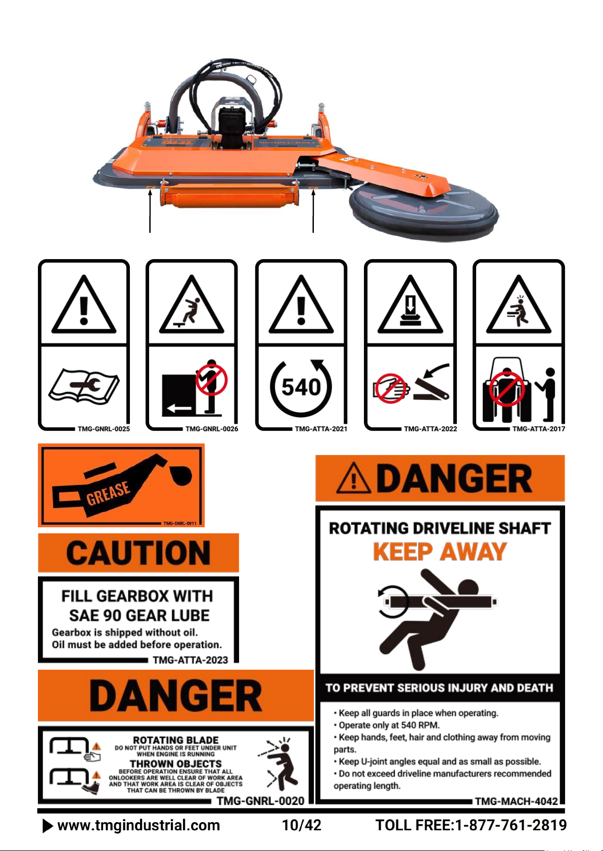
Safety signs and decals should be legible,maintained and where necessary replaced. ·Repairs should be carried out by a
competent person.
When suspending the Mower for maintenance or repair, whether attached to the tractor or suspended in another way, adequate
safety stands must be used to prevent inadvertent lowering of the Mower.
Service and Maintenance Safety
Stop engine, set brake, remove ignition key and wait for all moving parts to stop before servicing, adjusting, repairing or
unplugging.
Support the equipment with blocks or safety stands before working beneath it.
Follow good shop practices including:
-keep service area clean and dry
-be sure electrical outlets and tools are properly grounded
-use adequate light for the job.
Use only tools, jacks and hoists of sufficient capacity for the job.
Replace and secure all shields removed during servicing before operating.
Use heavy leather gloves to handle sharp objects.

Start-up Safety
Do not let inexperienced operators or children use this equipment.
Place all tractor and machine controls in neutral before starting.
Operate only with Roll Over Protective System(ROPS) and seat belt equipped tractors.
Do not operate inside a building unless there is adequate ventilation.
Ensure all shields are in place and in good condition before operating.
Stay clear of PTO shaft and machine when engaging PTO.
Operation
Prior to use, the Mower should be inspected to ensure it is working correctly. All safety features must be included in this
inspection. If any safety feature is not working correctly, the Mower must not be used. The Mower must be operated according
to the manufacturer's instructions.
The operator must ensure that no-one is exposed to risks arising from the slashing operation.
Additional safety controls may be required when operating in the vicinity of people or traffic - e.g. alongside highways, roads or
other public areas.
Where adjustable or removable guarding is provided for specific applications, such as vineyards and horticulture, and the
guarding has been removed or is no longer effective, appropriate control measures must be implemented. These controls must
ensure that the risk of injury is eliminated or controlled. Before using a Mower in an application other than that outlineed above,
the guards must be readjusted or replaced so as to be effective.
Operation Safety
Do not permit riders.
Do not wear loose fitting clothing during operation.
Never operate over 540 PTO rpm speed.
Never operate the equipment in the raised position.
Personal Protective Equipment(PPE)
Prior to use, a risk assessment must be undertaken to determine the appropriate PPE required. Any identified PPE must be
provided by the employer and must be used by those involved in the operation and maintenance of the Mower. Examples of
PPE are appropriate footwear and hearing & eye protection.
Storage and Transport
When not in use, the Mower must be transported and stored according to the manufacturer's instructions. Requirements may
differ when transporting a Mower within a property and on a public road - you must comply with all statutory requirements.
Storage Safety
Store the unit in an area away from human activity.
Do not permit children to play on or around the stored machine.
Support the frame on stands and blocks to provide a secure base.

Transport Safety
Review Transport Safety instructions in tractor manual before moving.
Check with local authorities regarding transport on public roads. Obey all applicable laws and regulations.
Make sure the SMV (Slow Moving Vehicle) emblem and all the lights and reflectors that are required by the local highway and
transport authorities are in place, are clean, and can be seen clearly by all overtaking and oncoming traffic.
Never have the equipment in operation during transport.
Always travel at a safe speed.
Modifications
A Mower should not be modified or altered. However, if it is necessary to make modifications, they must be done by a
competent person and based on a risk assessment. All modifications must comply with this industry safety standard.
Before any modifications are done, contact the manufacturer or supplier.
Anyone who undertakes modifications subsequently assumes the role and responsibilities of the designer and manufacturer.
This does not include shortening a PTO shaft and cover when first installing the Mower on a tractor (refer to page 19 for
details). The instructions relating to the Mower and its use may need to be revised following a modification. Any modifications
made without manufacturers approval will void Warranty.
Safety Signs
Refer pages 9-10 for the approximate location and detail of safety signs.
Keep all safety signs clean and legible and replace any that are damaged or missing.
When original parts are replaced, any safety signs affixed to those parts should be replaced as well. Replacement safety signs
are available from your local dealer.
Installation of Safety Signs
To install safety signs, ensure the installation area is clean and dry. Decide on the exact position before you remove the
backing paper. Remove the smallest portion of the split backing paper and align over the specified area. Carefully press in
place.
Slowly peel back the remaining paper and smooth the remaining portion in place. Small air pockets can be pierced with a pin
and smoothed out.
Model
TMG-TMO70
Working width
70”
Max. working width
85”
Cutting height
1”-3”
Blade No
8
Tractor horsepower
30~50 HP
PTO speed
540 RPM
Power From
PTO shaft
Hitch type
CAT 1
3-point suspension offset
12”
Weight
800lb
Packing Size
76”x45”x24”
PRODUCTS SPECIFICATIONS

1. PTO shaft ——
Transfer
the tractor power output to the gearbox.
2. Three point suspension assembly——linkage Connect tractor and Mower.
3. Hydraulic lateral moving components——
Push the mower left and right with the hydraulic cylinde
r t
o control
the mowing range.
4. Gearbox ——
Change the output speed of the tractor and transmit power to the blade axle.
5. Roller assembly ——
provide support for the mower during operation, to block and flatten the cut grass and adjust
the mowing height.
6. Wheel fork assembly ——
when mowing normally, adjust cutting height.
7.Floating cutter assembly ——
used to remove weeds near obstacles.
8. Inspection cover——
a part convenient for maintenance and inspection of mowing components.
PARTS DESCRIPTION AND FUNCTION

The safety decals and their positions are shown on the illustration below. Good safety requires that you familiarize yourself with
the various safety decals, the type of warning and the area or specific function related to that area that requires your SAFETY
AWARENESS.
2017
0026
4042
2023
0020
0011
SAFETY DECAL LOCATIONS
2022
0011
0025
2022
2021
0011
0011

0011
0011

NG
&
A
SS
E
M
B
L
Y
1. After unpacking, check the following components
The parts marked with numbers in the figure are the parts that need to be assembled.
*. All numbers are not part numbers in the drawings. For correct part numbers, see explosive diagram.
UNPACKING & ASSEMBLY

NO.
DESCRIPTION
QTY
NO.
DESCRIPTION
QTY
1
Host
1
13
Full thread hexagon bolt M10x20
11
2
Roller assembly
1
14
Spring washer Ø10
11
3
Full thread hexagon bolt M12x35
6
15
Plain washer Ø10
11
4
Plain washer Ø12
16
16
Suspension components
1
5
Hex lock nut M12
8
17
Hexagon bolt M12x120
4
6
Floating plate weldments
2
18
Floating mowing assembly
1
7
Hexagon bolt M22x120
2
19
Belt cover
1
8
Plain washer Ø22
6
20
Fixed gasket
3
9
Hex lock nut M22
2
21
Spring washer Ø12
2
10
Lower hanging pin
2
22
Plain washer Ø12
2
11
Lock pin
2
23
Full thread hexagon bolt M12x100
1
12
Wheel fork assembly
2
24
Hex nut M12
1
*.All numbers are not part numbers in the drawings. For correct part numbers, see explosive diagram.
After the parts are confirmed to be correct and the tools for installation are ready, start the assembly. The specific operation
steps are described below.
TOOLS FOR INSTALLATION
NO
DESCRIPTION
SPECIFICATION
CONDITIONS OF USE
QTY
1
Open end wrench
10/12/22
M10,M12,M22 bolt tightening
2
2
Ratchet wrench
and socket
M10-M22
Tighten the bolt with the corresponding socket instead of the Wrench
1
3
Rubber hammer
0.25 lb
Auxiliary disassembly
1
4
Torque Wrench
10-220N·m
Measuring torque
1

2. Install the roller assembly
Installation steps:
Lift the HOST (A1) with a forklift, place the ROLLER ASSEMBLY (B46) at the position shown in the figure, align it with the
mounting hole on the host, and fix it with BOLTS(D7), PLAIN WASHER(D5) and NUTS (D6).
NOTE: Place a flat washer on the bolt side and nut side respectively.
NOTE: During installation, in order to protect the grease fitting, it is necessary to remove it first, and then reinstall it after
installing the drum)
IMPORTANCE: All bolts are locked in place without shaking.
NOTE: M12 Torque is 87 N·m
WARNING: Once the assembly bolts are not fastened in place, there will be abnormal noises when the machine is working.
PART NO.
DESCRIPTION
QTY
A1
Host
1
B46
Roller assembly
1
D5
Plain washer Ø12
4
D6
Hex lock nut M12
8
D7
Full thread hexagon bolt M12x35
4
A1
B46
D5-D6-D7

3. Install the floating plate weldments
Installation steps:
Place the FLOATING PLATE WELDMENTS (B33) in the position shown in the figure above, align it with the mounting holes on the
host, and fasten it with BOLTS (B34) and LOCK NUTS(B16) , PLAIN WASHER(B15), and then insert the LOWER HANGING PIN (B35)
and LOCKING PIN(B30). (The installation of the floating components on the right is the same as that on the left, and they are
symmetrical to each other).
Importance: All bolts are locked in place without shaking.
WARNING: Once the assembly bolts are not fastened in place, there will be abnormal noises when the machine is working.
PART NO.
DESCRIPTION
QTY
B15
Plain washer Ø22
6
B16
Hex lock nut M22
2
B30
Lock pin
2
B33
Floating plate weldments
2
B34
Full thread hexagon bolt M22x120
2
B35
Lower hanging pin
2
B35
B30
B34
B15
B15
B16
B15
B33

4. Install the wheel fork assembly
Installation steps:
Place the WHEEL FORK ASSEMBLY (B45) in the position shown in the figure above, align it with the mounting holes on the host,
Install the wheel fork assembly and host with BOLTS (J12), SPRING WASHERS (J11) and PALIN WASHERS (J10), and tighten it.
(left and right symmetrical installation)
Importance: All bolts are locked in place without shaking.
NOTE: M10 Torque is 51 N·m
WARNING: Once the assembly bolts are not fastened in place, there will be abnormal noises when the machine is working.
PART NO.
DESCRIPTION
QTY
B45
Wheel fork assembly
2
J10
Plain washer Ø10
8
J11
Spring washer Ø10
8
J12
Full thread hexagon bolt M10x20
8
B45
J10-J11-J12

5. Install suspension components
Installation steps:
Place the SUSPENSION COMPONENTS (A14) at the position shown in the figure above, and connect the suspension assembly
and guide rail base with NUTS (A16), PLAIN WASHERS (A15) and BOLTS (A17).
Importance: All bolts are locked in place without shaking.
NOTE: M12 Torque is 87 N·m
WARNING: Once the assembly bolts are not fastened in place, there will be abnormal noises when the machine is working.
PART NO.
DESCRIPTION
QTY
A14
Suspension components
1
A15
Plain washer Ø12
8
A16
Hex lock nut M12
4
A17
Full thread hexagon bolt M12x120
4
A14
A15-A16-A17

6. Install the Floating cutter assembly
A6
A9
A8
A7
A20-A21-A22-A23
A10
A6
A10
A22
A21
A20
A23
A11
A12

Installation steps:
1. First remove the BELT COVER (A10) from the FLOATING CUTTER ASSEMBLY (A6).
2. Then place the floating cutter assembly in the position shown above, put the GATES BELT (A13) over the pulley, install the
BLOTS (A9), SPRING WASHER (A8), PLAIN WASHER (A7), do not lock first,
3. Install the BLOT (A12) and the HEX NUT (A11) shown in the figure above, tighten the belt through the adjusting BLOT (A12),
tighten the HEX NUT (A11), after adjusting the belt tightness, lock the bolt, spring washer and plain washer (A9/A8/A7),
4. Finally ,cover it with the BELT COVER (A10), install the BOLTS (A23), SPRING WASHER (A22), PLAIN WASHER (A21), FIXED
GASKET (A24) and tighten solid.
Importance: All bolts are locked in place without shaking.
NOTE: M10 Torque is 51 N·m ,M12 Torque is 87 N·m
WARNING: Once the assembly bolts are not fastened in place, there will be abnormal noises when the machine is working.
PART NO.
DESCRIPTION
QTY
A6
Floating mowing assembly
1
A7
Plain washer Ø12
2
A8
Spring washer Ø12
2
A9
Full thread hexagon bolt M12x35
2
A10
Belt cover
1
A11
Hex nut M12
1
A12
Full thread hexagon bolt M12x100
1
A13
Gates belt
1
A20
Plain washer Ø10
3
A21
Spring washer Ø10
3
A22
Full thread hexagon bolt M10x20
3
A23
Fixed gasket
3

1. Three-point linkage
WARNING !
In the process of connection, when the tractor is the moving, if there is people between the tractor and working machine, it
may cause injury accident. Be sure no people stand between the tractor and working machine during the tractor moving.
LOWER LIFTING PIN TYPES
TMG-TST48
CAT1 &CAT2
2. Connection and adjustment
CAUTION ! Make sure the tractor is fixed in the process of connection
a. Start the tractor engine, tractor and machine head lower link under suspension corresponds to the position of the pin,
rewind, stop, stop the engine, put up parking stalls.
b. Connect Left towing arm, the left arm on the tractor towing the working machine is left hanging inserted pin, the locking
detent. Right arm pulling the same way.
c. Adjust the towing arms in the same height, as shown right:
If the magnitude of the tractor towing arms is too narrow,
adjust the left suspension pin inward as right:
d. Adjust angle, to obtain the most appropriate cutting angle, adjust the upon 3-point linkage suspension to ensure the
suitable cutting angle.
Handle for
tractor
3-point linkage
CONNECTING TRACTOR
Adjust
Elastic
Left suspension pin
Upon 3-point linkage

3.PTO Installation
In some cases it will be necessary to shorten the PTO assembly to match your particular tractor. The following procedure
should be used:
1. Check that the driveline is the correct length. The minimum
coupling length (overlap) must be no less than 150mm (6 inches)
in each work position.The driveline travel must still be about
25mm (1 inch) in the maximum coupling (overlap) position.
2. Always couple the two end yokes of the driveline, check that they
are locked in place. To achieve this condition, completely insert
the latch pin into the groove in the PTO shaft on the tractor.
Install the bolt through the yoke and input the shaft on the mixer.
An unlocked shaft will slip out of position, causing notable
mechanical damage and serious injury to anyone nearby. If the
driveline is too long, it should be shortened in the following way:
●Set the machine PTO input shaft at a minimum distance from
the tractor PTO stub shaft, then set the tractor brakes, and
switch the engine off.
●Separate the two halves of the driveline. Install the female part into the tractor PTO and the male part on the
machine PTO, checking that the position is correct by means of the latch pin.
●Place the two halves of the driveline together, keeping them parallel. Using a felt-tip pen, mark the place where the
two halves must be shortened, measuring 1.0 inch from the beginning of each half, as shown in Figure. Double
check before making any cuts. Cut PTO drivelines cannot be returned.
●Raise and lower the Slasher to determine the position with the greatest distance between the PTO shaft and slasher
input shaft. Shut the tractor off, leaving the slasher in the position of greatest distance between shafts. SECURELY
BLOCK THE SLASHER IN POSITION.
●Hold the driveline sections parallel to each other and check for a minimum of 6” (15cm) overlap. If the driveline has
been marked for cutting, the overlap will be the distance between the two marks. If the driveline has less than the
minimum overlap, do not use it. Contact an authorized dealer.
●If the driveline must be cut to a shorter length, clamp it in a
well-padded vise to prevent damage to the shield. Cut off the
shield where it’s marked. Using the removed sections of the
shield as a guide, cut off the same amount from the shaft .
●Repeat the procedure on the other driveline half. Remove all
burrs and cuttings.
●Apply multi-purpose grease to the inside of the outer (female)
driveline section. Assemble the driveline and install on the tractor and the mixer. Pull on each driveline section to be
sure the yokes lock into place. Make certain the driveline shielding is in place and in good condition.
WARNING !
When attaching the PTO yoke to the tractor PTO shaft, it is important that spring-activated locking pins or balls
operate freely and are seated in the groove on the PTO shaft. A loose shaft could slip off and result in personal injury
or damage to equipment.
●Carefully raise and lower the mixer and check to be sure the PTO assembly does not jam . If it does, cut equal
amounts from each half of the PTO assembly. If the PTO driveline assembly contacts the swinging drawbar, damage
will occur to the driveshaft shield and possibly the driveshaft itself (NOT covered under warranty).
●Check the swinging drawbar of the tractor and make sure the PTO driveline assembly will not contact. The swinging
drawbar can be moved forward on some tractors or it can be removed.
Note: This type of damage is NOT covered under warranty, as it is totally under the control and the responsibility of the operator.
Table of contents
Other TMG Lawn Mower manuals
Popular Lawn Mower manuals by other brands

Kraftixx
Kraftixx KX-ARM 3637 Li Kit Original operating instructions

Black & Decker
Black & Decker EMax34i-XE Original instructions

Draper
Draper 08673 Original instructions

Yard force
Yard force Compact 400RiS installation guide

GGP ITALY SPA
GGP ITALY SPA ML 484 TR/TR-E Operator's manual

Yard-Man
Yard-Man 614 Series owner's manual